カテゴリー
category_usa

DC Solenoid

What Is a DC Solenoid?

A DC Solenoid is an electrical component that converts the electrical energy of electromagnetic force applied to a coil into mechanical energy for linear drive by a moving iron core.

Its function as an actuator is realized by a component that combines a coil with a movable iron core. A typical solenoid is based on a pull-type motion to retract the movable iron core.

By combining various movable iron core tip shapes and driving parts, movements such as “pull, push, stop, strike, and bend” can be achieved at low cost. Therefore, DC solenoids are used not only in industrial machinery applications such as home appliances, ATMs, vending machines, ticket checkers, and automatic doors, but also in various applications in our daily lives.

Applications of DC Solenoid

DC Solenoid is used in a wide variety of applications for machines and devices around our daily life because of its controllability and responsiveness, as well as its movable iron core and tip shape, which enable various movements such as pulling, pushing, stopping, hitting, and bending at low cost.

Major applications include coin sorting machines in vending machines, automatic doors and ticket gates on train platforms, locking mechanisms in parking lots and automatic doors, control devices in ATMs, and delivery boxes installed in condominiums and convenience stores.

Principle of DC Solenoid

The principle of DC Solenoid is based on Faraday’s law of electromagnetic induction. The electrical energy of electromagnetic force flowing through a coil is converted into mechanical energy for linear drive by a movable iron core.

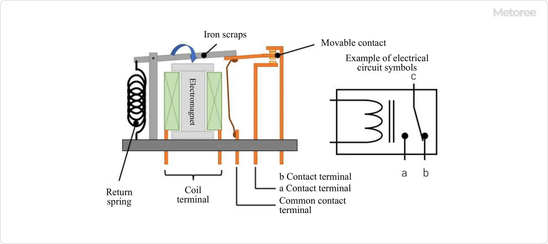
Compared to AC solenoids, DC solenoids do not generate inrush current when energized and are quieter than AC solenoids. Normally, a DC solenoid consists of the following components: a main frame, a coil, a spring, a fixed iron core, and a movable iron core.

When current flows through the coil, a magnetic field is generated at the same time, and the movable iron core is attracted to the fixed iron core by electromagnetic induction, enabling pull-type operation. While the coil is energized, the movable iron core is attracted to the fixed iron core, and when the coil is de-energized, the movable iron core returns due to spring force.

On the other hand, there is a push type that has a push bar on the fixed iron core to push out the push bar as soon as the movable iron core is attracted to the fixed iron core. By changing these tip shapes, various operations can be realized at low cost.

Other Information on DC Solenoid

1. Difference Between AC Solenoid and DC Solenoid

AC solenoids feature higher starting current and pull force than DC solenoids. However, if an AC solenoid is overloaded and locked during movement, a large current will continue to flow, resulting in coil burnout. Therefore, when adopting AC solenoids, it is important to design them with safety considerations such as thermal fuses and overcurrent protection.

On the other hand, DC Solenoid has a small current and low pull force, so even if a moving part is overloaded or locked, the coil will not be burned out, Therefore, it is necessary to select the right solenoid depending on the operating conditions. 

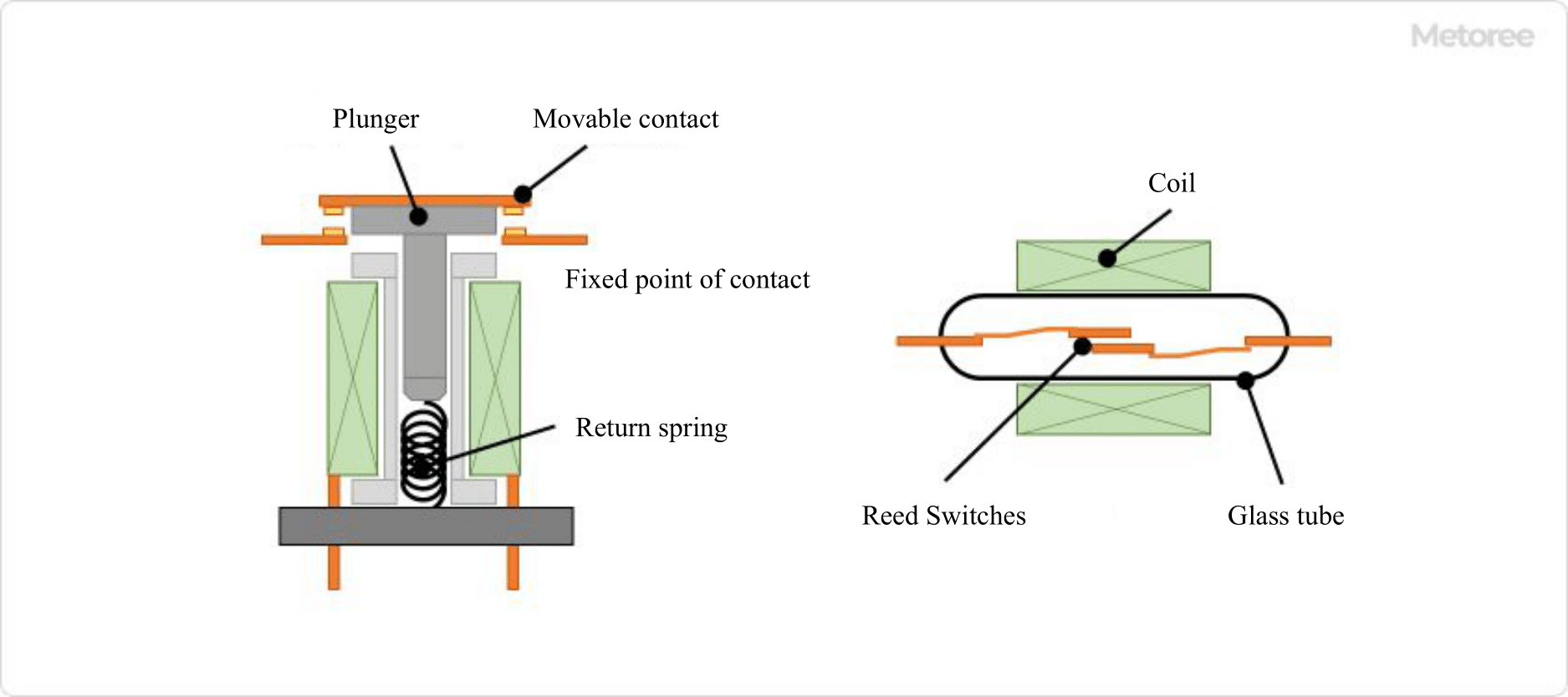
2. Self-Holding Solenoid

A self-holding solenoid is a solenoid coil with a high-performance permanent magnet that is momentarily energized. The moving part, commonly called a plunger, is attracted and then held in place by the permanent magnet.

With its short energizing time, this linear movable type solenoid is ideal for electrical equipment aiming at ultra energy saving, and is an effective component for extending the operating life of storage batteries and lowering temperature rise, for example. There are two types of solenoids: a one-directional retention type in which the moving part attracts and holds in one direction when the coil is energized, and a two-directional retention type in which the moving part tries to move and hold in two directions by making a series connection of one directional retention type and passing electricity through each coil winding section.

Self-holding solenoids have two types of pole shapes: conical type and horizontal type for one-directional solenoids, and only conical type is standard for two-directional solenoids because the stroke is fixed. Since the magnetic pole shape is used according to the size of stroke and holding force, it is important to carefully check the specifications of each solenoid’s characteristic curve in advance.

カテゴリー
category_usa

Automotive Relay

What Is Automotive Relay?

車載用リレー

Automotive Relays are relays designed to fit the control of electrical components in automobiles.

There are many Automotive Relays for different applications. Since the electrical circuit design differs according to each automobile manufacturer, various relays are manufactured and sold according to the automobile manufacturer’s standards and according to the load.

Recently, when repairing electrical components in the event of an automobile breakdown, it has become possible to quickly repair the broken Automotive Relay in the electrical circuit by replacing the entire module at once.

Applications of Automotive Relays

Automotive Relays are used as relays for electrical circuits related to the control of automobiles. Automotive Relays come in many types, including relays used to control lamps such as headlights and taillights, and motor control relays used to operate power windows and door mirrors.

They are also indispensable in the electrical circuits of automobiles, such as relays used to control air conditioners and rear-glass heaters, and those used in circuits required for battery charging.

Features of Automotive Relays

89_Automotive-Relays_車載用リレー-1.png

Figure 1. Example of a typical relay structure

Automotive Relays generally have a simple structure consisting of an electromagnet with an enameled wire coil wound around an iron core, a movable contact, and a fixed contact.

There is no special structure as a control relay, but it is designed with weight reduction, vibration resistance, and durability in mind. The weight of an automobile affects fuel efficiency and driving performance. Although each Automotive Relay is lightweight, it is important to reduce its weight since many Automotive Relays are used in a single vehicle.

Also, unlike household electrical appliances, electrical components used in automobiles are constantly exposed to vibration from running and gasoline engines. To increase the durability of automobiles, relays with excellent vibration resistance and durability are used.

Another advantage of relays is their low operating noise. Automotive Relays used for motor control, such as power window operation, are often designed to be small and quiet. Another feature of relays is that they are designed for mass production to the specification requirements of each automobile manufacturer.

Types of Automotive Relays

There are various types of Automotive Relays depending on their mechanisms.

1. Hinged Relay

The electromagnetic force generated by an electromagnet attracts a piece of iron (movable contact) and turns the contact ON/OFF by its movement. In the relay shown in Figure 1, when the electromagnet is energized, the iron strip (movable contact) is attracted to the electromagnet, turning the a-contact ON and the b-contact OFF. When the current is removed, the restoring force of the return spring causes the iron strip to return to its original position, turning the a-contact OFF and the b-contact ON.

2. Plunger Type Relay

89_Automotive-Relays_車載用リレー-2.png

Figure 2. Example of a plunger-type relay structure

When the plunger is attracted by electromagnetic force and inserted into the coil, the electromagnetic force is also generated on the plunger side, resulting in a strong attractive force. This mechanism allows the plunger to travel a large distance, making it possible to control large relay contacts.

An example of use is the EV relay (SMR) shown below. The reed relay has a contact structure with a pair of magnetic leads. A coil is wound around a glass tube, which moves the reeds to turn the contacts on and off.

89_Automotive-Relays_車載用リレー-3.png

Figure 3. EV Relay (SMR) Usage Example

Among Automotive Relays, there is a relay for EVs. This relay is called an SMR (system main relay) and is inserted into the high-voltage circuit on the way to send the high power from the vehicle’s high-voltage battery to the drive inverter and other devices to open and close the main power source.

In the event of a vehicle collision, the SMR is controlled to disconnect the high-voltage battery to prevent secondary disasters such as electric shock, etc. Relays for EVs are required to be able to interrupt high-voltage DC in a short time and be compact and lightweight.

カテゴリー
category_usa

Shock Absorber

What Is a Shock Absorber?

Shock Absorbers
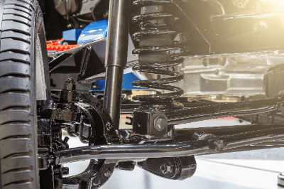
A shock absorber is a device that reduces vibrations in machinery and buildings.

In addition to suspensions, passenger cars and motorcycles use shock absorbers to reduce the impact from the ground. Springs attached to shock absorbers, absorb the shock and provide a comfortable ride.

If shock absorbers fail due to aging, it is very dangerous because their ability to absorb shock decreases, making it difficult for the brakes to work. It may also make it difficult to turn corners.

Uses of Shock Absorbers

Shock absorbers are mainly used in vehicles.

The following are examples of applications of shock absorbers:

  • Passenger vehicles such as cars and buses
  • Motorcycles, such as motorcycles and mountain bikes
  • Rail vehicles

These vehicles are equipped with shock absorbers to absorb shocks traveling on the ground. Telescopic cylinder shock absorbers are used for passenger cars, while height-adjustable shock absorbers with variable spring positions are sometimes used for motor sports vehicles with low vehicle height.

Shock absorbers called oil dampers or seismic isolation dampers are sometimes used for vibration control of houses and other structures.

Principle of Shock Absorbers

Shock absorbers can be rotary or telescopic, and telescopic shock absorbers are often used in vehicles.

In a telescopic shock absorber, the shock absorber is built inside the spring. The cylinder receives the energy of the spring, which vibrates upon impact, and absorbs the vibration by moving slowly within the hydraulic system.

At this time, the vibration energy is converted into heat energy, which causes the shock absorber to heat up. Telescopic shock absorbers can be further classified into two types: mono-tube and twin-tube.

1. Mono-Tube

Mono-tube shock absorbers are simpler in construction than twin-tube shock absorbers. A piston moves up and down inside a partially oil-filled cylinder by means of a rod that transmits the vibration of a spring. Hydraulic pressure is applied to the piston, which dampens vibration and absorbs shock.

2. Twin-Tube

The mechanism of the twin-tube is almost the same as that of the mono-tube. An additional cylinder with an oil valve is installed outside the mono-tube cylinder, making it a stronger design than the mono-tube. Twin-tube systems are installed in many passenger cars.

Regular maintenance is necessary because oil leakage due to shock absorber deterioration affects the mileage and the rate of deterioration.

How to Select Shock Absorbers

The general procedure for selecting a shock absorber is as follows:

  • Confirm the conditions of use
  • Tentatively select a shock absorber based on the conditions
  • Calculate the total energy of the collision
  • Calculate the equivalent mass
  • Evaluate the tentatively selected product

The items that must be checked when selecting a shock absorber are the maximum mass, maximum velocity, and maximum thrust of the impacted object. Care should be taken to remember to add this to the total energy, especially if thrust is generated by free fall or cylinders.

Equivalent mass is also known as the weight effect value, and each product has its own allowable range. If it exceeds the allowable range, a high reaction force will be generated at the end of the Shock Absorber’s stroke, resulting in poor shock absorption. If the equivalent mass exceeds the allowable range described in the product catalog, another Shock Absorber should be considered.

Other Information on Shock Absorbers

Shock Absorber Life Span

Shock absorber performance deteriorates with age. As the performance of a car’s shock absorber deteriorates, the tires and brake pads will wear out faster. If the car continues to be driven as it is, the shock absorber itself may break or leak oil.

The durability of a car’s suspension is generally 100,000 km or 10 years. It is also said that the recommended replacement period for shock absorber is 80,000 km. However, the lifespan depends on the roads used and the way of driving.

Highways and mountain roads place a greater load on the car and tend to deteriorate shock absorbers more easily. Unlike tires, for which there is a correlation between mileage and rpm, shock absorbers are also characterized by the fact that it is difficult to determine a definite replacement time. Therefore, it is important to determine the timing and perform regular maintenance.

カテゴリー
category_usa

Lock-in Amplifier

What Is a Lock-in Amplifier?

Lock-in Amplifiers

A lock-in amplifier is a device that has a circuit capable of extracting a component signal with a specific frequency from an input signal.

A lock-in amplifier removes noise by multiplying a reference signal and an input signal by a mixer on the device, and extracts a signal of the desired specific frequency by a low-pass filter. A device-specific value called the time constant is set, and the larger the time constant, the smaller the fluctuation of the output signal.

Uses of Lock-In Amplifiers

Lock-in amplifiers are often used in the field of optics, especially in spectroscopic measurements. They are sometimes used in combination with microscopes. Specific uses of lock-in amplifiers include astrophysical measurements such as astronomical observations, spectroscopic measurements of thin films on the order of nanometers and other experiments in which weak signals are detected.

In measurements where the sample-derived signal is weak, such as thin films less than several hundred nanometers thick, a device that amplifies the signal and eliminates noise, such as a lock-in amplifier, is indispensable. In addition, it is often used in fluorescence microscopes, Raman spectroscopy microscopes, and probe microscopes, such as atomic force microscopes.

Principle of Lock-In Amplifiers

The operating principle of lock-in amplifiers is a circuit like signal processing that detects a signal of a desired specific frequency from an input signal by amplifying the input signal with a preamplifier, multiplying it with a reference signal with a mixer, and removing excess noise components with a low-pass filter.

Within the lock-in amplifier, the input signal is multiplied by the reference signal to produce an output expressed as the sum or difference of the frequencies of the input and reference signals. If Vi=Acos(ωit+Φ) for the input signal and Vr=Bcosωrt for the reference signal, the frequency of the output is proportional to {cos[(ωi-ωr)t+Φ]+cos[(ωi+ωr)t+Φ]}.

However, since the Lock-In Amplifier acts as a low-pass filter, the only remaining component is the signal with ωi-ωr close to 0. In other words, by passing the signal through the Lock-In Amplifier, only the input signal whose frequency is close to that of the reference signal is extracted, and random components such as noise can be removed.

A sine wave is often used as the reference signal for the lock-in amplifier. A square wave is sometimes used as a reference signal to simplify the circuit and reduce cost, but in such cases, the noise rejection performance is inferior to that of a sine wave.

Other Information on Lock-In Amplifiers

1. Time Constant and Noise of Lock-In Amplifiers

A lock-in amplifier has what is called an inherent time constant. The time constant here is a value expressed as the product of the resistance of a resistor attached to the circuit and the capacitance of a capacitor. Since the magnitude of noise in the output of a lock-in amplifier is proportional to the reciprocal of the time constant, the larger the time constant, the smaller the noise in the output signal. The magnitude of a typical time constant is about 10 milliseconds to 10 seconds, while the time constant of a device that performs digital processing is about 1000 seconds.

A lock-in amplifier is affected by the signal-to-noise ratio (signal-to-noise ratio in dB), which is a measure of the noise level of the input signal. If an amplifier with a poor noise level is used in the preceding stage, the measurement accuracy of the lock-in amplifier will deteriorate, so attention should be paid to the noise level of the input signal.

2. What Is a Chopper?

A chopper is a device that rotates blades in a fixed cycle. High-sensitivity measurement combining a lock-in amplifier and a chopper is one of the most common methods in spectroscopic measurement.

By placing it on the optical path of continuous light, light is blocked when the blade is on the optical path and light is allowed to pass through when the blade is not on the optical path, thereby converting the measured light into a signal with a constant period. In measurements of crystals with large absorption coefficients or optical waveguides with large propagation loss, the measurement light is strongly absorbed by the sample, resulting in a smaller intensity of detectable light and relatively large noise effects.

In such measurements, it is more effective to use a lock-in amplifier and a chopper together. By modulating a signal with low noise and high frequency using a chopper or modulator and demodulating it efficiently using a lock-in amplifier, a signal with low noise can be obtained at the original frequency.

3. Digital Lock-In Amplifier

Today’s lock-in amplifiers are rapidly becoming digital as their frequencies are extended. A reference signal with an excellent signal-to-noise ratio and a steep low-pass filter are essential to improve the performance of a lock-in amplifier.

By utilizing a PLL (phase-locked loop) to generate a new digital sine wave internally that matches the frequency and phase of an external reference signal, distortion and extraneous noise are suppressed, and a reference signal with excellent signal-to-noise ratio is available. Steep filter characteristics can also be achieved by using a multi-stage digital low-pass filter. With the advent of this digital lock-in amplifier, high-frequency measurements up to 600 MHz can now be realized.

カテゴリー
category_usa

Detection Switches

What Is a Detection Switch?

A detection switch is a switch used to detect the position of an object and turn it on and off or switch circuits.

They operate by detecting infrared, microwave, magnetism, light, vibration, or pressure. When a switch is used to detect contact, infrared, magnetism, light, or heat, the switch is operated by the change in electrons or resistance emitted when the built-in sensing element detects light, etc. The switch is operated by the change in electrons or resistance emitted when the built-in detection element detects light, etc.

Applications of Detection Switches

Detection switches are used in stores, residences, products, production plants, and experimental equipment. When selecting a detector switch, it is necessary to consider size, detection accuracy, noise immunity, and durability.

The following are examples of detection switches in use.

  • Automatic door systems that detect the approach of a person using infrared rays and activate the system
  • Systems in factories that detect the passage of objects and sound an alarm
  • Detection systems for IC cards and magnetic strip cards at entrance gates

Principle of Detection Switches

Among detection switches, this section explains the detection methods of switches that operate by contact, switches that operate by magnetism, switches that operate by light, and switches that operate by temperature change.

  • Contact type: In the case of contact sensing, the change in pressure due to contact is measured by the amount of change in resistance of the sensing element using a diaphragm or the like, and the switch is operated. Other methods include mechanical contact actuation by contact.
  • Magnetic type: Detects the amount of change in magnetism using a sensing element such as a reed switch, Hall element, or magnetoresistive element to drive the switch. Depending on the type of sensing element used, there are switches that do not require a power supply, switches that can respond quickly, and switches with high sensitivity.
  • Optical type: Switches are operated by detecting light using a sensing element called a photodiode. A photodiode is a sensing element that converts light into electricity.
  • Thermal type: A thermal resistive element, whose resistance changes with temperature, is used as a sensing element to operate the switch. A diaphragm or the like is used to detect the amount of resistance changed by temperature.

Types of Detection Switches

There are two types of detection switches: “contact type” and “non-contact type” as the first type of detection method.

1. contact-type detection switch

Contact-type detection switches are a method that switches the contact points by the action of a physical force. Since the sensing body directly contacts the switch to switch the circuit, there is no error in detection, but there is a disadvantage that the physical contact causes the detection switch to malfunction and deteriorate over time.

2. non-contact detection switches

Non-contact detection switches are detection switches activated by magnetism or light. Unlike contact-type switches, there is no direct contact with the sensing element, so the main body of the sensing switch has a long service life. However, they tend to be more expensive than simple contact-type detection switches.

カテゴリー
category_usa

Spindle Motors

What Is a Spindle Motor?

Spindle Motors
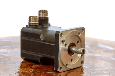
A spindle motor is a motor in which the motor part of the power source and the rotating part are integrated.

Since there is only one rotating shaft, the equipment configuration is simplified. A spindle is the rotating shaft of a rotating machine.

It is also called a spindle unit, a term used for machine tools such as lathes. Therefore, a spindle motor refers to a motor integrated with a spindle.

A typical rotation control device consisting of a motor, gears, and belts tends to be complicated to control due to the large number of parts. Spindle motors, however, make it easy to add multiple rotating shafts in parallel in a space-saving manner.

Uses of Spindle Motors

Spindle motors are widely used inside processing machines. The following are examples of spindle motor applications.

A wide range of product lineup exists, from high-torque types to products capable of high-speed rotation. It is possible to select the optimum product from a variety of spindle motors according to the application.

In recent years, spindle motors have also been used in articulated robots, where the axis of rotation of the robot arm is matched with the axis of the spindle motor. Taking advantage of their space-saving characteristics, spindle motors can also be used to drive HDD rotation.

Principle of Spindle Motors

The structure of spindle motors is often very similar to the widely used servo motors. The spindle is installed coaxially with the axis of rotation. There are two types of motors used: synchronous motors and induction motors.

1. Synchronous Motor

Synchronous motors consist of a rotor made of permanent magnets fixed to a rotating shaft and multiple circular stator units installed around the periphery of the rotor. The stator consists of electric wires wound around an iron core, and when an alternating current flows through it, it acts as an electromagnet and temporarily restrains itself.

Because the phase of the AC current changes from moment to moment, the polarity of the electromagnets also changes with time. Since the polarity of the rotor’s permanent magnet is fixed, it can rotate the rotor by alternating attraction and repulsion with the stator.

2. Induction Motor

Induction motors are motors that use a conductor rotor instead of the permanent magnet rotor of synchronous motors. A cage-shaped metal part is often used for the conductor rotor.

The principle is that a rotating magnetic field generated by the stator generates an electric current in the rotor conductor, causing electromagnetic induction action that rotates the shaft. Unlike synchronous motors, this type of motor is not suitable for fine positioning because of an error called “slippage” in the rotation phase. However, they are widely used for high output products because of their low cost and small number of parts.

Other Information on Spindle Motors

Differences Between Spindle Motors and Servo Motors

Spindle refers to the rotary shaft of industrial rotating equipment used for cutting and grinding. Therefore, the main purpose of spindle motors is cutting and grinding. Motors with ultra-high speed rotation and high torque are often used.

In contrast, servo motors are widely used in precision machinery that requires strict positioning accuracy. Assembly robots and automatic packaging equipment are examples. Driving devices such as encoders are used in motors to detect the rotational position and speed of the rotor.

This detection information is communicated with a PLC or driver to implement feedback control, enabling high-speed rotation to be controlled with high precision. Both spindle motors and servo motors of all types can be applied.

However, induction motors are often used for spindle motors and large-capacity servo motors, while synchronous motors are often used for small-capacity servo motors.

カテゴリー
category_usa

PCB Design

What Is PCB Design?

PCB design is the design of a Printed Circuit Board (PCB).

A printed circuit board is a so-called patterned circuit board in which copper is applied to a PCB board made of materials such as glass, fiber, or paper phenol, and then etched using a solvent known as etching, leaving only the copper foil for the circuit portions.

In other words, PCB design is the detailed design of patterns and layer configurations on PCB boards, along with chip components such as ICs and LCRs to be placed, using dedicated circuit diagrams, simulators, wiring layouts, and CAD tools for electromagnetic field, heat generation, and stress analysis.

Uses of PCB Designs

The ultimate purpose of PCB designs is to be used in practical applications in the form of PCBs, which are used inside electrical appliances such as air conditioners, refrigerators, and televisions. The tools used to materialize the PCB as an electronic circuit board to be built into the product are dedicated schematic CAD and board pattern design CAD.

The PCB design procedure generally consists of designing an electronic circuit, converting the circuit into an actual parts list, and then creating a copper foil pattern circuit on the board in the form of a pattern that represents the circuit and mounted parts.

Principles of PCB Designs

To explain the principle of PCB designs, it is necessary to understand it from the principle of PCB, which, as mentioned above, refers to printed circuit boards, which are made of insulators such as glass, fiber, or paper that do not conduct electricity. The PCB is the result of etching the copper foil except for the areas that are to be electrically conductive.

The pattern design information necessary to form the pattern circuit on the PCB is the PCB design itself, which is the embodiment of how the circuit will be realized on the PCB. The pattern design information is the electronic circuit to realize the necessary functions of the product at the first stage, as described in the usage of the product as the main source of information.

Without this circuit diagram, nothing can begin. After the circuit diagram and mounted components such as ICs and chip components are created and registered in CAD, the circuit diagram information is then dropped into a dedicated board pattern design CAD system. This work is usually handled by staff dedicated to pattern design or by an outsourcing company.

The circuit designer is in charge of inputting the necessary information, and the minimum information required at that time is the board dimensions, hole diameters, board, and copper foil thicknesses, and the placement of mounted components, which must be specified in advance. 

カテゴリー
category_usa

Spectrum Analyzers

What is a Spectrum Analyzer?

A spectrum analyzer is a type of electrical measuring instrument.

The spectrum analyzer screen displays frequency on the horizontal axis and amplitude on the vertical axis, representing frequency as a component.

There are two types, one for high-frequency and the other for low-frequency, and each has different applications. The high-frequency version is mainly used to “display the distribution of frequency components” and “analyze the components of AC power” of the high-frequency signals of radio waves. In contrast, the low-frequency version is used for “noise analysis” and the like.

Since inaccurate results may be caused by static electricity, excessive power signals, etc., we recommend carefully checking the usage and conditions before use.

Uses of Spectrum Analyzers

High-frequency spectrum analyzers are used for inspection, measurement, design, repair, transmission wave, and the spurious measurement of radio equipment, transmitter, and receiver. Various setting items are important, so appropriate values must be entered according to the application.

For low-frequency applications, some products are small and portable and are widely used in field tests for field strength measurement, frequency identification, noise measurement, machine diagnosis, structural analysis, and vibration testing. in wireless run installation work.

Spectrum analyzers are sometimes compared and described with oscilloscopes. Typically, oscilloscopes are used with spectrum analyzers, which can capture and observe signals in terms of frequency, since they are often used to observe the time axis in the lower frequency range. oscilloscopes and spectrum analyzers observe signals from different angles and have different areas of expertise, so the necessary information should be considered before use.

Principle of Spectrum Analyzers

Heterodyne describes a signal processing technique and refers to the signal frequency created by converting the difference in frequencies generated by mixing or combining other frequencies with the received radio wave.

Superheterodyne generally refers to a reception method that converts the received signal into a fixed intermediate frequency (IF) that is easier to process than the original carrier wave. method are sometimes collectively referred to as superheterodyne.

In the superheterodyne-tuned sweep method, the input signal is passed through an attenuator and a low-pass filter while being limited by them. sweeps and measures the band-limited frequency with the frequency resolution set by the band-pass filter.

The FFT method has become popular in recent years due to its development. It is the same as the superheterodyne tuned sweep method up to the point where the input signal is frequency converted. In some cases, the output of the bandpass filter is converted to a digital signal by an AD converter and then the frequency is displayed by a fast Fourier transform. Since the time to measurement can be shortened, this method is suitable for measurement when the spectrum changes quickly.

カテゴリー
category_usa

Microswitches

What Is a Microwave Switch?

Microwave Switches

Microwave Switches are components that detect the position of an object and provide a contact output. They are mainly used as switches for detection, but may also be used for operation.

The contact output of Microwave Switch is incorporated into a control circuit to operate or stop a machine. Microwave Switch contacts themselves generally have an allowable current of about several amperes. The part that comes in contact with an object has an actuator, which can be a button, roller, or lever type.

Uses of Microwave Switch

Microwave Switches have a snap-action mechanism and are characterized by their high accuracy in detecting position.

They are used in door interlocks, safety switches for vending machines, microwave ovens, elevators, and industrial equipment. They are also used in sensors that detect the opening and closing of printers and other equipment.

Sizes are classified into four types, from general type to ultra-miniature, and are available in reverse action type for locations subject to severe vibration or shock, magnetic quenching type for applications requiring stable operation of DC circuits, and immersion-proof type for high sealing performance. They have a wide range of applications from industrial equipment to home appliances.

Principle of Microwave Switch

Microwave Switch is divided into five parts, and the movement of the actuator leads up to the contact point.

1. Actuator Part

External force or motion is transmitted to the internal mechanism. The actuator is connected to the snap-action mechanism, which can be a button, roller, or lever type.

2. Snap Action Mechanism

It consists of parts such as a spring, a movable piece, a common terminal, and a receiver. When the force applied from the actuator increases, the movable piece and spring move the contacts.

3. Contact Point

There are two types of contacts: normally open and normally closed. Generally, each Microwave Switch has one of these contacts, but some have only one. There are crossbar type and rivet type contacts, and they are used according to the voltage and current of the circuit. Gold, silver, or plating is used as the material.

4. Terminal

Terminals connect the switch to the circuit. Terminals are available in soldering, connector, screw-tightening, and printed circuit board types, and the connection method is selected according to the application.

5. Case

The case protects the circuit and mechanism, and the resin is selected according to the required mechanical strength and heat resistance.

Uses of Microwave Switch

1. Doors and Printer Open/Close Covers

Microwave Switches are used to detect the position of doors and covers. Microwave Switches with actuators that have a wide range of shapes are used. Microwave Switch can be installed in a limited space.

2. Detecting the Opening and Closing of Dishwasher Covers and Washing Machine Lids

Microwave Switches are used to detect the position of covers and lids. These devices may be exposed to water, so Microwave Switches are waterproofed.

3. Mouse Operation Input

This is used in a mouse not as a position detection switch but as an operation switch. Microwave Switch detects mouse clicks and outputs them to the computer.

Other Information on Microwave Switch

1. The Difference Between Microwave Switch and Limit Switch

Microwave Switches and Limit Switches are often confused with each other. Limit switches, like Microwave Switches, are used as detection switches, but there are differences in construction and application. Limit switches consist of a built-in Microwave Switch in a plastic or metal case.

Limit switches are used to improve weather resistance when exposed to rainwater. Limit switches are also used in some industrial facilities as a measure against dust and oil.

2. Snap-Action Mechanism of Microwave Switch

A snap-action mechanism is a mechanism that quickly switches the movable contacts regardless of the speed at which the switch is operated. In contrast, a mechanism in which the operating speed is the moving speed of the movable contacts is called a slow-action mechanism.

Microwave Switches with snap-action mechanisms are characterized by a fast switching speed of the contacts, which minimizes arcing between the contacts. Even small Microwave Switches can have long contact life and excellent durability.

カテゴリー
category_usa

Electrostatic Instrument

What Is an Electrostatic Instrument?

An Electrostatic Instrument is device that measures the voltage of static electricity generated on the surface of an object.

This instrument is equipped with a surface potential sensor that enables non-contact measurement when pointed at the object being measured. Electrostatic Instruments are also called Surface Potentiometers or Electrostatic Potential Meters, and are mainly used in production processes in the manufacturing industry.

Uses of Electrostatic Instruments

Electrostatic Instruments play a crucial role in addressing issues caused by static electricity during the production process. Accurate measurement of static electricity is the first step in implementing preventive measures and evaluating their effectiveness. Depending on the process, these instruments may also be used for continuous monitoring of static electricity generation.

1. Foreign Matter Adhesion

Trouble occurs when charged foreign matter, such as dust, adheres to a charged product. For example, in the painting process, this can cause unevenness in the coating. 

2. Electrostatic Destruction (ESD Destruction)

Semiconductor components such as integrated circuits can be destroyed by electrostatic discharge.

3.Malfunction

Devices that operate with small currents and voltages, like electronic balances, weight checkers, and metal detectors, may be affected by electromagnetic noise when static electricity is discharged. 

4.Discharge to the Human Body

Electrostatic discharge from a charged object to the human body not only causes pain and discomfort to the human body, but can also cause equipment malfunction and ignition of combustible materials.

Principle of Electrostatic Instrument

When the surface of an object is charged and static electricity is generated, an electric field is generated around the object. Electrostatic Instruments measure the strength of this electric field and calculate the electrostatic voltage. The principle of a typical Electrostatic Instrument, such as Surface Potentiometer, is as follows:

The surface potential sensor uses the electrostatic induction phenomenon. When the sensing electrode receives an electrostatic field intensity Eo (proportional to the charging voltage Vo) from a charged object, an induced charge q is accumulated on the surface of the sensing electrode. When a shield plate of a size that covers the entire detection electrode is placed between the detection electrode and the object and rotated at a constant speed, the induced charge q accumulated on the detection electrode is discharged at the moment the shield plate covers it, and when the shield plate passes by, the induced charge q is accumulated again. This periodic movement of charge q, that is, the magnitude of the alternating current Is, depends on the electric field strength, so the charging voltage Vo of the object surface can be obtained by measuring the current Is.

However, in the this measurement method, the measured value depends greatly on the distance between the surface potential sensor and the object to be measured. The further away the object is from the sensor, the weaker the electric field becomes, so it is inevitable that the measured value will appear smaller. Therefore, it is necessary to keep the distance between the surface potential sensor and the object to be measured at the specified distance.

To address this distance-dependent measurement issue, another device is the voltage feedback-type surface potential meter. In this system, a high-voltage power supply is connected to the sensing electrode, and the voltage output of the high-voltage power supply is adjusted so that the alternating current Is becomes zero. Since the current Is stops flowing when the voltage of the object to be measured and the voltage of the sensor are the same, the output voltage of the high-voltage power supply at that time can be said to be equal to the charged voltage of the object to be measured.

How to Use Electrostatic Instruments

To measure the electrostatic charge of a charged object with a typical Electrostatic Instrument, the procedure is as follows:

1. Place the surface potential sensor at the distance specified by Electrostatic Instrument, with the detection electrode of the surface potential sensor parallel to the surface to be measured.

2. Set the measuring range higher than the expected voltage and start measurement. When a rough measurement value is obtained, adjust the measuring range and adopt the measured value.

When measuring with a voltage feedback type surface potential meter, the detection electrode of the surface potential sensor is placed parallel to the surface of the object to be measured, but the distance from the object does not need to be strictly defined. The voltage of the high-voltage power supply is gradually increased to find the point where the alternating current flowing to the detection electrode becomes zero. The output voltage of the high-voltage power supply at that point becomes the charged voltage of the object to be measured, and the unit of measurement value is V or KV. It is important to select an appropriate instrument based on the assumption of the maximum static electricity voltage.

Other Information on Electrostatic Instruments

Causes and Prevention of Static Electricity

The following mechanisms are known to generate static electricity:

1. Peeling Charge

This occurs when overlapping materials are peeled off, such as when a protective film is pulled off a plastic sheet.

2. Friction Charging

Occurs when objects rub against each other, such as when mixing things, taking off clothes, or when motors rotate.

3. Other Charging

Electrostatic Instrument is used to measure the electrostatic charge of objects exposed to such conditions, such as grinding and powder charging. In particular, semiconductor components are highly likely to fail due to Electrostatic Instrument discharge, so it is necessary to check the inside of the process with Electrostatic Instrument on a regular basis.

The following are specific examples of measurement targets in the production process:

  1. Trays containing semiconductors, other electronic components, and their parts, their protective films, and storage shelves.
  2. Work clothes, work shoes, work process desks, chairs, and floor surfaces.
  3. Grounding bands and grounding attachments.
  4. Manufacturing equipment, such as production equipment, inspection equipment, jigs and tools, soldering irons, etc.
  5. Work standards and their protective plastic cases.
  6. Display parts of monitors.
  7. Various types of purchased films.

When the generation of static electricity is unavoidable, ionizers and other static eliminators are installed to actively eliminate static electricity, but measurement using Electrostatic Instruments is essential to ensure the effectiveness of such measures.