カテゴリー
category_usa

Theodolites

What Is Theodolite?

Theodolites

Theodolite is a surveying instrument that precisely measures horizontal and elevation angles.

By rotating the telescope mounted on a precision rotation and precision vertical swing stage independently in the horizontal and vertical directions, it is possible to accurately measure and determine angles between distant measurement points.

It is an indispensable instrument for surveying in the civil engineering and construction fields and is always used in conjunction with a tripod.

Currently, there are three main types of theodolites: optical theodolites, digital theodolites, and laser theodolites.

Application of Theodolite

Theodolites are used for surveying at civil engineering and construction sites.

The accurate measurement of horizontal and elevation angles makes them particularly suitable for the following applications:

  •  Right angle (90°) measurement on the target ground
  •  Setting up a precise horizontal straight-line path
  •  Precise measurement of elevation and tilt angles

Theodolite is mounted on a special tripod to keep it horizontal and completely fixed on the reference point during surveying.

Combined with precise distance measurements, it is also possible to locate any single point in any space.

Theodolite Principle

A theodolite is essentially a telescope mounted on a precision rotation stage in the horizontal plane and a precision swing stage in the vertical plane.

This allows the telescope to rotate independently horizontally and vertically to precisely determine the angle between any two measurement points.

Almost all theodolites have a telescope magnification of 30x.

They must be mounted on a tripod to secure their position during surveying and have a screw mount at the bottom.

Currently, there are three types of theodolites: those that combine an ordinary optical telescope with a digital micrometer (optical theodolite). Then ones that have a mechanism that displays the surveyed value in the field of view by looking through the telescope at the target point (digital theodolite), and the other is a laser theodolite that combines a digital theodolite and a visible laser to create a clear surveying reference line.

When used in conjunction with a distance surveyor, it is possible to determine the position of any arbitrary point in space.

Types of Theodolites

There are three types of theodolites: optical theodolites, digital theodolites, and laser theodolites.

Optical theodolites use an optical micrometer built into an optical telescope to read angles, and since they do not use batteries, there is no need to worry about running out of power.

Digital (electronic) theodolites measure and display angles electronically. It is the most mainstream of the three types of theodolites, characterized by fast readings and low reading errors.

The laser type incorporates a laser diode and features a laser spot that illuminates the observation point. It is effective in underground and tunnel construction.

Differences between Theodolite, Transit, and Total Station

Theodolite and Transit are both surveying instruments that measure two types of angles: horizontal and elevation angles. The one that reads angles on a scale is called a transit, while the one that displays angles digitally is called an electronic theodolite. Electronic theodolites are the most common type of theodolite.

In contrast, a total station can measure both distance and angle with a single unit. A total station is a theodolite with an additional function to measure distance. A total station is also called a lightwave because it has the function of a lightwave rangefinder. They are more expensive than theodolites because they have more functions, such as a microcomputer and operating system that can be remotely operated.

While total stations can measure both distance and angle, the accuracy of angle measurement is generally higher with theodolites. Therefore, they are used on relatively small civil engineering sites.

Differences in angle detection methods of Theodolites

There are two types of surveying instruments such as theodolites: those that require the telescope to be rotated after turning on the power to survey, and those that can survey immediately after turning on the power. This is due to the difference between the two methods: incremental and absolute.

The incremental method measures the amount of angle change by adding the number of slits engraved on the protractor. One of the slits has a marker for the zero point of the angle, which is 0 degrees for horizontal angles and 90 degrees for vertical angles. The angle cannot be measured unless it passes through this zero point after the power is turned on.

The absolute method measures the current angle by reading the pattern written on the protractor, so the angle can be read immediately after turning on the power. However, it tends to be more expensive than the incremental method.

How to Use Theodolite

Centering and leveling are performed during the installation of the theodolite, but first, the flat and circular bubble tubes and centering telescope must be inspected and adjusted to ensure that these are performed correctly.

After the theodolite inspection and adjustment are completed, the theodolite is installed. There are several precautions to be taken when using the theodolite. Theodolite is a precision instrument and should not be subjected to vibration or shock. When transporting it, it should not be carried on the shoulder while attached to the tripod. If the camera gets wet in the rain, dry it well. If the lens gets dirty, wipe it gently with a soft cloth moistened with alcohol. Also, remove the batteries when not in use for long periods. Tighten the tripod securely on the centering cans and thumbscrews. When transporting the tripod, make sure the thumbscrews are tightened securely and do not point the base of the tripod at people.

To set up the theodolite, first set up the tripod and perform “centering” to align the center of the theodolite body and the measurement point on the same vertical line. Next, the vertical axis of the theodolite is adjusted to the vertical plane, and the center of the telescope is aligned with the center of the prism. These steps are repeated and adjusted to ensure that everything is aligned so that measurements can be taken.

After installation, positive and negative observations are made to eliminate mechanical errors. Then, inspect and adjust the flat-plate bubble tube, the circular bubble tube, and the centripetal telescope to ensure that the measurements are normal.

Cautions for using theodolite

There are several precautions to be taken when using a theodolite. Theodolites are precision instruments and should not be subjected to vibration or shock, and should not be carried on the shoulder while attached to a tripod. If the camera gets wet in the rain, dry it well. If the lens gets dirty, wipe it gently with a soft cloth moistened with alcohol. Also, remove the batteries when not in use for long periods. Tighten the tripod securely on the centering cans and thumbscrews. When transporting the tripod, make sure the thumbscrews are tightened securely and do not point the base of the tripod at people.

In addition to the theodolite itself, the choice of tripod is also important. First, there are two types of materials: wooden and aluminum. Wooden tripods are less prone to expansion due to temperature, which allows for more accurate surveying, but their high price and weight are disadvantages. In contrast, aluminum tripods are lightweight, inexpensive, and easy to carry, but they are less accurate than wooden tripods due to thermal expansion.
カテゴリー
category_usa

Thrust Bearings

What Is a Thrust Bearing?

Thrust Bearings

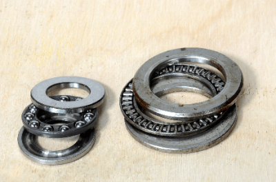
A thrust bearing is a bearing used to support loads in the axial direction (parallel to the shaft center). Thrust bearings generally do not support radial loads and are not suitable for use in high-speed rotating applications.

A bearing is a mechanical part to support a rotating body, such as a shaft, accurately and smoothly. When a shaft is rotated, the shaft is in contact with the supporting structure or support. This invariably generates resistance force and frictional heat due to friction, resulting in the loss of rotational energy. Bearings are used to prevent energy loss and heat generation due to friction.

The following standards related to thrust bearings and thrust bearings are interchangeable among manufacturers in terms of dimensions, etc.

Applications of Thrust Bearings

Thrust bearings are available in the following types, each of which has different applications.

1. Thrust Ball Bearings

Used in machine tool spindles, etc.

  • Single type: A single bearing consists of a shaft raceway, housing raceway, rolling elements (balls), and cage.
  • Duplex: A bearing consisting of a shaft raceway, housing raceway, rolling elements (balls), and cage in two pairs. Duplex bearings can accommodate axial loads in both directions.

To allow for mounting error, the housing raceway, whether single or double type, is available in spherical alignment type or with alignment washers.

2. Thrust Roller Bearings

Single, double, and triple rows are available to accommodate large loads, and the duplex type is used in the roll necks of rolling mills in steel production facilities.

  • Thrust roller bearings (thrust cylindrical and tapered roller bearings)
  • Spherical thrust roller bearings (spherical thrust roller bearings)
  • Thrust needle bearings
  • Thrust roller bearings

3. Thrust Metal Washers

Principle of Thrust Bearings

A thrust bearing consists of a housing raceway, shaft raceway, rolling elements (balls and rollers), and cage.

The shaft and shaft raceway support the axial load via balls or rollers, and the housing raceway supports the thrust load applied in a direction parallel to the shaft center axis. However, radial loads can also be supported by using thrust angular contact ball bearings.

Thrust roller bearings can also support large axial loads, while thrust needle bearings are used for smaller loads. Thrust spherical roller bearings can support large axial loads due to the spherical contact surface of the rolling elements on the housing raceway. This is also due to the degree of freedom in positioning the tapered rollers in relation to the rolling elements, which allows them to be aligned.

Lubrication of the bearing is very important when using thrust bearings. Especially for thrust spherical roller bearings, which have a complicated shape and it is difficult to distribute lubricant to all parts of the bearing.

Assembling Thrust Bearings

Thrust bearings must be assembled in the correct orientation because the assembly direction is fixed. It is especially important to determine the difference in size between the shaft raceway and housing raceway, with the shaft raceway having a smaller inner diameter. The raceway must be assembled in the correct orientation and the correct order.

When assembling, thoroughly clean each part of the raceway and apply grease to the balls or rollers. (This is not necessary in the case of oil lubrication.)

カテゴリー
category_usa

Spot Welding

What Is Spot Welding?

Spot WeldingSpot Welding is a type of welding method along with Arc Welding and Gas Welding.

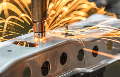
Two pieces of welded material are sandwiched between electrodes under pressure, and a large current is applied. Then, the metals are joined together by melting and solidifying in a spot manner due to electric resistance heat.

There are three basic types of welding methods: pressure welding, brazing, and fusion welding.

Spot Welding is categorized as pressure welding. Unlike arc welding, which forms a wide bead (welding surface), spot welding joins only one small point, resulting in a clean finish.

Spot Welding is also called Resistance Spot Welding because the base metal is heated by electrical resistance.

Uses of Spot Welding

Spot Welding is used to join parts of automobiles, railroad cars, and household appliances because of its ability to maintain a clean appearance.

One of the advantages of Spot Welding is that, unlike other welding methods, it welds directly across the base metal and does not require any fusing materials such as shielding gas or flux.

Another advantage of Spot Welding is that even novice welders can easily perform spot welding, whereas arc welding and gas welding are dependent on the skill of the welder. Spot Welding can be combined with a robot arm to automate the welding process.

Principle of Spot Welding

There are three types of Spot Welding: Resistance Spot Welding, Laser Spot Welding, and Seam Welding.

1. Resistance Spot Welding

Resistance Spot Welding is a method of joining two pieces of metal to be welded by applying electrode rods to them from above and below, applying pressure, and passing a large current through them to cause the base metal to melt and solidify with the heat generated.

When the term Spot Welding is used, it simply means resistance spot welding.

Electrode rods are often water-cooled. It is used to join relatively thin materials and is frequently used in the production of automobile bodies. Welding quality is determined by welding current, as well as energization time, pressing pressure, and material. These conditions must be controlled to improve the quality of the nugget, which is the joint in Spot Welding.

In Resistance Spot Welding, the temperature near the weld zone is lower than that of arc welding, so the effect of heat is limited to a narrow area. Therefore, it is characterized by less deformation and residual stress after welding. On the other hand, because it heats with the heat of high-current electric resistance, the capacity of the welding machine is larger than that of arc welding, which has the disadvantage of higher equipment costs.

2. Laser Spot Welding

Laser Spot Welding is a method of heating base metal by irradiating it with a laser. Heating is done on one side only, and it is mainly used for welding small, thin objects or objects that require high precision.

Compared to Resistance Spot Welding, the heating time is very short for high power. This has the advantage of minimizing weld distortion.

3. Seam Welding

This is a method of continuously overlapping resistance Spot Welding. It is a type of Spot Welding. The electrode is made in the shape of a roller, sandwiched between two base materials, and heated by rotating the electrode while applying pressure and intermittently passing an electric current. It is used when watertight or airtight is required.

Other Information on Spot Welding

1. Spot Welding in Automobile Production

There are approximately 6,000 welding spots on a single automobile. The welds are made on the body, frame, suspension members, lower arms, etc.

There are many types of welding methods used in automobiles, including resistance welding, arc welding, and laser welding. Nowadays, laser welding is becoming the mainstream in terms of productivity and manufacturing cost.

Among these, Spot Welding is used to weld plate materials such as bodies and pressed doors. Spot Welding used here includes resistance spot welding and laser spot welding. 

2. Causes of Spot Welding Failures

Spot Welding uses the electrical resistance properties of metal to perform welding. And there are several causes of defects in resistance welding such as Spot Welding.

  • Insufficient joining of plates and other materials resulting from small nugget diameter
    Insufficient current flowing from the electrode to the plate or other material due to the tip of the electrode not having the proper diameter.
  • Insufficient melting or excessive indentation of the joint area of plates, etc.
    Caused by the electrode not being symmetrical when it contacts the plate, excessive current flow, excessive pressure, etc.
カテゴリー
category_usa

Spring Pins

What Is a Spring Pin?

A spring pin is a hollow pin made by bending a thin plate into a cylindrical shape and applying a mortise (slit process) to it to form a C-shaped cross-section.

Because it is hollow, it is lighter than a solid pin. It is inserted into a hole, with a hole diameter slightly smaller than the pin’s outer diameter, and used to fix or constrain rotation by spring force as the pin expands outward.

Generally, it is also used synonymously with a rolling pin, tension pin, etc.

Use of Spring Pins

Spring pins are used for locating, preventing rotation, and retaining parts. Since the spring force of the pin acts to secure the part, high hole diameter accuracy is not required. The pin can be adequately secured in drilled holes without reaming. Therefore, it is easier to use than solid parallel pins or tapered pins. The spring force also makes them less likely to drop out against vibration.

There are two main types of springs, one for general use (straight) and the other for light-load use (corrugated), which are used according to their respective characteristics.

The general-use springs are used for simple fastening and positioning. Slits are available in straight and corrugated types, and both ends are tapered or R-processed to facilitate insertion into holes.

The light-load type is a simpler type of fastening that requires less load to insert than the general type. This is used for lightweight materials such as aluminum and resin that do not require high strength. Slits are corrugated and less prone to tangling, making them suitable for automatic insertion.

Spring Pin Types

Refer to the figure below for an example of spring pin use (fastening of shaft and pinion gear to prevent rotation).

Cable gland, refer to the following for an example of spring pin selection.

  • Pin O.D.: Select a pin based on the combination of the pin diameter and hole diameter listed in the dimension tables of the respective manufacturer.
  • Pin strength: Confirm that the pin meets the shear load specified in each manufacturer’s dimensional table.

Principle of spring pins

The main feature of spring pins is that they can be inserted into a machined hole with a hole diameter slightly smaller than the pin’s outer diameter. They can be fixed or rotationally restrained by the spring force that causes the pin to spread outward. Therefore, high-precision hole diameters are not required, and finishing processes such as reaming can be omitted. The pins can then be used as drilled holes, resulting in fewer processes and lower manufacturing costs.

However, they have lower shear strength than solid parallel pins and tapered pins and are not suitable for high load and high precision fasteners. If more strength is required, two pins with different outer diameters can be used in combination.

Care should be taken when using this method because the pin can easily come loose if vibrations occur in a direction parallel to the pin’s axial direction. Also, if the fastener is repeatedly rotated, the pin will easily come loose, so care is required.

To insert a spring pin, lightly tap the end face of the pin with a hammer or the like. If the spring pin is difficult to insert, slightly increase the hole diameter for fine adjustment. To pull out the spring pin, place a pin punch or similar tool on the end of the pin, tap it lightly with a hammer, etc., and pull it out.

カテゴリー
category_usa

Spiral Ducts

What Is a Spiral Duct?

Spiral-Ducts

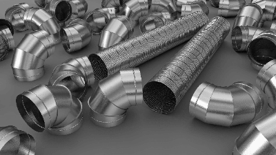
Spiral ducts are inexpensive ducts made by spiraling metal strips, taking advantage of the flexible nature of thin metal. Because spiral ducts are thin and lightweight, they are the most common type of duct used in various parts of buildings and factories.

Other types of ducts include bellows-type flexible ducts and ducts made of plastic such as polyvinyl chloride. Spiral ducts are used for air ducts unless there are special circumstances, as they are lighter and more affordable.

Uses of Spiral Ducts

When cold or warm air is sent to a room for air conditioning, it is sent through spiral ducts. They are also used in air ducts for dust collection and smoke removal. They are often found in the ceilings and walls of buildings and factories.

Zinc steel plates are commonly used for general air conditioning, but spiral ducts made of stainless-steel plates are used where corrosion resistance, weather resistance, and even heat resistance are required.

There are also spiral ducts made of vinyl chloride coated on both sides of a steel plate, which are used in acidic atmospheres and other locations where metal is not resistant to corrosion.

Principle of Spiral Duct

Spiral ducts are made of spiral-rolled metal sheets, with the two ends stacked in a haze-fold formation. The structure of the spiral duct has a reinforcing effect, so even a duct with a thin wall thickness has high strength.

Structure of Spiral Duct

Spiral ducts are made by rounding metal plates to obtain a high degree of roundness and a smooth interior, which reduces the friction of air passing through the duct and allows for efficient airflow.

Straight pipes of spiral ducts can be connected to each other by using fittings and can also be branched in multiple directions by using branches. Spiral ducts of different diameters can also be connected by using special fittings, which can be used to control the air-blowing pressure. Of course, the airflow can also be controlled by installing a regulator.

There are two types of connection methods: plug-in type and flange type. The plug-in type is connected with a plug-in joint, fixed with screws, and sealed with aluminum tape, etc. The flange type can be installed directly on-site. This allows for direct installation on-site and easy fixation and angle adjustment. On the other hand, the flange method provides a stable connection and reproducibility even after connection and disconnection are made. For this reason, the flange method is suitable for high-pressure applications or where components need to be replaced frequently.

Spiral ducts are thin metal plates with high strength, are lightweight, and can be easily fixed to ceilings. Therefore, spiral ducts can be shaped flexibly according to the shape of the building, which speeds up the construction period.

Because of this low cost and ease of use, spiral ducts are used in a variety of locations.

カテゴリー
category_usa

Strainers

What Is a Strainer?

StrainersA Strainer is a component that removes fine particles from a liquid or gas. A similar component is a line filter, but it has a different application.
Strainers are inserted upstream of equipment to protect the equipment, whereas line filters are installed to filter and normalize the fluid.

Uses of Strainers

Strainers are used in consumer products, such as automobiles. They are installed upstream of the engine in engine oil lines to provide engine protection. Other applications include sewer piping.

For industrial applications, they are often used in plants and hydraulic units. They are installed upstream of equipment such as pressure reducing valves and pumps, mainly to prevent the entrapment of foreign matter.

There are also two types of strainers: products for periodic cleaning of internal screens and temporary strainers.

Temporary strainers are disposable strainers. They are basically removed after the piping work is completed. They are available in cone and plug-in types.

Principle of Strainer

A strainer consists of a body, an O-ring, and a screen. The screen is contained in the body and is connected to the piping with an O-ring to prevent leakage. The most important part is the screen, which is made of perforated metal or mesh in the shape of a mesh.

The size of the foreign matter to be removed is determined by selecting the mesh coarseness. If the foreign material is large, the screen mesh should be coarser; if it is small, the screen mesh should be finer. There are also Y-type and U-type strainers. Basically, the Y type is used for small flow rates and the U type for large flow rates.

The pressure loss of the strainer should be noted. Installing a Strainer causes a pressure loss, and if a fine-meshed strainer is installed at the inlet of the pump, cavitation may occur.

Other Information on Strainers

1. Cleaning the Strainer

Since the Strainer uses a filter to remove debris from the fluid, debris accumulates inside. If not cleaned regularly, the filter will become clogged, resulting in various problems. The most common cleaning method is to remove the internal filter and flush it with water.

The cleaning operation is carried out by cutting off the edges at the inlet and outlet valves of the Strainer. If the line cannot be easily shut down, provide a bypass line to the Strainer in advance for cleaning. Strainer clogging is detected by monitoring the discharge pressure of the pump in the line.

It is also important to inspect the Strainer before operation, as foreign matter in the line may flow into the Strainer after a long shutdown.

2. Mesh of Strainer

In Strainers, filter roughness is generally expressed in terms of mesh. Mesh is the number of meshes in one inch. If there are 10 meshes in an inch, it means 10 meshes. In reality, there are 10 meshes in each 1″ x 1″ square, so there are 100 meshes in a 1″ square.

Strainers with double-layered filters are also available. In a dual structure filter, a coarse filter is installed on the outside and a fine filter is installed on the inside. Strainer coarseness and construction are selected based on discussions with the manufacturer and past performance.

カテゴリー
category_usa

Stud Bolts

What Is a Stud Bolt?

Stud Bolts

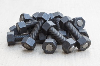
A stud bolt is a bolt that has no head like a hexagonal bolt but only a shaft with threads (male threads) on both ends. The terms “planted bolt” and “inch-cut bolt” are also commonly used as synonyms.

The threaded part at one end is screwed (implanted) into the female thread of a machine or part, and the object to be fixed is attached and fastened with a nut.

The features of stud bolts are shown below.

  • Excellent axial tensile strength
  • It can be repeatedly installed and removed.
  • Longer lengths can be easily utilized due to the absence of bolt heads.

Application of Stud Bolts

Stud bolts are used in various situations, such as assembling machine bodies and parts and fixing parts together.

A common example of assembly and fastening of machine bodies and parts is the attachment of automobile hubs and tire wheels. Stud bolts are also used for fastening flanges as an example of fixing parts together. Stud bolts are characterized by their superior flexible strength, which allows them to be tightened with high torque to provide a strong fastening force.

A welding stud (or weld bolt) is a bolt used in a similar application to the stud bolt. Weld studs are implanted in machines and components by bolt welding rather than screwing into female threads. Weld studs may be subject to distortion during welding. This should be considered in the product design, such as increasing the bolt hole diameter in the workpiece to allow for fastening even if the bolt is bent and attached due to some weld distortion.

Principle of Stud Bolts

Stud bolt threads are generally manufactured by a process known as thread rolling. In the rolling thread process, the stud bolt material is clamped with a thread die under pressure, and the material’s outer surface is formed into a thread shape. Compared to the cutting process, it is superior in productivity and suitable for mass production.

Stud Bolt Material

Stud bolt materials are generally alloy steel or austenitic stainless steel, which have relatively high strength.

When used in locations where rainwater intrudes or where exposed to the elements outdoors for long periods, austenitic stainless steel with high corrosion resistance should be used.

Since austenitic stainless steel has more thermal elongation than alloy steel, care must be taken against loosening and thermal stress due to thermal expansion. In addition, stainless steel threads may gall if stainless steel stud bolts and nuts are used under conditions where heat is applied. Carbon steel or alloy steel should be used for nuts to prevent galling.

What Is a Stud Bolt Remover?

A stud bolt remover is a special tool used to install and remove stud bolts. A stud bolt has one end implanted in a machine or part, and the threads may be crushed. The bolt itself may break, or the bolt may become unusable due to deterioration and wear over time. In this case, the stud bolt must be replaced. To replace a stud bolt, the stud bolt remover can be used to loosen or tighten the bolt securely. In many cases, the implanted threads are seized to the machine, female threads, or have become adhered to after a long period. In such cases, it is necessary to heat the area around the implanted part with a burner to make it easier to loosen or to use a penetrating thread-loosening material to pierce the area.

In addition to using a stud bolt remover, another common method of removing a stud bolt is to use a double nut, which consists of two nuts. By tightening and securing the two nuts together, the double nut is like a bolt with a head, and by turning the nut, the bolt can be turned as well.

カテゴリー
category_usa

Swivel Joints

What Is a Swivel Joint?

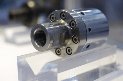
Swivel JointsA swivel joint is a piping joint for supplying water, air, oil, or other fluids to a machine part that performs rotary motion or linear motion in the vertical, horizontal, or forward/backward directions.
A rotary joint is a similar mechanism. Generally, rotary joints are fittings for continuous rotation and are used for piping in machinery that rotates at high speed, such as the spindle of a machine tool.

Swivel joints, on the other hand, often have a fixed upper limit to the angle at which they can be swiveled, and are installed in machinery that rotates at an angle within a fixed range.

Uses of Swivel Joints

Swivel joints are commonly used in machine tools and construction machinery. For example, a swivel joint is used to supply low-pressure or high-pressure fluid to a slide that moves in a straight line in three directions (X, Y, and Z) within a machine. The angle of the joint changes as it moves, eliminating obstructions to the smooth movement of the slide section.

A movable pipeline consists of several swivel joints and pipes. They are used with a defined range of motion and have applications in iron rolling mills, hot presses, tire presses, die-casting machines, injection molding machines, etc.

Swivel joints are used for hose reels, which can handle low rotational speeds to the extent that they are rotated manually.

In automobiles, they are often used for speedometers, tank lorries, and crane trucks. Swivel joints are sometimes used not only for mechanical equipment but also for piping in buildings with seismic isolation structures.

Principle of Swivel Joint

As a rotating mechanism, a steel ball or bearing is built into the shaft of a swivel joint. To maintain smooth rotation, the swivel joint is generally supplied with a certain amount of grease periodically through a grease nipple.

The space between the shaft and the body is sealed with a packing to prevent fluid leakage. Since higher sealing performance is required for use with high-pressure fluids, types that employ a double-seal system are the mainstream.

The advantage of swivel joints is that the rotating mechanism allows the piping to move freely. On the other hand, it has the disadvantage of weakening the strength of the joint itself due to its split structure, which is divided into a shaft section and a main body. Since the rotating part is subjected to thrust radial loads and moment loads, it must be designed to have sufficient strength.

Other Information on Swivel Joints

1. Swivel Joints Used in Cranes

Swivel joints used for pumping lines of moving parts are also used in heavy machinery such as cranes. Heavy machinery such as cranes are divided into two parts: the lower part, such as caterpillars, which moves, and the upper part, which swivels. Swivel joints connect the upper and lower sections.

The mechanism of the swivel joint enables the movement of heavy machinery such as cranes. A rotary joint with a similar mechanism may also be used. 

2. Swivel Joint Sealing

Swivel joints used in high-pressure lines use O-rings or similar materials as seals on the shaft. Generally, one or two O-rings are used. For high pressure applications, multiple O-rings are used for labyrinths.

3. Piping Installation Method Using Swivel Joint Method

There is a piping installation method that utilizes the mechanism of swivel joints used for moving parts. When the fluid flowing in the piping is hot, the piping is heated and thermal elongation occurs. To absorb this thermal elongation, multiple swivel joints are used in the construction method.

By using multiple 90-degree swivel joints in a piping configuration like a U-bend, each swivel joint moves to absorb thermal elongation. In the case of stainless steel piping, this method is often used because the thermal elongation is larger than that of steel piping. There is also a construction method when thermal insulation is used, and piping is supported by rollers and rubber bands.

カテゴリー
category_usa

AFM’s

What Is an AFM?

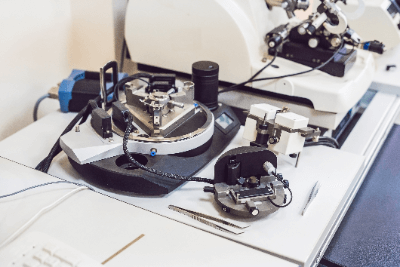
Atomic Force MicroscopesAFMs (Atomic Force Microscopes) are microscopes that visualize the fine surface structure of samples by detecting and scanning the force between a probe called a cantilever and atoms on the sample surface. Unlike scanning tunneling microscopes, which are limited to conductive samples, AFMs can measure a broad range of materials, including insulators and biological samples.

Uses of AFMs

AFMs are primarily used in the industrial field for nanoscale to angstrom-level surface inspection. They are utilized for measuring the uniformity and roughness of semiconductor substrates, inspecting corrosion and degradation of plating on metal electrodes, and observing reactions and structural changes in biomolecules minimally invasively.

Key modes of AFM include:

  • Contact mode: The standard measurement mode in AFM.
  • Non-contact/dynamic mode: Uses cantilever vibration near its resonant frequency, where amplitude changes due to proximity to the sample are monitored.

Principle of AFMs

AFMs measure cantilever displacement caused by atomic forces between the cantilever and the sample surface. Common methods include using a photodiode for displacement detection (optical leverage method) and vibrating the cantilever with a piezoelectric element to monitor amplitude, phase, and frequency. Some AFMs measure the force directly by measuring cantilever flexure, useful for studying membrane proteins and cell mechanics.

What Can Be Learned by Using AFMs

AFMs can detect various forces like attraction, repulsion, adhesion, and binding. They are used in catalysis research and can observe minute particles on surfaces without special treatment. By modifying the tip, AFMs can function as chemical sensors, selectively measuring forces other than atomic forces.

Force Curve of The AFM

Force curves, measured by moving the tip in a reciprocating motion, reflect interaction forces between the tip and the material. These measurements can reveal van der Waals forces, surface tension-based adhesion, and meniscus forces. Force curve measurements have been applied to study the acid-base behavior of solid surfaces.

Difference Between The AFM and STM

An STM offers high atomic resolution in ultra-high vacuum environments but struggles with non-conductive materials and surface contamination. AFMs, on the other hand, can measure non-conductive materials and perform measurements in air, as they detect forces between the material and the tip.

カテゴリー
category_usa

Switched-Mode Power Supply

What Is Switched-Mode Power Supply?

スイッチング電源

A switched-mode power supply (SMPS) is a power supply that incorporates a highly efficient power conversion circuit called a switching regulator.

Electronic devices with ICs and microcontrollers require stable direct current with minimal voltage fluctuation. There are two types of regulated power supplies: linear power supplies and switching power supplies, but linear power supplies have been the mainstream.

In the case of linear power supplies, the circuit is simple. It converts a 100 V AC voltage into a constant AC voltage and rectifies the AC using the diode’s property of forward current flow but not reverse current flow. It further uses a capacitor to smooth it out. However, this had the disadvantage that it did not allow power supplies to be made smaller or more efficient.

Switch-mode power supplies have solved this problem. While linear power supplies convert commercial alternating current into voltage and then rectify it, switched-mode power supplies rectify commercial alternating current into direct current and then convert it into voltage, which is exactly the opposite method.

Then, by switching on and off, it is converted into pulse wave AC and fed into a high-frequency transformer, which is the mechanism of a switched-mode power supply. The characteristic of switching power supplies is that they are smaller and lighter, but their circuits are more complex.

Applications of Switched-Mode  Power Supplies

Compared to conventional linear power supplies, switched-mode power supplies have much more complex circuits, but they have the advantage of being extremely compact due to the use of IC stabilization circuits. Since a large and heavy power transformer (a device that uses electromagnetic induction to convert the height of AC power voltage) is not installed, as is the case with simple power supplies, the size and weight of the power supply can be reduced.

Because of this miniaturization and light weight, applications for switching power supplies include AC adapters for cell phones. They are also highly compatible with small electronic devices such as PCs and tablets, which are often carried around.

Recently, in order to further promote miniaturization, high-power and high-efficiency GaN devices have been incorporated into switching power supplies for AC adapters to realize AC adapters that are even smaller than conventional Si devices.

Principle of Switched-Mode  Power Supplies

The principle of switched-mode power supplies is the opposite of that of conventional linear power supplies. Linear power supplies use a transformer to convert commercial current to voltage and then rectify it, whereas switched-mode power supplies rectify commercial alternating current to DC first and then convert it to voltage. However, once rectified, voltage conversion cannot be performed using a transformer.

Therefore, in a switched-mode power supply, the rectified current is converted into pulse-oriented AC by high-speed switching of semiconductor elements such as transistors and MOSFETs, and fed into a high-frequency transformer. This increases the number of components and circuits required and makes them more complex, but this complexity is the key to switching power supplies.

There are several types of control methods for switched-mode power supplies, but a typical one is the pulse width modulation (PWM) method. This method stabilizes the voltage by adjusting the on-time of the switching on/off cycle, or the width of the pulse wave, so that the area of each pulse is the same. It can be said that switching power supplies allow the output to be adjusted by switching on and off, which is another feature that increases efficiency.

In addition, the pulses of a switched-mode power supply have a high frequency of tens to hundreds of kHz, so a small and light transformer is all that is required. However, high frequencies increase the loss of the iron core, so a ferrite core is used. This increases the efficiency of the power supply and saves energy.

The ferrite core is attached to a core rod of a material called ferrite that wraps the cable, which absorbs the magnetic field generated by the high-frequency noise current flowing through the cable and converts it into heat, thereby reducing noise.

The weak point of switched-mode power supplies is the generation of noise due to high-speed switching, which is expected to be reduced by ferrite technology.

Other Information on Switched-Mode Power Supplies

Frequency of Switched-Mode Power Supplies

Switching power supplies convert output voltage to a specified voltage value by adjusting the ON/OFF time for switching operation by semiconductor devices. The frequency of the signal that controls this ON/OFF switching is called switching frequency. 

Reason Why 24V Voltage Is Often Used

In electrical products that use switched-mode power supplies, the output voltage required for the power supply is often 24 VDC. The reason for this is that control circuits require that voltage, although there are various theories.

One theory is that since DC was once often powered by batteries, it was determined by an integral multiple of the 1.5V of a dry cell battery cell. In small devices, 6V, 9V, 12V, etc. are also used, but these are also integer multiples of 1.5.

In the days before PLCs (programmable controllers) replaced control circuits used in factory automation, circuits consisted of electromagnetic relays, and the voltage was used to turn on the relays. As a remnant of this, 24V is still often used today. There are also other reasons such as the fact that 24VDC is more resistant to noise environments. 

Noise of Switched-Mode Power Supplies

Switched-mode power supplies use switching elements to turn current on and off at high speed, so it is inevitable that they generate high-frequency noise. In the history of the development of switched-mode power supplies, noise suppression has been an essential issue as well as increasing efficiency. Nowadays they are equipped with various noise countermeasures.

Switched-mode power supplies are themselves noise sources. Noise is not only added to the output power line, but also becomes electromagnetic waves that affect electronic equipment.

Noise suppression measures include:

  • Reflection
  • Filtering inductors and capacitors to prevent the transmission of noise components
  • Absorption
    Absorb noise with ferrite cores, etc., and convert it into heat or other energy
  • Bypass
    Dropping noise to ground with capacitors, etc.
  • Shield
    Radiated noise components are dropped to the ground with a metal case or absorbed with a ferrite material or other radio wave absorbing material

Detailed Examples of Noise Suppression 

Common mode noise and differential noise are two of the most common types of noise.

Common mode noise:
This is noise that leaks through parasitic capacitance generated between the switching power supply circuit board and the equipment chassis, and returns to the power supply side through the GND (ground) as a loop path. It is called differential noise because the direction of the noise current at the positive and negative poles of the power supply is the same for each.

Differential noise:
In this case, the current noise from a noise source in series with a switching power supply circuit returns to the power supply side via the power supply line. As the name implies, the direction of each noise current at the positive and negative poles of the power supply is opposite, and is also called normal mode noise.

Generally speaking, common mode noise is the more radiated of the two types of noise, but countermeasures must be taken for both if the allowable noise level is exceeded. The first method is to shorten the cable length of the path or to use stranded cables.

For more serious countermeasures, a noise filter must be added. Choke coils are effective against common-mode noise. A bypass capacitor to ground, called a pass capacitor, is also used. Differential noise suppression is achieved by connecting capacitors between power lines flowing in opposite directions.