カテゴリー
category_usa

FFT Analyzers

What Is a Fast Fourier Transform (FFT) Analyzer?

Fast Fourier Transform (FFT) Analyzers

A fast Fourier transform (FFT) analyzer is an instrument that performs an FFT analysis. Various types of vibration can occur in machinery and buildings and the FFT analyzer can be used to determine the cause of the vibration and ways of reducing it.

While spectrum analyzers and memory recorders are similar instruments to the FFT analyzer, the FFT analyzer is mainly used to observe the frequency components of low-frequency signals.

Uses of Fast Fourier Transform (FFT) Analyzers

FFT analyzers are often used for vibration analysis of machinery, equipment, and buildings. Acceleration pickups are attached to the object to be measured, converted into electrical signals, and input ted into the fast Fourier transform (FFT) analyzer for processing and analysis of the frequency components. By checking the vibration and resonance frequencies generated by machines and buildings, it is possible to reinforce the structure and suppress vibration in order to prevent fatigue failure. Changing the order this way clarifies the causal relationship between reinforcing the structure, suppressing vibration, and preventing fatigue failure.

Another use is in the uneven rotation of motors: FFT analysis of motor vibration can be used to determine the source of vibration. For example, it can help to determine whether the vibration is coming from the motor’s rotating shaft (rotor),  the gears, or the bearings.

Another area where FFT can be used is in speech analysis. It can be used to identify the sound regions produced by people or musical instruments, or to analyze the frequency of noise to determine the location and equipment from which the sound is emanating. In this case, the sound is passed through an amplifier using a microphone, and the signal is converted and amplified for FFT analysis.

Recently, the development of office equipment and home appliances is another area where FFT is utilized, for example in evaluating the quietness of products and studying noise sources and their countermeasures. Since it is also used to identify noise sources for low-frequency signals, it is also applied to noise countermeasures for products that handle frequency signals.

Principle of Fast Fourier Transform (FFT) Analyzers

The fast Fourier transform is based on the theory of the Fourier series proposed by the French mathematician Jean-Baptiste Joseph Fourier. The theory of Fourier series states that any complex waveform with periodicity can be represented by a series of simple sine (sin) and cosine (cos) waves.

In general, it is not known how much of the signal to be actually measured is periodic. Therefore, the Fourier transform cuts an appropriate amount of time from the observed waveform and assumes that the cut waveform is an infinitely repeating signal. In the early days of the Fourier transform, the calculation of the Fourier transform required an enormous number of multiplications. However, J.W. Turkey and J.W. Cooley proposed a method to reduce the number of calculations by taking the number of data to the nth power of 2. For example, if the number of data is 1,024, the number of calculations is reduced from 1,024 × 1,024 = 1,048,576 times to 10,240 times. This method is called the Fast Fourier Transform, and FFT is its acronym.

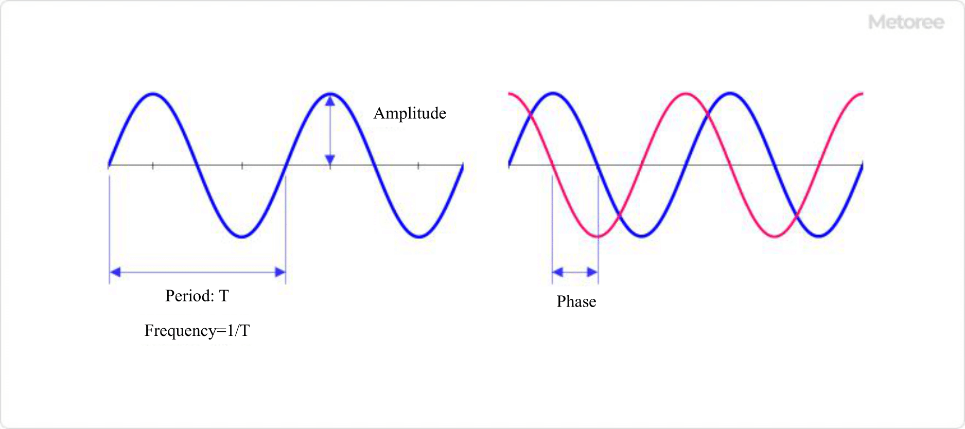
A typical waveform can be represented by three parameters: amplitude, frequency (or period), and phase (time difference). By applying FFT to this principle and using an FFT analyzer, an input waveform signal with time on the horizontal axis is transformed into a graph with frequency on the horizontal axis and amplitude of the waveform at each frequency on the vertical axis.

Difference Between a Fast Fourier Transform (FFT) Analyzer and a Spectrum Analyzer

The first difference between an FFT analyzer and a spectrum analyzer is the range of frequencies they can handle. Spectrum analyzers handle a very wide frequency range of 10 kHz to 10 GHz. Some recent models can handle up to 50 GHz.

Another difference in usage is that fast Fourier transform analyzers are used when it is not known what frequency components are present, whereas spectrum analyzers are used to analyze the frequency components of known high-frequency signals (e.g., cellular phones and Wi-Fi transmitters).

Looking at the difference between the two in terms of the structure of the devices, a spectrum analyzer conventionally consists of analog circuits, whereas an FFT Analyzer uses an AD converter to digitize the obtained waveform and then performs an FF process to calculate the frequency and intensity distribution.

カテゴリー
category_usa

Infrared Lamp

What Is an Infrared Lamp?

Infrared Lamps

Infrared lamps are lamps that produce infrared light by suppressing visible light.

To reduce visible light, the temperature of the filament is made lower than that of lighting lamps to generate more infrared light. Infrared light raises the surface temperature of materials, so they are used for drying and heating items, agricultural products and livestock.Some medical devices use the warming effect to relieve muscle, fatigue and nerve pain.

Shapes of infrared lamps include lamps with light bulbs or quartz tubes attached, and there are also lamps for small sensors.

Infrared Lamp Uses

For home use, infrared lamps are used in electric heating devices and fixing toner in copy machines.

Infrared lamps are warm materials, so they are also used in beautification and for medical applications such as blood circulation and perspiration, as well as in rehabilitation equipment.

Infrared lamps with halogen heaters in quartz glass tubes are often used for industrial applications. They have a wide range of applications, including drying of paint, heating of food, livestock, agriculture, in heating furnaces, as well as semiconductor manufacturing equipment.

Small infrared lamps are also used as light sources for carbon dioxide sensors, which are used to measure CO2 gas in automobiles and for gas and fire detection.

Principle of Infrared Lamps

Light bulbs emit light of various wavelengths, and those that emit more infrared wavelengths are called infrared lamps.

Infrared wavelengths vibrate molecules and generate frictional heat, which can be used to efficiently heat and dry materials in a non-contact manner.

There are three types of infrared lamps: incandescent, LED, and halogen bulbs.

1. Incandescent Bulbs

It makes use of a tungsten filament. By keeping the filament temperature of the bulb at around 2500 K, which is lower than that of a normal incandescent bulb, more infrared rays are generated. Aluminum is deposited inside the glass bulb so that infrared rays are reflected efficiently.

2. LED Light Bulbs

These bulbs are small and power-saving but have low intensity. Because of their small size, they are used as sensor components.

3. Halogen Heater (halogen lamp)

A quartz glass tube is filled with halogen and rare gases; which are both heated by a tungsten filament.
Due to the halogen effect, these lamps last longer than ordinary incandescent lamps and are more compact. They are highly efficient, emitting more than 85% of their power as infrared rays.

The Lifespan of Infrared Lamps

This section describes the life span of “halogen lamps,” which are the most widely used infrared lamps.

Halogen lamps reach the end of their life span when the tungsten used in the electrodes evaporates under the influence of usage conditions and the environment, which leads to deterioration and wear and, consequently, disconnection. Under perfect conditions, the tungsten is evaporated by the circulating halogen and regenerates at its original location, resulting in an unlimited life span, but the following factors result in a finite life span.

The first factor is the “incomplete retention” of halogen. Inside quartz tubes, halogens circulate by creating retention due to the heat generated by the tungsten. At this time, it is impossible to generate a complete circulation that returns the evaporated tungsten to its original position in the filament, and the incomplete circulation causes the tungsten to wear out and break.

The second factor is the “uneven temperature distribution” of the filament. Due to the shape of the filament and the retention of halogen, it is inevitable that the temperature distribution of the filament will be non-uniform. As a result, evaporation accelerates in the hotter parts of the filament, resulting in wire breakage and a shorter life span.

The third factor is vibration and shock. The strength of tungsten filaments, which generate heat, is reduced. Therefore, external vibrations and shock accelerate evaporation and disrupt convection currents, which in turn accelerates wear and tear and causes incomplete recirculation, resulting in a shorter life span.

Effects of Infrared Lamps

Far-infrared radiation emitted from infrared lamps has been shown to have a beneficial effect on the human body. This effect occurs when the wavelengths of far-infrared radiation pass through the skin to reach the internal parts of the body, where they warm the body from the inside by resonance with the cells.

The effect expands blood vessels promoting blood circulation, and in addition to relieving fatigue. It is also effective for coldness, stiff shoulders, and relieving of back pain. Because it warms the body from the inside, it is said to be more effective than acupuncture and moxibustion, which transmit heat from the surface of the skin.

In the field of dentistry, it has been widely used for its effectiveness in relieving muscle tension, from dry mouth massage and facial stress relief during oral treatment of facial distortion.

カテゴリー
category_usa

Frequency Counter

What Is a Frequency Counter?

Frequency Counters

222_Frequency-Counters_周波数カウンタ-1.png

Figure 1. Three parameters of an electrical signal waveform

A frequency counter is a digital device used to measure the frequency occurring in an electronic circuit.

An electrical signal can be expressed in terms of three parameters: frequency, amplitude, and phase. It is also possible to determine the period by the reciprocal of the frequency. Frequency measurement is an important parameter in the basic measurement of electrical signals.

In addition to the frequency counter, those with several additional functions, such as duty cycle measurement, pulse rise time, and time interval, are called universal counters.

Uses of Frequency Counters

Frequency counters are used as basic measuring instruments in electrical signal measurement, like ammeters and voltmeters. Although some products are available as stand-alone frequency counters, many products have been developed with frequency counter functions as part of the functions of devices with many functions, such as digital multimeters, oscilloscopes, and optical spectrum analyzers.

Frequency counters are characterized by the fact that their principle is very simple. Since it is possible to make your own frequency counter, kits are available. Frequency counter kits are available from various companies for several tens of MHz. The reason for this is that direct-type frequency counters are characterized by their uncomplicated operation.

Some multi-testers are equipped with a frequency measurement range, and these types are especially useful at sites where large measurement equipment cannot be brought in, because they can be handled easily. However, while they have the advantage of being easy to use, their disadvantage is that they are not suitable for applications that require high frequencies or a large number of significant digits.

Since most of the kits are LSI-based, you cannot learn the entire structure, but you can get a feel for it.

Principle of Frequency Counter

222_Frequency-Counters_周波数カウンタ-2.png

Figure 2 Principle of frequency counter (Direct method)

A frequency counter consists of a waveform shaping circuit, a gate, a crystal oscillator, and a counting circuit.

1. Waveform Shaping Circuit

Converts the input signal into a “pulse train.”

2. Crystal Oscillator

Generates pulses with a fixed time width. Generates a time window (gate time) for measuring the pulse train described earlier, and the time window serves as a window for measuring the frequency.

3. Measurement Circuit

The frequency of the original signal is measured by counting the number of pulses in the time window. The resolution of the frequency measurement is determined by the time width of the time window generated by the crystal oscillator. For example, a time window of 1 second allows the frequency to be displayed in units of 1 Hz, a time window of 0.1 second is 10 Hz, and so on. The resolution is proportional to the inverse of the time window width.

In frequency counters, the most error occurs at the point where the pulse train is generated, especially if the input signal contains noise, which can cause the rising edge of the pulse to be unstable or generate extra pulses that should not be there.

The method used to prevent the generation of errors is to perform repeated measurements and average out the noise components. This reduces the errors that occur when generating pulse trains.

Frequency Counter Measurement Method

222_Frequency-Counters_周波数カウンタ-3.png

Figure 3. Frequency counter system

A frequency counter is a device that measures the frequency of an input signal and displays the result. There are two measurement methods: the “direct method,” which has been used for a long time because it is easy to implement, and the “reciprocal method,” which is expensive but can obtain a high number of significant digits.

1. Direct Method

Zero Point Cross Measurement
The direct method frequency counter measures the number of times the frequency of the input signal crosses at the zero point. If the input signal is a sine curve, it counts the number of times it crosses either down or up to the zero point. The advantage of the direct method frequency counter is that it can be easily implemented using only hardware. For this reason, this method has been used for a long time, and its number of zero point crossings per second is displayed as a frequency measurement.

The direct method frequency counter is characterized by the fact that an accurate reference clock is made inside the device, and the number of times the zero point is crossed is measured by opening a time window for that amount of time.

Number of Significant Digits in Measurement
The number of significant digits in a direct method frequency counter is determined by the time width of the time window and the input frequency. For example, if the input frequency is 1 GHz and the time window is 1 second, the measured value is 1×10^9 and the number of significant digits is 10. If the input frequency is 1 kHz, the number of significant digits is 4, and the resolution for both is 1 Hz.

For example, if the time window is 100 seconds, the number of significant digits is 6 at 1 kHz, and the resolution is 0.01 Hz. However, taking at least 100 seconds for a single measurement is not realistic and significantly reduces workability. It should also be used with the understanding that the measured value will always have a quantum error of ±1.

If you are only measuring high-frequency signals, you can use a direct method frequency counter without any problems, but to increase accuracy with the direct method, you need to increase the time window time width. However, the direct method has the disadvantage of extremely low efficiency because the longer the time window, the longer the time required for each measurement. Frequency Counter of “Reciprocal Method” is an alternative in such a situation. 

2. Reciprocal Method

A reciprocal frequency counter counts the input waveform as it is or divides it by an internal reference clock. The advantage of this method is that a high number of significant digits can be obtained, especially when measuring low frequencies. The number of significant digits in a reciprocal Frequency Counter is determined by the internal reference clock and gate time, and is not affected by the input frequency.

For example, if the internal reference clock is 10 MHz and the gate time is 1 second, the number of significant digits is 7. Although the reciprocal method is capable of obtaining a high number of significant digits in measurements in the low frequency counter range, it has the disadvantage of being expensive because the operation of the counter itself is complex.

カテゴリー
category_usa

Vacuum Tubes

What Is a Vacuum Tube?

Vacuum Tubes

A vacuum tube, or electron tube, is a hollow device with a highly vacuumed interior and enclosed electrodes. It controls electrons through electric and magnetic fields to amplify, detect, rectify, oscillate, and modulate them.

Vacuum tubes consist of a container made of glass, metal, or ceramics. This container houses multiple electrodes in a vacuum or low-pressure environment, often with a small amount of rare gas or mercury.

The tubes are categorized based on their electrodes: bi-polar, tri-polar, quadrupolar, or pentode. Rectifier tubes, a type of 2-pole tube, are specifically used for rectification.

Uses of Vacuum Tubes

Vacuum tubes were once fundamental in electrical and electronic circuits for rectification, modulation, detection, and amplification. However, semiconductor elements have largely replaced them. Still, they are produced for broadcasting stations, the military, and particularly for audio and guitar amplifiers due to their excellent sound quality.

Special vacuum tubes like magnetrons continue to be important for generating microwaves in microwave ovens and radar.

Advanced applications include X-ray tubes, photomultiplier tubes (PMTs) for optical measurements, and image intensifiers for night vision.

Principle of Vacuum Tubes

Vacuum tubes operate on thermionic emission, where materials emit electrons when heated in a vacuum. In a bipolar vacuum tube, heating the filament emits electrons. Applying a positive potential to the plate attracts these electrons, allowing current to flow.

The triode vacuum tube has a grid between the plate and the filament. Adjusting the grid’s potential controls the electron flow, enabling amplification.

Quadrupole, pentode, and beam tubes are evolved versions of the triode, offering enhanced performance.

Types of Vacuum Tubes

Vacuum tubes come in various types, each suited for specific purposes.

1. Audio and Guitar Vacuum Tubes

Primarily used in amplifiers for enhancing music and instrumental signals.

2. Transmitter Tubes

Crucial in transmitters for radio communication, broadcasting, and industrial high-frequency generators.

3. Cathode Ray Tubes (CRT)

Integral in devices like cathode-ray tubes for image display.

4. Magnetron

Key in microwave generation for radar and microwave ovens.

5. Imaging Tubes

Formerly used in TV cameras, now prevalent in nuclear reactor decommissioning due to radiation resistance.

6. Night Vision Tubes (Image Intensifiers)

Utilized in night vision devices and goggles.

7. X-ray Tubes

Employed in dental and industrial X-ray inspection tools.

カテゴリー
category_usa

Quartz Crystal

What Is a Quartz Crystal?

A quartz crystal unit is a passive element that vibrates at a specific frequency and is sometimes referred to as a piezoelectric or piezoelectric element. Initially, natural quartz crystals were used, but as demand increased, they were replaced by synthetic quartz crystals, such as silicon dioxide, barium titanate, and Rochelle salt.

Piezoelectric elements, in combination with oscillation circuits, are built into household appliances such as cellular phones, televisions, and digital cameras, as well as electronic devices such as automobiles and medical equipment. Quartz crystal units’ thickness and cutting method vary depending on the frequency range used. For example, the cutting method known as AT cut can be used to obtain quartz crystal units with frequencies ranging from 1 to 300 megahertz and usable in a wide temperature range.

Principle of Quartz Crystals

The piezoelectric crystal is a material in which a surface charge proportional to pressure appears when pressure is applied in a specific direction. The phenomenon in which a surface charge is generated in proportion to pressure is called the piezoelectric effect or piezoelectric phenomenon. Conversely, the phenomenon in which the crystal is deformed by the application of voltage is called the reverse piezoelectric effect. Quartz crystals were literally made from natural quartz crystals in the beginning, but nowadays, synthetic quartz crystals are used to meet increasing demand. Silicon dioxide, potassium titanate, Rochelle salt, and other materials are used instead.

Quartz crystals have electrodes attached to them, and an electric current flows through them from an external source. The surface charge of the quartz crystal changes in accordance with the phase of the current, causing periodic deformation of the quartz crystal. Quartz crystal units utilize the vibration phenomenon caused by this periodic shape change.

Applications of Quartz Crystals

Quartz crystal units are used in a variety of household electronic devices such as cell phones, televisions, digital cameras, and personal computers. In addition, they can also be found in automobiles and medical equipment because they are stable with slight frequency fluctuation. Oscillation circuits based on quartz crystal units are much more accurate than other oscillation circuits on the ppm order.

Generally used quartz crystal units are cut very thin, with thicknesses ranging from 20 to 50 micrometers. In addition, electrodes are attached to the plate surface of the quartz crystal unit for connection to external terminals and electrodes. The thickness of the quartz crystal and the surface from which it is cut vary depending on the functions required of the quartz crystal.

Frequency of Quartz Crystals 

The frequency of a quartz crystal unit varies depending on the way the crystal is cut and its thickness. The frequency also varies depending on the cutting method. For example, the “AT cut” method can produce quartz crystals that can be used in a wide temperature range, corresponding to frequencies from 1 to 300 megahertz.

The “BT cut” method, which has a different cutting angle, can be used in the frequency range of 7~38 megahertz, and the amount of frequency change in response to temperature is different compared to the AT cut method. In addition, quartz crystals cut into a tuning fork shape can handle 32.768 kilohertz and are used in clocks.

Load Capacitance

When incorporating a crystal unit into a circuit, it is necessary to match the load capacitance of the circuit and the crystal unit. Load capacitance is the value of equivalent capacitance in virtual series when looking at the oscillation circuit from the crystal unit side. Since the frequency variation in response to changes in load capacitance varies depending on the value of load capacitance, it is necessary to incorporate a crystal unit with appropriate load capacitance to stabilize the circuit.

When a crystal unit is actually used, the circuit is matched based on the crystal unit’s oscillation frequency, tolerance deviation, and load capacitance value. However, in an actual circuit, there are stray capacitances generated by various factors, which may cause a deviation from the nominal load capacitance of the crystal unit. Therefore, after determining the difference between the oscillation frequency when the crystal unit is built into the circuit and the standard load capacitance oscillation frequency, adjustment is made by fine-tuning the capacitance of the circuit to bring the difference close to zero.

カテゴリー
category_usa

Cable Ties

What Is a Cable Tie?

Cable Ties

A cable tie, also known as a bundling band, is a band made of plastic used to bundle and organize multiple cables, tubes, etc. Once applied, they are designed to be secure and non-removable, although some types can be re-bundled.

Cable ties are known by several names including bundling ties, cable ties, and wiring bands. Other terms like interlock and interlock tie are registered trademarks of Helaman Tighten, and thus, are specific to that brand.

Uses of a Cable Tie

Cable ties are primarily used for bundling items such as wiring and tubing to improve manageability. They can be used to group multiple wires or pipes, or attached to a fixture to prevent movement of the cables or pipes.

Usage involves wrapping the tie around the object and threading the tail through the head. Once it clicks into place, the serration or jagged edge catches on the claw in the head, securing the tie. Due to their strength, cable ties require cutting tools like nippers for removal.

How to Choose a Cable Tie

The key factor in selecting a cable tie is its size. A small tie may not be sufficient for larger bundles, and a large tie could be cumbersome for smaller items. It’s important to match the size of the tie to the items being bundled.

Material is another important consideration. Different materials offer varying levels of strength, heat resistance, and chemical resistance. Choose the material based on the intended use, location, and environmental conditions. Colored ties are also available for identification purposes, helping to easily locate connection points of wires or hoses.

Recently, Velcro tape types have become popular for their ease of use and adjustability. While not suitable for heavy loads or vibrations, Velcro ties are ideal for light-load binding due to their reusability and ease of adjustment.

カテゴリー
category_usa

CPU Cooler

What Is a CPU Cooler?

Central Processing Unit (CPU) Coolers

A CPU cooler is a component used to cool the CPU of a computer, such as a PC, etc. Since the CPU generates heat during operation, problems such as thermal runaway, in which the semiconductors inside the CPU do not operate properly, can occur if the CPU is not cooled appropriately. For this reason, CPU coolers are installed according to the power consumption of the CPU.

There are two main types of CPU coolers: air-cooled and water-cooled. Most of the CPU coolers in PCs on the market are air-cooled, while water-cooled coolers are often used in home-built PCs.

Usage of CPU Coolers

CPU coolers are used by attaching them to the CPU. It is installed in most models of desktop and notebook PCs on the market. The sound of the wind when the computer is in use is due to the electric fan operating to release the heat generated by the CPU into the atmosphere.

Other than commercial PCs, CPU coolers are sold separately to build your own PC.

Principle of CPU Cooler

The components of an air-cooled CPU cooler are a base plate, a heat pipe, a heat sink, and an electric fan. The heat path from the CPU to the air is in the order of CPU → base plate → heat pipe → heat sink → air. Heat pipes and electric fans are sometimes omitted.

The materials and structure of CPU coolers are designed to dissipate heat efficiently. Copper and aluminum alloys are used as materials for the components in consideration of thermal conductivity and heat transfer coefficient to the air. In order to efficiently transfer heat from the CPU to the base plate, thermal conduction grease is applied to the contact surfaces.

To dissipate heat from the heat sink to the air, many CPU coolers use an electric fan to generate a forced airflow. The electric fan’s airflow is used to cool the heatsink and other elements on the motherboard (board), such as memory. The airflow inside the case is also designed with airflow considerations in mind, as the air that the heat sinks have heated must be discharged smoothly to the outside of the computer case.

The size of the heat sink is essential to increase the heat dissipation capacity of the air-cooled system. A large heat sink is required to cool a CPU with high power consumption, but the installation space in the case limits the size of the heat sink.

The components of a water-cooled CPU cooler can be thought of as replacing the heat pipes that play the role of heat conduction in air-cooled systems with cooling water hoses and the heat sinks for dissipating heat with radiators. Since radiators can be installed outside the case, they can be easily increased in size, and cooling capacity can be easily improved. However, there is a risk of failure due to cooling water leakage.

カテゴリー
category_usa

HDD

What Are Hard Disk Drives?

Hard Disk Drives

Hard Disk Drives (HDDs) are typical external storage devices. It is a non-volatile storage device that retains data even when the power is turned off.

The structure consists of multiple metal disks with magnetic materials stacked on top of each other. Data is read and written by rotating the disks at high speed and magnetizing the magnetic material by bringing a magnetic head close to it.

Since the magnetic head and disk are brought into close proximity when reading and writing data, the structure is vulnerable to vibration. Because of the large amount of data handled, high-speed

communication is required for the connection, and standards such as SCSI, IDE, and SATA are used. In the past, cables using SCSI and SATA standards were often used to connect external HDDs.

However, in recent years, as data transfer speeds have increased through USB connections, USB is increasingly being used to connect external HDDs.

Usage of Hard Disk Drives

Hard Disk Drives are often used as mass storage devices to store data on PCs. In addition to PCs, hard disks are also widely used in electronic devices such as external storage devices, servers, network drives, hard disk recorders in home appliances, and game consoles.

In recent years, as the capacity of SSDs have increased, they are increasingly taking on the role traditionally played by hard disk drives: HDDs use magnetic disks, while SSDs record data in NAND flash memory, which uses semiconductor elements.

The advantage of hard disk drives over SSDs is that large capacities can be procured at low cost. For this reason, SSDs are increasingly being used as storage devices for frequent read/write operations, while hard disk drives are being used as secondary data storage devices.

Principle of Hard Disk Drives

A hard disk generally consists of a disk, motor, magnetic head, and control circuit.

In a hard disk, a single disk is called a platter. The surface of the platter is coated with magnetic material, which is used to magnetically record data. In order to obtain the data capacity, multiple platters are generally stacked on top of each other.

Hard disks are equipped with motors to operate them. There are two types of motors: one is the motor that spins the platters. This is called a spindle motor. The faster this motor can rotate, the faster data can be read and written, so the number of revolutions is sometimes used as a performance indicator.

The other motor drives the arm that moves the magnetic head. The magnetic head is what reads and writes the data on the platters in a hard disk. Since there are multiple platters, magnetic heads are mounted according to the number of platters. The principle of writing data is to apply a magnetic force to the magnetic material on the platter surface using an electric current.

Which direction the magnetic force (the direction of the S and N poles of the magnet) is facing corresponds to the 0 and 1 information in the digital record. When reading, data is read based on the resistance value that changes under the influence of the magnetic field on the platters.

How to Select Hard Disk Drive

There are different points of focus for selecting an internal hard disk drive and an external HDD.

1. Internal Hard Disk Drive

You may purchase an internal hard disk drive to build your own computer or to improve the performance of your desktop computer.

First, check the connection standard (IDE or SATA) of the environment in which you intend to build or replace the HDD, and choose one that fits.

Next, choose a disk size between 3.5″ and 2.5″. 3.5″ is generally for standard desktop PCs, while 2.5″ is for notebook PCs or space-saving desktop PCs. A 2.5″ disk can also be installed by installing a mounter in the 3.5″ space of a desktop PC.

Select the capacity that best suits the intended use. Unnecessarily large capacities will increase the cost.

The most common disk rotation speeds are 7,200 rpm and 5,400 rpm. The higher the speed, the faster data can be read and written, but it is also more expensive and generates more heat. It is advisable to select a disk drive based on the application and whether or not high speed read/write speed is required.

2. External Hard Disk Drive

There are two types of external hard disk drives: stationary and portable. The stationary type is heavy and not suitable for carrying around, but inexpensive, while the portable type is lightweight and is designed to protect against shocks while being carried around.

The interface to be connected to an external hard disk drive is selected based on the device to be connected. Connection standards include USB, Thunderbolt, and eSATA, etc. Since the transmission speed of USB, etc. varies greatly from generation to generation, it is advisable to confirm the use in detail and select one that supports the expected transmission speed.

カテゴリー
category_usa

PCI Board

What Is a PCI Board?

A PCI board, also called an expansion board, is a board that can be connected to a PC to expand the available functions.

They are mainly used in desktop PCs and can be connected to motherboards or other expansion board interfaces. Some PCs may not have an interface for PCI boards.

There are many types of PCI boards on the market, and the functions that can be added vary from board to board.

Uses of PCI Boards

There are many different types of PCI boards, but the most common types are as follows.

    • Graphic cards: Allow expansion of connectors for connecting a PC to a monitor.
  • Network boards: Allow expansion of connectors for LAN, fiber optics, etc., to the PC.
  • Soundboards: Extend the audio interface to your PC.
  • Storage boards: Allow expansion to control storage on a PC.
  • For external interface: You can add an external interface such as a USB.
  • Tuner: You can extend a PC with a digital terrestrial tuner, etc.

Principles of PCI Boards

PCI boards come in various standards, and care must be taken to select the right PCI board for your PC, or you will not be able to connect correctly.

The most common standards are PCI and PCI Express. Recently, PCI has been less commonly used, and PCI Express is the mainstream.

Within PCI Express, the standard is subdivided according to the number of lanes, and the number of connector pins and connector cutout positions at the connection varies. The higher the number of routes, the faster the communication speed.

PCI also comes in two sizes: regular PCI and LowProfile PCI. LowProfilePCI is often used for space-saving PCs and cannot be installed with standard PCI. Standard PCI and LowProfilePCI have different board sizes and bracket sizes.

Also, some types of PCI boards use two or more brackets, and if there is not enough space for the brackets, the board may not be able to be installed.

カテゴリー
category_usa

X-ray Tube

What Is an X-Ray Tube?

X ray Tubes

An X-ray tube is a type of X-ray generation tube that converts electrical input power to produce X-rays.

X-Ray Tubes are classified into two types according to the type of tube: sealed tubes, in which the inside of the tube is always kept in a vacuum, and open tubes, in which a vacuum pump is installed on the outside of the tube to create a high vacuum.

Sealed tubes are also known as anode tubes. They are further classified into two types: rotating anode tubes with a rotating anode and fixed anode tubes without a rotating anode. The fixed-anode tube has a rotating anode, which allows heat dispersion and increases the current flowing through the X-ray tube.

X-Ray Tubes are classified into microfocus and mini-focus (or millifocus) types, depending on the focal spot size. These X-ray tubes have a focal spot size on the order of microns and millimeters, respectively.

Uses of X-Ray Tubes

X-Ray Tubes are used as X-ray generators in various fields. X-rays are electromagnetic waves with a wavelength shorter than that of ultraviolet rays, and their high energy allows them to penetrate through materials.

The following are some of the applications that take advantage of this penetrating effect:

  • Medical field
    General radiography, mammography, CT examinations, X-ray therapy used in cancer treatment, etc.
  • Scientific and industrial fields
    X-ray diffraction, X-ray fluorescence analysis, nondestructive testing, thickness and other material testing, airport baggage inspection, etc.

Principle of X-Ray Tubes

An X-ray tube consists of an enclosure, a cathode, and an anode . When a high voltage is applied between the cathode and anode after the cathode filament is heated by an electric current, hot electrons are emitted from the filament and are directed to the anode target at high speed.

1. X-Ray Driven

The thermal electrons are attracted to the nucleus of the anode material, such as tungsten, and rapidly change direction, releasing energy. At this time, 99% of the energy is converted to thermal energy, but the remaining 1% is emitted as X-rays. These X-rays are called bremsstrahlung X-rays and are characterized by their continuous spectrum.

Where the thermal electrons pass in relation to the nucleus is not uniquely determined, and the X-ray intensity varies depending on where they pass. Therefore, bremsstrahlung has a continuous spectrum.

2. Characteristic X-Rays

Some thermal electrons rarely collide with electrons of the target atom. The collided electrons gain energy from the thermal electrons and are repelled, and then transition to the outer electron orbitals, but because they are unstable, they quickly return to their original orbitals.

The difference in the energy state of the electron orbital is emitted as X-rays. X-ray tubes produce mostly bremsstrahlung X-rays, which are extracted through a window made of beryllium or other material with low X-ray absorption in the tube’s enclosure.

Other Information on X-Ray Tubes

1. Tube Voltage and Tube Current

The intensity and energy of the X-ray tube depend on the tube voltage and current.

Tube voltage
The tube voltage is the voltage applied between the anode and cathode of the X-ray tube. The higher the tube voltage, the shorter wavelength X-ray tube produces. The tube voltage is a parameter that affects the intensity and energy.

Tube Current
The current that flows through the inside of the X-ray tube. The current is generated when thermal electrons generated at the cathode collide with the anode. In a rotating anode tube, the anode rotates to disperse the heat and increase the tube current.

There is a proportional relationship between the tube current and the total X-ray tube intensity. On the other hand, the X-ray energy does not change when the tube current is changed.

2.Transmission Properties of X-Rays

Since X-rays are electromagnetic waves with a very short wavelength, they have the property of transmitting through materials. The transmission rate varies depending on the material, and X-rays are attenuated during transmission.

The higher the energy of the X-ray, the greater its transmission ability.