カテゴリー
category_usa

Pressure Tanks

What Is a Pressure Tank?

Pressure tanks are tanks that hold pressure above atmospheric pressure.

However, pressure tanks store not only gases but also liquids. Liquids are not ordinary water, but ultra-low temperature fluids, such as liquid oxygen and liquid nitrogen.

Since these are gases at room temperature, they must withstand internal pressure to be stored in a liquid state.

Also, the fact that the pressure of a gas is higher than atmospheric pressure means that if a pressure tank is destroyed, the tank will be destroyed in an instant due to the release of the pressure.

For this reason, pressure tanks with pressure or capacity above a certain level are regulated as Class II or Class I pressure vessels.

Uses of Pressure Tanks

Pressure tanks are used in many places, from general factories to chemical plants. For example, a receiver tank for compressed air from a compressor is also a pressure tank. By temporarily holding pressure, pressure fluctuations caused by air usage can be reduced.

In addition, the steel industry, which uses large amounts of nitrogen and oxygen gases, has tanks that store liquid oxygen and liquid nitrogen.

These tanks contain liquid inside, but since liquid nitrogen and liquid oxygen are gases at room temperature, they must withstand pressure tanks to store them in a liquid state. They also have a double-layered outer layer for thermal insulation.

Principle of Pressure Tanks

Most pressure tanks are made of metals such as SS400 and SUS304, although some are made of resins, such as FRP.

Pressure tanks are made up of a body plate and a mirror plate, the thickness of which is calculated based on specifications.

What we have to be careful about here is that the strength concept of the welding part will change depending on the specifications and inspection of the welding joint. For example, if the weld is 100% radiation tested, the strength of the weld will be 1.0, which is the same as the original metal, but if not, the strength will be lower.

This means that the thickness of the plate will be thicker, but it is necessary to consider the cost and time required carefully for testing and how much to do.

In addition, attention should also be paid to the concept of internal pressure and external pressure. There is a difference in the calculation method between internal pressure and external pressure, and the thickness of the plate becomes thicker with external pressure.

If a mistake is made in the calculation of either, it will lead to rupture in the case of internal pressure, and to destruction by crushing in the case of external pressure.

To prevent such accidents, safety valves, and vacuum brake valves may be installed.

カテゴリー
category_usa

Soil Moisture Meters

What Is a Soil Moisture Meter?

Soil Moisture Meters

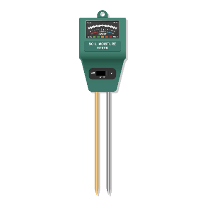
Soil moisture meters are used to measure the amount of moisture contained in the soil. They are mainly used to check soil properties and management conditions in the agricultural field, agricultural research and development, environmental monitoring associated with construction work (vegetation protection, etc.), and personal gardening.

Depending on the principle of measurement, some types use the dielectric constant (TDR, ADR, and FDR methods), tensiometer, and cyclometer methods. There is also a logger type that, when buried in soil, periodically measures data and stores it in the main unit. Since electronic moisture sensors are available at low cost, there are also applications for making your own soil moisture meter.

Uses of Soil Moisture Meters

Soil moisture is widely used as an indicator in agriculture because it is an important factor in determining plant growth. In the case of potted plants and gardening, too high a soil moisture content can cause root rot, so soil moisture meters are widely used by professionals and homeowners alike.

Soil moisture meters are based on a variety of principles and come in a wide price range, so it is necessary to choose the right type for your application and the accuracy of the data you need. Some meters can be purchased for as little as a few dollars per unit, while others cost hundreds of dollars.

Principle of Soil Moisture Meters

The main methods used in soil moisture meters are as follows:

1. TDR (Time Domain Reflectometry) Method, ADR (Amplitude Domain Reflectometry) Method, and FDR (Frequency Domain Reflectometry)

The basic principle of all of these methods is the same: soil moisture is measured by a dielectric constant. Soil consists of water, air, and soil particles (minerals and dead plants and animals). The dielectric constant of each material is much higher for water than for other materials, and the dielectric constant of the soil itself has a constant relationship with the soil water content. The soil moisture content is determined from this relationship. Characteristically, the ADR method is cheaper in equipment and easier to operate than other methods (FDR and TDR). On the other hand, the TDR method or soil is not affected by temperature unless it freezes, making it suitable for use in environments where temperatures are not stable.

2. Tensiometer Method

A container made of unglazed parts called a porous cup, is inserted into the soil for measurement. The container is filled with water, and the amount of water that oozes out is measured as pressure. This method uses the water tension of the soil. This method is widely used in the industrial field, but its disadvantage is that it is time-consuming.

3. Cyclometer Method

This method uses thermocouples in the soil to evaluate the soil. The relative vapor pressure of air in equilibrium with water in the soil is measured to calculate soil moisture. Because it can also measure the moisture content of plant tissue, it has a wide range of applications, but because it is a precision instrument, it is very expensive, costing several thousand dollars per unit.

カテゴリー
category_usa

Rotary Joints

What Is a Rotary Joint?

A rotary joint is a joint that can form a flow path for water, air, oil, etc., between a fixed pipe and a rotating shaft. It is sometimes called a rotary joint or swivel joint.

Rotary joints make it possible to supply fluid continuously to a rotating body and circulate the fluid inside. This function can be used to add functions such as cooling and lubrication to the rotating rolls or to supply power source fluid to equipment on the rotating body.

Uses of Rotary Joints

Rotary joints can supply fluids such as water, air, and oil to rotating bodies. They are used to provide cooling and lubrication functions and power sources to rotating bodies.

A typical example of a cooling application is a cooling roll (chill roll). Cooling rolls are used to cool products on the surface of rolls by circulating a refrigerant such as water or oil inside the rolls that convey sheet products, and rotary joints are used to supply the fluid.

In the steel industry and other industries, a rotary joint may be used to supply oil as a hydraulic power source to a cylinder connected to a rotating winding shaft.

Principle of Rotary Joints

Rotary joints consist of a stationary channel, a rotating channel, and a seal to seal these channels. The stationary channel is located on the axis of rotation or the circumference and is always connected to the rotating channel, thus enabling a continuous fluid supply to the rotating body.

Rotary joints are available from those with one port to those with 20 or more ports. The number of ports is set according to the number of fluids to be used. In cooling rolls, which are often used in factories that handle sheet products, water is the only refrigerant used in most cases. In this case, a rotary joint with two ports is used, one for the outward flow and the other for the return flow. Shield machines used for tunneling require the supply of many fluids, such as mud removal fluid, hydraulic oil, and grease. Rotary joints with many ports are specially designed for this purpose.

The material of the rotary joint must be changed according to the temperature and corrosiveness of the fluid being used. When supplying high-temperature fluids, a product with a high heat-resistant seal should be selected, and when supplying highly corrosive fluids, a stainless steel or copper alloy rotary joint should be selected.

カテゴリー
category_usa

Live Centers

What Is a Live Center?

A live center is a device attached to the tailstock of a lathe to hold a workpiece. The main difference between a rotary center and a fixed center is that the rotary center has a bearing built into the body.

Live centers can only be used for a limited number of workpieces and revolutions because friction is generated between the fixed center and the workpiece as it rotates. This may cause unacceptable damage to the workpiece. Live centers, on the other hand, can hold the workpiece stable while interlocking with the workpiece and can handle high-speed rotation.

Uses of Live Centers

When machining with a lathe, if the workpiece is too long or the chucking area is too small, the spindle rotation and machining load may deform the workpiece, resulting in unstable machining. To solve these problems, live centers support the workpiece from the opposite direction of the chuck.

Live centers can hold the workpiece in conjunction with the spindle because bearings are built into the body of the center. On the other hand, the bearing has the disadvantage of increasing the diameter of the head. When a tool is close to the live center, it is necessary to pay close attention to the interference with the live center.

Principle of Live Centers

Live centers are mounted on the headstock of a lathe. The shank is generally a Morse taper shank that fits the shaft size of the tailstock.

Live centers can be roughly divided into two types.

  • Umbrella Type Live Center
    The tip of the rotary center is shaped like an umbrella. They are used as centers when processing hollow pipe materials.
  • Lace Center
    This is a general live center used as a runout stop when machining bars and blanks on a lathe. The all-steel type, in which the main body is made entirely of the same steel, is the most common type, but there are also types with carbide tips on the tip. Depending on the material of the workpiece, the tip may be damaged by abrasion, so the type with a carbide tip is suitable when higher hardness is required.

Recently, a tip-replaceable type has also become available. This type has a separate live center body and center head. Replacing the center head, there are many advantages, such as easy replacement with a new one and compatibility with a variety of workpieces.

カテゴリー
category_usa

Injection Nozzles

What Is an Injection Nozzle?

Injection nozzles are devices that can inject minute amounts of liquid or gas compressed at high pressure into a fine mist and a space.

Injection nozzles are used in engines to ignite fuel quickly by injecting and vaporizing it or to distribute fuel throughout a closed space.

Uses of Injection Nozzles

Injection nozzles are systems designed to atomize liquids and gases into fine particles, and are used in machinery and equipment that apply these characteristics:

  • Diesel Engine: Since diesel engines use a compression pump to turn diesel fuel into high-pressure fuel and feed it into the engine combustion chamber, the injection nozzle is used as a system to feed high-pressure fuel into the engine combustion chamber through the injector nozzle, which serves as the fuel injection port. To atomize the fuel effectively, various nozzle shapes are available.
  • Direct Injection Gasoline Engines: These nozzles are used in gasoline engines to improve fuel economy, especially in passenger cars and motorcycles.
  • High-Pressure Injection Systems: Injection nozzles are often used for high-pressure liquid and gas injection systems. Injection nozzles are used in high-pressure injection systems for sprinkler systems and machines used for washing and cleaning. Injection nozzle systems are especially used for high-pressure gases for air cleaning and air shower curtains.
  • Machinery and Equipment: Injection nozzles are also used in machinery and equipment for coating and painting, humidification, fire extinguishing, and temperature control, such as heating and cooling.

Principle of Injection Nozzles

Injection nozzles for liquid jetting can be broadly classified into two types: one-fluid nozzles and two-fluid nozzles. One-fluid and two-fluid nozzles differ in the method used to refine the liquid. One-fluid nozzles use liquid pressure to push the liquid into the nozzle, while two-fluid nozzles use fluid flow to grind the liquid itself into particles, which are then ejected from the nozzle.

Injection nozzles for gas injection, such as compressors and blowers, have different mechanisms depending on the application.

Types of Injection Nozzles

Injection nozzles typically consist of a nozzle body and a needle valve. There are various types, including:

  1. Hole Nozzle: Designed at a certain angle (jet angle) to spread the fluid.
  2. Throttle Nozzle: Designed with a throttle opening to control the injection amount.
  3. Pin-Tow Nozzle: Designed for installation in a vortex chamber with a secondary jet opening in the nozzle body.

Features of Injection Nozzles

Injection nozzles offer several features, including:

  • Fine Atomization: Achieves fine atomization of liquids.
  • Penetration: Ensures that the atomization reaches every corner of an enclosed space.
  • Dispersion/Distribution: Disperses and distributes spray over a wide area.
  • Oil Tightness: Prevents leakage of gas or liquid at the end of spraying.

These features make injection nozzles versatile in various applications, improving fuel efficiency, controlling temperature, and more.

カテゴリー
category_usa

Breath Analyzers

What Is a Breath Analyzer?

Breath analyzers are devices that can detect and analyze the volume and concentration of oxygen and carbon dioxide in the exhaled breath. They are worn on the user’s face like a gas mask, so they can be used in various exercise activity conditions.

Breath analyzers can measure not only exhaled breath but also oxygen intake, the number of breaths, exhaled temperature and humidity, and the oxygen ventilation rate.

They are used in the medical industry for rehabilitation of patients with heart disease, and by athletes and competitors in fitness gyms to verify the effects of their training and improve their performance.

Breath analyzers can be used to measure not only respiration, but also the circulatory and metabolic cycles as a comprehensive indicator. They can be used to measure the endurance of athletes, classify cardiac function in patients with cardiac disease, and measure the effectiveness of treatment. It also contributes to the creation of effective prescriptions for training and rehabilitation.

Uses of Breath Analyzers

Uses of breath analyzers are described below. Breath analyzers can be used to detect the components of gas contained in the exhaled breath, as well as its volume and concentration. Therefore, they used for the purposes and uses for which the analysis is desired.

They are also used in gyms and other training facilities. Data from breath gas analysis can be obtained instantly and analyzed for performance to suggest more efficient training, and to design ideal timing for calorie consumption and nutritional supplementation with high effectiveness.

Principle of Breath Analyzers

Next, we will explain the principle of breath analyzers.

Breath analyzers are composed of a combination of three devices: a measurement device consisting of a flowmeter to measure single ventilation volume and a densitometer for oxygen and carbon dioxide, a calculation device to calculate the necessary basic data from the measurement results, and an analyzer to perform a comprehensive analysis by adding other data to the calculation results. The calculation device calculates the basic data from the measurement results. The arithmetic unit counts the number of breaths, distinguishes between exhalation and inhalation, and calculates the amount of oxygen intake and carbon dioxide emission, etc. The numerical values obtained from these calculations can be analyzed to analyze performance and other data.

カテゴリー
category_usa

Sound Absorption & Noise Control Panels

What Is a Acoustic Panel?

Acoustic Panels

Acoustic panels are typically installed on walls and other surfaces to enjoy clear music indoors and make it easier to hear another person’s voice when having a conversation.

Sound is transmitted into space as air vibrations, and in a room, the air vibrated by the walls bounces back and is transmitted back into the room. The sound reflected off the walls and transmitted back into the room becomes noise or unpleasant sound, and interferes with the original sound. Acoustic panels can improve the acoustic environment of a room by reducing the amount of sound bouncing off the walls.

By designing spaces with controlled acoustics, various secondary effects can also be expected. For example, using them in studios and theaters that handle sound, improving concentration in conference rooms and learning environments, and protecting patient privacy in hospitals.

Uses of Acoustic Panels

Acoustic panels are used in music studios, halls, theaters, and other places where music is enjoyed. When sound bounces off the walls of rooms where music is enjoyed, the bounced sound interferes with the original sound produced by musical and other instruments. Acoustic panels installed in a room reduce the bouncing sound by absorbing the sound on the walls so that the original sound generated by musical instruments is not affected.

They are used not only in rooms related to music but also in offices, conference rooms, and meeting areas. In an office where many people work, various conversations and sounds of equipment operating are heard bouncing around the room. Acoustic panels can be installed in conference rooms, meeting areas, and other places where important conversations take place to make it easier to hear the other person’s voice.

The same is also true in hospitals and schools where communication between doctors and patients, teachers and students takes place. In addition, the reduction of extraneous sound can lead to improved learning effectiveness and the protection of patient privacy.

Acoustic panels installed in factories and other production sites where loud noises are continuously generated can also contribute to improving the working environment.

Principle of Acoustic Panels

When vibrating air enters the panel as sound, friction with the soft material of the panel reduces the vibration of the air. This friction reduces the vibration, thereby reducing the amount of sound that would normally bounce off the walls and be transmitted back into the room.

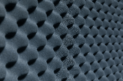
Some acoustic panels have a finely textured surface. This is intended to increase the amount of air absorbed by increasing the surface area. Fine holes and fine fibers also have the effect of diffusing and absorbing sound within a small space.

It is important to note that acoustic panels vary in the frequencies they can easily absorb, depending on the sound absorbing material and the way the layers are made. It is important to clarify the sound you want to absorb with acoustic panels, and then select sound absorption panels that have a large reduction effect.

Other Information on Acoustic Panels

Differences Between Sound Insulation and Soundproofing

In addition to sound absorption, there are other terms, such as sound insulation and soundproofing. Although the terms are similar, they have different meanings.

What Is Sound Insulation?
Sound insulation is the act of blocking air vibrations so that they are not transmitted. To reduce vibration, dense and heavy materials are used. Examples include steel plates, concrete, and plasterboard.

What Is Soundproofing?
Soundproofing is the process of preventing sound from entering from the outside or leaking from the interior to the exterior. Specifically, it is a combination of sound absorption and sound insulation. It does not occupy a specific effect, like sound absorption or sound insulation, but refers to the concept of reducing the intrusion or leakage of sound.

For effective soundproofing, it is important to combine the sound absorption described here with sound insulation using heavy objects.

カテゴリー
category_usa

Vacuum Pads

What Is a Vacuum Pad?

Vacuum Pads

A vacuum pad is a component in a conveying system that absorbs and conveys an object to be conveyed (hereinafter referred to as a “workpiece”).

The vacuum pad is connected to a vacuum generator. With the suction surface of the vacuum pad in contact with the workpiece, the vacuum generator creates a lower pressure (vacuum) in the space between the pad and the workpiece than the ambient air pressure. This causes the vacuum pad to pick up the workpiece for transport. Vacuum pads are used in a variety of fields to improve production efficiency because they require only a vacuum pad and a vacuum generator.

Uses of Vacuum Pads

Vacuum pads are used in various fields because they are available in the configuration of a vacuum pad and a vacuum generator.

For example, they are used to convey relatively heavy metals such as car body pressed steel plates and hot stamping forged steel plates, plate glass, film, plastic, and other plate-like objects, as well as objects with surface roughness such as cardboard boxes and wood.

It can also be used to convey foods such as confectionery and electronic components, such as silicon wafers and cells.

Principle of Vacuum Pads

Vacuum pads are suctioned by creating a vacuum in the space between the pad and the workpiece using a connected vacuum generator. In other words, the principle of the vacuum pad is that suction occurs when the pressure in the space between the pad and the workpiece is lower than the ambient air pressure (usually atmospheric pressure). The suction force of the vacuum pad is directly proportional to the pressure difference between the atmospheric pressure and the pressure inside the pad.

When the vacuum level of the pad, which is controlled by the vacuum generator, is lowered, suction stops when the pad can no longer support the weight of the workpiece. The pad and the workpiece are separated.

There are three types of vacuum generators: ejectors that use the Venturi effect, vacuum pumps that use motor rotation to rotate vanes and suction gas, and vacuum blowers that use impeller rotation to suction surrounding gas.

Types of Vacuum Pads

Vacuum pads are manufactured in various sizes, materials, and shapes in consideration of the operating environment, holding power, and durability to touch various shapes and types of workpieces.

1. Shape

Vacuum pads come in three main shapes: flat, oval, and bellows. The flat type is used for workpieces with flat surfaces.

The ellipsoidal type is used for long, narrow workpieces and is suitable for small areas, such as pipes. The oval shape is flat and has a small volume inside the Vacuum pad, so it can vacuum a workpiece in a short period. The bellows type is used when the height of the workpiece varies due to its bellows shape, and the height needs to be compensated as necessary.

2. Material

Typical materials for vacuum pads are nitrile rubber, silicone rubber, polyurethane, and special high-temperature materials. For example, a silicone rubber vacuum pad is used for food products, which does not affect food products. An oil-resistant, silicone-free vacuum pad is used for automobile bodies.

Vacuum pad material should be matched not only to the material of the workpiece but also to the environment in which it is used. For example, if durability and high-speed transfer are required, a highly durable material that requires less frequent replacement should be used.

How to Select Vacuum Pads

The first step in selecting a vacuum pad is to determine the conditions of use. The main operating conditions include the weight of the workpiece, suction posture, vacuum pressure used, acceleration when lifting the workpiece, acceleration when moving the workpiece, and the coefficient of friction between the workpiece and vacuum pad.

Here, we will use the example of lifting and picking up a workpiece vertically and then moving it horizontally.

  1. First, determine the theoretical holding force of the vacuum pad when the workpiece is lifted vertically and picked up. The theoretical holding force of the vacuum pad when picking up a workpiece vertically is calculated by multiplying the weight of the workpiece by the sum of the gravitational acceleration and the acceleration of lifting the workpiece vertically, and then by the safety factor. The safety factor is a coefficient related to actual use and should be about 1.5 for general workpieces, and 2.0 or higher for workpieces with hazardous or permeable characteristics that require a strong suction effect.
  2. Next, determine the theoretical holding force of the vacuum pad when the workpiece is picked up vertically and then moved horizontally. The theoretical holding force of the vacuum pad when moving the workpiece horizontally is calculated by multiplying the weight of the workpiece by the sum of the acceleration due to gravity and the acceleration when moving the workpiece horizontally divided by the friction coefficient, and then by the safety factor.
  3. Finally, the theoretical holding force of the vacuum pad to be used in the actual equipment is greater than the holding force during pickup or horizontal movement and is used to select the Vacuum pad. In actual equipment, vacuum pads may be used individually or as a set of multiple pads.

The theoretical suction force of an individual vacuum pad is the difference between the atmospheric pressure and the pressure of the pad divided by the atmospheric pressure, multiplied by the suction area and the force due to atmospheric pressure. When using a single pad, select a vacuum pad whose value is greater than the theoretical holding force. When multiple pads are used, the Vacuum pads should be selected so that the value obtained by multiplying the Vacuum pad force of each pad by the number of pads is greater than the theoretical holding force.

Nitrile rubber is often used as the material for Vacuum pads in general applications, but selection should be made according to the Uses of the application and the material of the workpiece, such as using fluorine rubber in clean environments where conductive nitrile rubber or conductive silicon rubber is used in environments where static electricity is not desired.

Other Information on Vacuum Pads

Life of Vacuum Pads

Vacuum pads are made of rubber, so the suction surface wears out with use. Wear conditions vary depending on the frequency of use and vacuum pressure, but severe wear can cause air leakage, reduced suction power, longer suction time, and other problems.

Vacuum pads are usually treated as consumable items and need to be replaced periodically, considering the wear of the suction surface. Although the replacement time varies depending on the operating environment, if the required suction force cannot be obtained due to air leakage caused by wear, it may lead to a major accident, such as a workpiece falling off, so a replacement time should be set well in advance.

For example, the vacuum pressure drop due to leakage at the vacuum pad is measured, and if the pressure drops below a specified value, the pad should be replaced.
カテゴリー
category_usa

Anti-Reflection Coatings

What Is an Anti-Reflection Coating?

An anti-reflection coating is an optical film formed on the surface of a display to reduce surface reflection and reflection of light. A polymer film is layered on top of the base film, and the difference in refractive index between the layers is used to cause interference of light and weaken the reflected light to reduce the reflectance. Some types of anti-reflection coatings have fine particles added to scatter light.

Anti-reflective films are commercially available for home use and can be applied to the surface of TVs, PC monitors, and smartphone displays.

Uses of Anti-Reflection Coatings

Anti-reflection coatings are generally applied to base materials and hard coatings. In addition to suppressing surface reflection, it also inhibits the adhesion of dust and dirt and protects the display.

Anti-reflective films with multiple layers are mainly used for displays on TVs, PC monitors, and smartphones. They are also being considered for use in large equipment such as solar heat collectors and laser equipment for nuclear fusion to prevent energy loss due to surface reflection.

Principle of Anti-Reflection Coatings

Anti-reflection coatings consist of multiple optical layers on a base material. The refractive index at the interface of each layer is different, which causes interference, and this principle is used to reduce the reflectance of specific wavelengths. Multi-layered (multi-coated) films reduce surface reflection and improve the transmittance of displays, etc., making the screen easier to see.

Anti-reflective films can be broadly classified into LR (Low-Reflection) film and AG (Anti-Glare) film. AG films have particles in the hard coat layer to form unevenness on the surface of the film. This surface irregularity scatters incident light, and at the same time, the internal scattering caused by the difference in refractive index between the hard coat layer and the particles can be used to suppress reflection.

カテゴリー
category_usa

Single-Phase Transformer

What Is a Single-Phase Transformer?

A single-phase transformer is a transformer designed for single-phase AC power. It typically consists of one input winding and one or more output windings. Its simple design, involving a primary and a secondary winding, makes it easy to manufacture and maintain, resulting in relatively low cost. Compact and lightweight, Ssingle-phase transformers are suitable for space-constrained locations and mobile equipment.

Applications of Single-Phase Transformers

These transformers are mainly used in commercial and industrial settings for power distribution and control, converting high transmission voltage to lower working voltage. Common applications include:

  • Power distribution in networks.
  • Use in rail vehicles for lighting and air conditioning.

Principle of Single-Phase Transformer

Single-phase transformers operate based on electromagnetic induction. An AC voltage supplied to the primary winding generates a magnetic field, which is transmitted to the secondary windings through an iron core. The secondary winding then produces an induced voltage, depending on its number of turns. The transformation ratio is determined by the turn ratio of the primary to secondary windings.

Types of Single-Phase Transformers

They are classified into:

1. Single-Phase Double-Winding Transformer

Features physically separate primary and secondary windings, insulated with insulating materials and an iron core.

2. Single-Phase Single-Winding Transformer

Uses one winding for both the input and output sides, making it more compact and lighter. Suitable for portable products and space-limited applications.

How to Select a Single-Phase Transformer

Selection criteria include:

1. Voltage

Ensure compatibility with the required input and output voltages.

2. Capacity

Choose a transformer with sufficient power capacity for the load.

3. Load Characteristics

Consider the type of load and operating conditions, especially for loads like motors that require specific transformer capacities.