カテゴリー
category_usa

Cleanroom Clothing

What Is Cleanroom Clothing?

Cleanroom Clothing

Cleanroom clothing is specialized workwear designed to prevent the release of particulates and microorganisms into a cleanroom environment.

Often referred to as dustproof or dust-free clothing, its primary function is to suppress dust emissions. In terms of dust prevention, both the low dust emission of the garment material and its airtightness are crucial factors. Moreover, for worker comfort, the clothing must also offer adequate breathability for long hours of work. Cleanroom clothing is engineered to balance these seemingly contradictory requirements.

Uses of Cleanroom Clothing

Cleanroom clothing is essential in industries where cleanroom environments are mandatory, such as semiconductor, pharmaceutical, food, and other product manufacturing. One of its primary uses is to prevent contamination from airborne bacteria.

Airborne bacteria, which include various microorganisms like bacteria and viruses, are typically present in large numbers in non-clean environments. Since these bacteria can adhere to suspended particles, the risk of contamination increases with the number of airborne particles. Cleanroom clothing plays a dual role: suppressing the generation of airborne particles and preventing the release of human-derived microorganisms, thus reducing the risk of contamination from both particles and airborne bacteria.

Principle of Cleanroom Clothing

Cleanroom clothing is engineered to prevent dust emissions from the wearer. Besides its primary function, it must also be breathable, non-steaming, and facilitate ease of movement. Durability is another important factor, as the clothing must withstand frequent washing and steam sterilization.

The material properties of cleanroom clothing significantly influence its dust emission and filtering capabilities. Common materials include synthetic fibers like polyester filament and aramid fibers. Natural fibers, such as cotton and wool, which are often used in regular clothing, are unsuitable for cleanroom environments due to their tendency to generate dust.

As static electricity can attract particulate matter and cause electric shocks, cleanroom clothing often incorporates anti-static materials or accessories to mitigate static buildup.

Structure of Cleanroom Clothing

Cleanroom clothing typically comes in two main styles: separate upper and lower sections or integrated one-piece suits. For environments requiring high cleanliness levels, one-piece suits with hoods are preferred due to their superior dust control capabilities.

One-piece cleanroom suits have fewer openings and are usually fastened with a zipper at the front. To prevent gaps at the neck, Velcro tapes are often used. Elastic bands at the wrists, ankles, and hoods help eliminate gaps between the garment and the body, further reducing particle emissions.

Types of Cleanroom Clothing

Cleanroom clothing varies depending on the cleanliness level of the environment. Cleanliness is quantified based on the concentration of airborne microparticles and microorganisms. It is generally expressed as the number of particles in a unit volume of air.

The ISO standard 14644-1, based on the JIS, is one of the cleanliness standards. In Japan, the standard used may differ across industries. While the U.S. federal standard has been superseded by the ISO standard, it is still commonly referenced in Japan.

Examples of cleanroom clothing types, classified according to U.S. federal and ISO standards, are as follows:

1. Class 100,000 or Less / ISO Class 8 or Higher

Simple clean wear such as separate upper and lower types or gown types are used, often accompanied by hats instead of hoods. This standard is typically required in environments like automobile parts manufacturing plants.

2. Class 1,000 to 10,000 / ISO Class 6~7

For this class, connected upper and lower garments with either integrated or separate hoods are used. Special clean shoes are also a requirement. This standard applies to food factories and pharmaceutical manufacturing sites.

3. Class 1~100 / ISO Class 3~5

These environments require connected upper and lower garments, sometimes with an additional clean inner layer. Hoods with face shields are common. This standard is necessary for semiconductor factories.

In ISO class 1~2 cleanrooms, human entry is generally restricted, and automated equipment and robots perform the tasks.

Other Information on Cleanroom Clothing

Cleaning Cleanroom Clothing

When cleaning cleanroom clothing, it is necessary to work in an area cleaner than the cleanroom itself. Specialized detergents, washing machines, and pure or ultra-pure water for rinsing are used. Drying is often done using clean air, such as in a dryer equipped with a HEPA filter.

Implementing an IC tag system is beneficial for managing cleanroom clothing inventory and monitoring fiber wear, aiding in determining when garments should be replaced.

カテゴリー
category_usa

Electric Power Cable

What Is Electric Power Cable?

Electric power cable is an electrical conductor used to transmit high current electricity and consists of a conductor surrounded by an insulation layer and covered with a sheath.

They are buried underground in urban and industrial areas to transport electric power, and are also used to supply electric power inside buildings such as residences and commercial facilities. In a broad sense, electric power cable also includes cables used in power outlets.

Uses of Electric Power Cables

Electric power cables are used as high-voltage cables that are buried underground in urban and industrial areas to transport electric power, and as low-voltage cables that supply electric power inside buildings, such as residences and commercial facilities. In the supply of electric power, the transmission of electricity from a power plant to a substation is called transmission, and the distribution of electricity to homes and factories after the voltage is lowered at a substation is called distribution. Wiring is the process of conducting electricity to electric lights and mechanical equipment.

High-voltage cables are used for this transmission of electricity and connect distribution lines or premises wiring owned by electric power cable to high-voltage electrical facilities (cubicles) on the user’s side. They are also used to transmit data to distant locations.

Low-voltage cables, on the other hand, are used for power distribution and wiring. Low-voltage cables often used outdoors to supply electric power cable to residences and commercial facilities are vinyl-type cables with vinyl insulation and sheaths, and rubber-type cables with rubber insulation and sheaths. These vinyl cables are often used for power sources that are used in a fixed position. The sheath is hard and impact-resistant, and is not easily exposed to damage from animals.

Rubber-based cables are characterized by the ability to bend cables while energized. For this reason, they are often used inside cable bearers, curtain cables, etc., where the power source is moving. In addition, their high flexibility makes them easy to penetrate into narrow spaces such as gaps between buildings, making them suitable for use in households and offices in high-rise buildings.

Principle of Electric Power Cables

The basic structure of the electric power cable is a conductor surrounded by an insulating layer and sheathed with a sheath. This conductor is used to transmit, distribute, and route electric power.

The insulating layer ensures that power can be safely supplied while reducing the effects of electrical leakage and the generation of magnetic fields in the surrounding area. In addition, the sheath sheathing protects them from damage.

Types of Electric Power Cables

Electric power cables are broadly divided into two types: low voltage cables that can be used at 600 V DC (750 V AC) or lower, and high voltage cables that can be used at higher voltages. Among high-voltage cables, those exceeding 7,000 V are called special high-voltage cables.

1. Low-Voltage Cables

The structure of low-voltage cables consists of a conductor made of copper or other material surrounded by an insulation layer and sheathed with a sheath. The name and characteristics differ depending on the material of the insulation layer and sheath. For example, a conductor made of copper is surrounded by an insulating layer made of vinyl insulation, which is further covered with a sheath made of vinyl, is called VCT or VCTF.

VCT can be used at 600 V or lower, and VCFT at 300 V or lower. Electric Power Cables with three conductors insulated with vinyl or four conductors, including a grounding wire, are used in most cases, since most of the power sources are three-phase alternating current.

In addition, there is also 1CT with one conductor and 2CT with two conductors, insulated with natural rubber and sheathed with natural rubber. CV cables, which are also used in high-voltage cables, consist of a conductor surrounded by an insulation layer of cross-linked polyethylene and sheathed in vinyl, and are also used as low-voltage cables.

2. High-Voltage Cables

The basic structure of a high-voltage cable is a copper conductor surrounded by an insulating layer of cross-linked polyethylene or the like, which is then sheathed in a vinyl or similar sheath. However, it is characterized by an internal semiconductor layer between the conductor and the insulation layer, and an external semiconductor layer between the insulation layer and the sheath.

The conductor and the insulation layer have different expansion coefficients, which may cause gaps. Gaps can also form if the conductor has a convexity. The internal semiconductor layer prevents partial discharge caused by such gaps. In addition, an external semiconducting layer is placed on top of the insulator to make the electric field uniform, thereby suppressing partial discharge.

Note that electric power cables with a voltage of 6,600 V or higher require a shielding layer between the sheath and the outer semiconducting layer. Electric power cable with a high voltage of 6,600 V or higher must have a shielding layer between the sheath and the outer semiconductor layer. Without shielding, high induced voltages may be applied to peripheral equipment and wiring, and a human body may be electrocuted just by approaching the equipment or wiring. Grounding the shielding allows induced voltages to escape safely to the earth.
ゼータ電位計とは

ゼータ電位計とは、主に液体中の粒子における分散の安定性の指標となるゼータ電位を測定する装置です。低濃度溶液のほか、懸濁液のような粒子が多く配合されている溶液における分散の安定性の評価によく使用されます。

ゼータ電位計の使用用途

ゼータ電位計は、溶液中の粒子における分散の安定性を評価しており、様々な分野で使用されています。

評価対象は、顔料や研磨剤を分散させた工業品、新規機能性材料やナノテクノロジー製品、バイオメディカル製品など溶媒に粒子を分散させた様々な製品です。この結果は、分散の安定性のほか、凝集・沈降、流動性の目安にもなります。

ゼータ電位計の原理

ゼータ電位計はゼータ電位を測定する装置です。そこで、まずはゼータ電位について解説します。

1. ゼータ電位とは

溶液中の粒子のほとんどが、プラスまたはマイナスに帯電しており、その表面は帯電している電荷と反対のイオンの層でおおわれて電気的な中性を保っています。このようなイオンの層は固定イオン層と呼ばれています。その上にはイオン拡散層が形成され、プラスイオンとマイナスイオンが混在する構造です。

このイオン拡散層内のプラスイオンやマイナスイオンの分布は均一ではありません。例えば、固定イオン層がプラスのイオンであると、固定イオン層に近い部分では反対のマイナスのイオンの濃度が高い構造です。固定イオン層から離れるにつれ、マイナスのイオン濃度が低くなり、その分プラスのイオン濃度が増えていきます。

溶液に電界が加わると、粒子が電気泳動します。このとき、粒子にはせんだん力がかかり、イオン拡散層内部で粒子と共に移動する層と、そのまま溶液内の同じ位置に留まる層に分かれます。この境界面は「すべり面」と呼ばれ、このすべり面の電位が「ゼータ電位」です。つまり、ゼータ電位が高いということは、粒子が動きにくいということとなり、分散性が安定していることになります。

2. ゼータ電位で分かること

ゼータ電位が大きければ、粒子間の反発力が強くなり凝集しにくく、安定性が高くなります。一方、ゼロに近い場合には、粒子間が反発しにくいので凝集しやすくなります。すなわち、ゼータ電位は、粒子における分散の安定性の指標です。また、ゼータ電位が高いということは、溶液内で動きづらいということとなり、粒子単体の分散の安定性の目安ともなります。

ゼータ電位計の種類

ゼータ電位計の測定方式で溶液中の粒子分散性を測定するのに適しているのは「電気泳動法」「コロイド振動電流法」です。順番に説明します。

1. 電気泳動法

電気泳動法は、帯電した粒子が移動する速度を利用した測定方法です。粒子が分散している溶液に電圧を印加すると、マイナスの粒子はプラス電極、プラスの粒子はマイナス電極に向かう移動が起こります。このとき、粒子内でのイオン拡散層内にはせんだん力が生じます。

ゼータ電位が大きければ、大きなせんだん力が必要です。すなわち、粒子の移動速度(泳動速度)は遅くなります。したがって、移動速度からゼータ電位を算出し、粒子における分散の安定性を評価できます。

2. コロイド振動電流法

この方法は、コロイドのような高濃度の溶液のゼータ電位を測定するのに好適な方法です。電気泳動法では、粒子が溶液の中をある程度の速さで移動する必要があり、濃度が高い溶液のゼータ電位を測定するには希釈する必要がありました。

しかし、コロイド振動電流法では高濃度の溶液を希釈せずにゼータ電位を測定できます。コロイド振動電流法は、溶液に超音波を照射して溶液を流動ではなく振動させているのが特徴で、この方法であれば濃度が高い溶液も測定可能です。

前述のように、粒子は帯電しており、その周囲には溶媒からなる反対の電荷のイオン層が形成されています。溶液が振動すると、溶媒と粒子では密度が異なるため、帯電した粒子とイオン層の間で分極が生じ、コロイド振動電位(CVP)と呼ばれる電場を発生します。この電場を電位変化として検出し、ゼータ電位として評価するのがコロイド振動電流法です。

ゼータ電位計のその他情報

ゼータ電位計の中で、電気泳動できない50μm以上の粒径の粒子や、繊維および板、フィルターなどのゼータ電位測定には「流動電位法」が用いられています。

流動電位法は、被測定物表面に接した状態で液体を流動させると、溶液の流入側と流出側に電位差が生じることを利用した測定法です。被測定物に接した状態で液体を流すと、被測定物と液体間にイオン拡散層が生じます。そして、イオン拡散層内で液体と共に動く部分と固体表面に留まる部分間にゼータ電位が生じるため、液体の流入側と流出側に電位差が生じるのです。すなわち、流入側と流出側の電位差を測定すれば、ゼータ電位を算出できます。

カテゴリー
category_usa

Through-Beam Sensor

What Is a Through-Beam Sensor?

Through-Beam Sensors

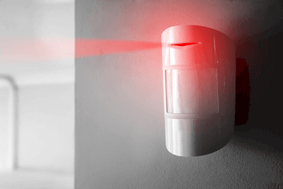
A through-beam sensor is a type of sensor that detects objects by emitting a beam of light.

These sensors utilize visible light, infrared light, and laser light as their light beams. They are capable of detecting the intrusion or movement of people, objects, the location of objects, steps, and more.

Uses of Through-Beam Sensors

Through-beam sensors are widely used in various industries such as factories, residences, parking lots, offices, hospitals, and solar power plants. In the semiconductor and electronics industries, ultra-compact sensors are typically used for detecting bumps and lifts, positioning, detecting the presence or absence of machined holes, component positioning, tip detection, and confirming the arrival of boards.

In hospitals, they are used to signal nurses when a patient leaves the bed. In garages, the sensors can activate patrolling lights or similar systems to notify when someone passes through an entrance or exit. They also play a role in safety, such as reversing and opening doors that are about to close.

For night surveillance of premises, the system triggers a warning alarm when someone enters a specific area. These sensors are also used for detecting intruders in material storage areas and in alarm systems when a vehicle exceeds a specified height limit.

Principle of Through-Beam Sensors

A through-beam sensor comprises a light emitter that emits a light beam, a light receiver, a power supply, and an amplifier. The light beam is either blocked, transmitted, or reflected by an object, causing a change in the amount of light detected by the receiver. This change is then converted into an output signal.

The light sources can be of various colors, including infrared, red, green, blue, and a combination of red, green, and blue. Output circuits may include NPN transistor open collector, PNP transistor open collector, DC 2-wire, NPN transistor universal, relay contact, and other contact outputs. Another common type is the analog output via analog voltage.

Characteristics of Through-Beam Sensors

1. Non-contact Detection

Through-beam sensors enable non-contact detection from a distance, meaning they are not affected by the mounting of the sensor. This allows for long-term, consistent detection.

2. Fast Response

The sensors provide a high-speed response due to their optical beam and fully electronic circuit composition, making them suitable for high-speed production lines.

3. Long Detection Distance

Transmissive sensors are capable of detecting objects from several tens of meters away.

4. Other Advantages

These sensors can detect various colors as differences in light intensity, due to the varying reflection/absorption ratios of specific light wavelengths. They offer high-precision detection, with optics and electronic circuit technology enabling an accuracy of up to 20 µm.

However, a drawback of beam sensors is that dust and dirt accumulation on the lens surface may hinder proper light emission or reception, leading to malfunctions.

Types of Through-Beam Sensors

Through-beam sensors come in various types, depending on their detection method and configuration.

1. Classification by Detection Form

Transmissive, mirror-reflective, and reflective types are common methods for projecting and receiving light. Additionally, there are compact, fiber-type sensors that utilize optical fibers.

Transmissive Type
In this type, the light emitter and receiver are installed separately. Detection occurs when an object interrupts the light beam. Both components require a power supply. This type offers a long detection distance.

Mirror-Reflective Type
Here, the light emitter and receiver are integrated into a single unit, while a separate reflective mirror is used to detect changes in light reflected due to an object or person. This type is less expensive than the transmissive type and can be used over long distances.

Reflective Type
In the reflective type, the light emitter and receiver are integrated. It captures light reflected off an object or person. However, this type has a shorter detection distance and is more susceptible to interference from colors.

2. Classification by Configuration

Through-beam sensors are classified into built-in or separate electronic circuit configurations. Available types include amplifier built-in, power supply built-in, amplifier separate, fiber type, and more. The choice depends on installation space, power supply, and noise immunity considerations.

Amplifier built-in and power supply built-in types can provide non-contact output or relay contact output. In the amplifier separate type, the light-emitting and receiving elements are distinct from the amplifier, allowing for a smaller sensor section. Adding a DC power supply enables non-contact output.

The fiber type connects an optical fiber to the light-emitting and receiving elements in the amplifier body, with the detection end being separate. Light is projected and received through the optical fiber, offering excellent environmental resistance.

カテゴリー
category_usa

Cleanroom Tape

What Is a Cleanroom Tape?

Cleanroom tape, applicable in cleanrooms, comes in various types including double-sided, curing, line, and regular tape. These tapes are manufactured using special methods and materials to minimize dust emission. They often feature antistatic coatings, chemical-resistant films, and sterilization, serving functions beyond just dust control.

Uses of Cleanroom Tapes

In semiconductor and biological clean environments, cleanroom tapes are versatile. They replace regular adhesive tape for tasks like posting notices in cleanrooms. Some are used as curing tapes for construction and repairs, or as line tapes on floors for area demarcation. Traditional cellophane tape, commonly used outside cleanrooms, is unsuitable inside due to dust generation that can compromise product quality. However, cleanroom tapes, being dustproof, are perfectly suitable for use in these environments.

Principles of Cleanroom Tapes

The primary goal of cleanroom tapes is to minimize dust contamination. Unlike regular cellophane tape with a cardboard core prone to dust generation, cleanroom tapes use a plastic core, such as polyethylene, to prevent dust creation. The tape’s base material also comprises dust-resistant plastic films like polyolefins, including polyethylene, polyvinyl chloride, and polypropylene. Produced and packaged in clean environments, cleanroom tapes significantly reduce the risk of dust contamination upon package opening.

カテゴリー
category_usa

Helical Gear

What Is a Helical Gear?

Helical Gears

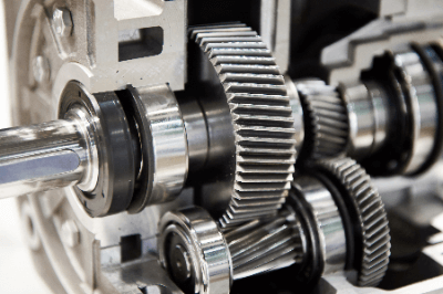
A helical gear is equipped with tooth stripes that are twisted with respect to the shaft. Helical gears are more robust and quieter than spur gears, which have tooth stripes parallel to the shaft due to a higher intermeshing ratio between gears (resulting in a larger meshing area).

These gears are widely used in various transmission devices, reduction gears, and automotive transmissions that require quietness and high transmission efficiency. The helical angle varies depending on the type, and the angles between meshing gears must match.

Uses of Helical Gears

Helical gears are primarily used in transmissions of general passenger cars because of their characteristics of low vibration, smooth meshing, quietness, ride comfort, and the ability to efficiently convert the output from the engine into power.

They are also used in “reduction gears,” which maintain the power source from the motor at a constant speed, and in “transmissions,” which can change the speed at will. These two machines are always attached to anything powered by a motor, so helical gears play a significant role.

Principles of Helical Gears

Helical gears mesh continuously, unlike spur gears, which mesh intermittently. This characteristic makes helical gears less noisy and stronger, even at high speeds.

One drawback of helical gears is the generation of thrust force in the axial direction of the gears due to their structure. 

Thrust Load

The thrust load becomes stronger as the power increases, necessitating a separate bearing to handle the thrust load. Without a bearing, wear and poor rotation will result.

A thrust bearing is required separately from the gear, and space is needed to install the bearing.

To mitigate the thrust load, some helical gears combine right- and left-handed twisted gears (double helical gears), canceling out the thrust load’s effect in the direction it acts, thus eliminating thrust load.

Design of Helical Gears

Helical gears with right-angled teeth have the same meshing as spur gears when viewed from the front of the teeth. Therefore, the same calculation formulas used for spur gears can be applied.

The calculation formula is detailed in the manufacturer’s technical data. It allows you to calculate the dimensions required for gear mounting design, such as the distance between gear centers and the values needed for strength calculations.

Consider the axial force, which is significant for helical gears. Due to their slanted teeth, axial forces occur at the contact surfaces of the teeth, changing direction with rotation and torsion. A combination bearing is often used to support both forward and reverse rotation, with one side fixed axially, and the other providing support. This bearing must handle axial loads, often employing bearings like angular bearings.

Materials such as metal and resin are available, and selecting the material best suited for the application is necessary.

Backlash of Helical Gears

To calculate the amount of backlash in helical gears, use the backlash calculation table specified in the JIS standard. It calculates the gap between teeth by determining tooth thickness reduction and converting it into an angle.

For example, for a JIS Class 5 gear with a tooth perpendicularity module of 2, having 30 and 60 teeth, and a torsion angle of 30°, the frontal module is 2.31, and the pitch circle diameter is 69.3 and 138.6, respectively. These conditions result in a minimum tooth clearance of 130 microns and a maximum clearance of 550 microns. Depending on the application, it may be necessary to adjust the clearance to suit specific requirements.

Be cautious not to make the clearance too small, as it can lead to inadequate lubrication, increased wear, drive torque, and noise. Conversely, if it is too large, it can cause rattling during stopping and vibration during load fluctuations, especially in high-speed operations.


カテゴリー
category_usa

Linear Slide

What Is a Linear Slide?

A linear slide is a mechanical component designed to guide smooth, high-precision linear motion, akin to a smoothly operating drawer. It enables the moving part to glide back and forth with high accuracy, facilitating repetitive movements.

Linear slides vary in size, rigidity, and material, and can be selected from a range of options provided by different manufacturers to suit specific applications and functional requirements. They are increasingly vital in automated manufacturing plants, semiconductor production, and inspection equipment.

Uses of Linear Slides

Linear slides are predominantly used in factory automation, semiconductor manufacturing, and inspection equipment where precision and repetitive linear motion are essential. They are also found in medical equipment, machine tools, and construction projects.

Various types of linear slides are available, including standard types for precise movement, corrosion-resistant models, high-rigidity types, and those designed for easy installation. Selection depends on the specific application and operating environment.

Principles of Linear Slides

A linear slide typically comprises a table (outer frame), a bed (similar to a drawer), and several balls for smooth movement. The outer frame and bed are arranged in a U-shaped assembly, with grooves allowing the balls to roll. The bed moves back and forth within the outer frame, and the balls facilitate this motion by rolling in the grooves.

For stable and smooth operation, many linear slides incorporate retainers to maintain equal spacing between the balls, preventing contact and ensuring smooth movement. Some models also include a feature to prevent retainer shifting, further enhancing stability.

While installation methods vary among manufacturers, all strive to simplify the process. However, it is crucial to follow each manufacturer’s guidelines for installation and use to ensure stable and precise movement.

ゼータ電位計

ゼータ電位計とは

ゼータ電位計とは、主に液体中の粒子における分散の安定性の指標となるゼータ電位を測定する装置です。低濃度溶液のほか、懸濁液のような粒子が多く配合されている溶液における分散の安定性の評価によく使用されます。

ゼータ電位計の使用用途

ゼータ電位計は、溶液中の粒子における分散の安定性を評価しており、様々な分野で使用されています。

評価対象は、顔料や研磨剤を分散させた工業品、新規機能性材料やナノテクノロジー製品、バイオメディカル製品など溶媒に粒子を分散させた様々な製品です。この結果は、分散の安定性のほか、凝集・沈降、流動性の目安にもなります。

ゼータ電位計の原理

ゼータ電位計はゼータ電位を測定する装置です。そこで、まずはゼータ電位について解説します。

1. ゼータ電位とは

溶液中の粒子のほとんどが、プラスまたはマイナスに帯電しており、その表面は帯電している電荷と反対のイオンの層でおおわれて電気的な中性を保っています。このようなイオンの層は固定イオン層と呼ばれています。その上にはイオン拡散層が形成され、プラスイオンとマイナスイオンが混在する構造です。

このイオン拡散層内のプラスイオンやマイナスイオンの分布は均一ではありません。例えば、固定イオン層がプラスのイオンであると、固定イオン層に近い部分では反対のマイナスのイオンの濃度が高い構造です。固定イオン層から離れるにつれ、マイナスのイオン濃度が低くなり、その分プラスのイオン濃度が増えていきます。

溶液に電界が加わると、粒子が電気泳動します。このとき、粒子にはせんだん力がかかり、イオン拡散層内部で粒子と共に移動する層と、そのまま溶液内の同じ位置に留まる層に分かれます。この境界面は「すべり面」と呼ばれ、このすべり面の電位が「ゼータ電位」です。つまり、ゼータ電位が高いということは、粒子が動きにくいということとなり、分散性が安定していることになります。

2. ゼータ電位で分かること

ゼータ電位が大きければ、粒子間の反発力が強くなり凝集しにくく、安定性が高くなります。一方、ゼロに近い場合には、粒子間が反発しにくいので凝集しやすくなります。すなわち、ゼータ電位は、粒子における分散の安定性の指標です。また、ゼータ電位が高いということは、溶液内で動きづらいということとなり、粒子単体の分散の安定性の目安ともなります。

ゼータ電位計の種類

ゼータ電位計の測定方式で溶液中の粒子分散性を測定するのに適しているのは「電気泳動法」「コロイド振動電流法」です。順番に説明します。

1. 電気泳動法

電気泳動法は、帯電した粒子が移動する速度を利用した測定方法です。粒子が分散している溶液に電圧を印加すると、マイナスの粒子はプラス電極、プラスの粒子はマイナス電極に向かう移動が起こります。このとき、粒子内でのイオン拡散層内にはせんだん力が生じます。

ゼータ電位が大きければ、大きなせんだん力が必要です。すなわち、粒子の移動速度(泳動速度)は遅くなります。したがって、移動速度からゼータ電位を算出し、粒子における分散の安定性を評価できます。

2. コロイド振動電流法

この方法は、コロイドのような高濃度の溶液のゼータ電位を測定するのに好適な方法です。電気泳動法では、粒子が溶液の中をある程度の速さで移動する必要があり、濃度が高い溶液のゼータ電位を測定するには希釈する必要がありました。

しかし、コロイド振動電流法では高濃度の溶液を希釈せずにゼータ電位を測定できます。コロイド振動電流法は、溶液に超音波を照射して溶液を流動ではなく振動させているのが特徴で、この方法であれば濃度が高い溶液も測定可能です。

前述のように、粒子は帯電しており、その周囲には溶媒からなる反対の電荷のイオン層が形成されています。溶液が振動すると、溶媒と粒子では密度が異なるため、帯電した粒子とイオン層の間で分極が生じ、コロイド振動電位(CVP)と呼ばれる電場を発生します。この電場を電位変化として検出し、ゼータ電位として評価するのがコロイド振動電流法です。

ゼータ電位計のその他情報

ゼータ電位計の中で、電気泳動できない50μm以上の粒径の粒子や、繊維および板、フィルターなどのゼータ電位測定には「流動電位法」が用いられています。

流動電位法は、被測定物表面に接した状態で液体を流動させると、溶液の流入側と流出側に電位差が生じることを利用した測定法です。被測定物に接した状態で液体を流すと、被測定物と液体間にイオン拡散層が生じます。そして、イオン拡散層内で液体と共に動く部分と固体表面に留まる部分間にゼータ電位が生じるため、液体の流入側と流出側に電位差が生じるのです。すなわち、流入側と流出側の電位差を測定すれば、ゼータ電位を算出できます。

Microwave Heating System

What Is a Microwave Heating System?

A microwave heating system is a system that heats dielectric materials using electromagnetic waves with a wavelength of about micrometers.

In other heating methods (using radiation from hot air or electric heating), heat is gradually conducted from the surface of the object and heated, which takes a certain amount of time.

Microwave heating, however, reacts directly with the molecules inside the material, thus raising the internal temperature in a shorter time. Because microwaves can be irradiated almost uniformly to the target, even inside and outside of the material can be heated uniformly. Since the heating efficiency varies depending on the dielectric loss of the target, the material can also be selectively heated according to the loss factor.

Uses for Microwave Heating System

Although microwave heating systems are best known for their use in microwave ovens, they are also applied industrially for food-related applications.

Specifically, they are used for cooking, sterilization, and drying of food products. For example, when microwave heating system is used in the process of heating chicken, the heating time can be reduced by half compared to the conventional method, and even partial darkening of the bones can be prevented.

Microwave heating is also used to dry wood, printed matter, textiles, and paper, and in the medical field, thermal therapy is being used to treat cancer.

Principle of Microwave Heating System

Electromagnetic waves such as microwaves act on materials by periodically changing the intensity of the electric field.

Unlike conductors such as metals, molecules of insulators (dielectrics) such as water have their own polarity, so they react with the electric field of electromagnetic waves, causing a bias in the distribution of positive and negative charges among the molecules inside the dielectric.

As the frequency of electromagnetic waves increases, the molecules that make up the dielectric rotate and vibrate violently and collide with each other, but a higher frequency does not necessarily mean that heating is easier. If the frequency is too high, the molecules inside the dielectric cannot respond.

In the case of water, it reacts well with electromagnetic waves in the microwave region (infrared rays). The energy generated by the reaction (internal energy) is converted into heat, which heats the dielectric. Microwave heating systems are equipped with electron tubes called magnetrons to generate microwaves. The microwaves emitted from this tube are guided into the heating oven, where they heat the object.

リニアステージ

監修:CKD日機電装株式会社

リニアステージとは

リニアステージとは、リニアサーボモータを搭載したテーブル機構です。位置検出にリニアエンコーダを使用したフルクローズ制御を行うことで、精密な位置決めと動作性能を可能とする機電一体のダイレクトドライブシステムとなります。

直交する2軸を組合せたXY軸や垂直方向のZ軸、回転テーブルのθ軸など、複数の軸を組み合わせる事でXYステージ、XYZステージ、XYZθステージなどの多軸化や用途に合わせた軸構成が可能です。
リニアサーボモータはダイレクトドライブモータですので、中間機構を介在せずに駆動出来ます。機械性能の向上、省スペース化、環境性の向上、メンテナンスの軽減、長距離駆動が可能です。

リニアステージはその特性を生かし、精密位置決め用途や搬送用途に使用されます。
精密位置決め用途では、ボールネジ、ラック・ピニオン、ベルト等の搬送機構に比べ、速度安定性に優れた高精度位置決めが可能です。

リニアステージの使用用途

リニアステージは、位置決め精度や速度安定性能が求められる精密加工装置や検査装置に使用されています。

例えば以下の用途があります。
レーザー加工機半導体露光装置プローバーなど高い位置決め精度が求められる装置
・コーター装置、画像検査装置など速度安定性能が求められる装置
・振動試験機、加振機、シミュレータなど相反動作で振動を抑えた高加速度の実現が求められる装置

その他の用途として、ロングストローク搬送装置、高速ハンドラ装置、高速プレス機の材料送り出し機構部などの搬送用途があります。

リニアステージの原理

リニアステージの構造は、駆動源にリニアサーボモータ、位置を検出するリニアエンコーダ、可動部の案内機構である直線軸受で構成され、モータを制御するサーボドライバによって指令通りの動作をします。

一般的にリニアステージは、固定子にマグネットユニット、可動子にコイルユニットを配置します。
コイルに電流を流すことで地場が発生し、電磁誘導の法則によりマグネットユニットに沿ってコイルユニットに推進力が生じて、可動子がストロークします。
また、リニアステージには、位置を検出するリニアエンコーダが必要となり、高分解能エンコーダによる精密位置検出とサーボドライバによるフルクローズ制御を用いることで、高い精度と速度安定性を実現します。

リニアステージの高精度化には、各構成要素の設置条件や性能が重要となります。
リニアガイドなどと呼ばれる直線軸受の走り精度や設置面の精度が、リニアステージの直進性に大きく影響します。
リニアエンコーダの設置位置はアッベの原理を考慮して、ワークポイントに近い位置に設置することが望まれます。
また、リニアサーボモータは自身が発熱源となります。ダイレクトドライブ機構であるが故にワークやリニアエンコーダへ熱が伝達しやすく、熱膨張によって精度が変化してしまうことがあります。
よって、放熱性能の向上や冷却機構を追加するなどの対策が肝要です。

【リニアステージの構成要素】

本記事はリニアステージを製造・販売するCKD日機電装株式会社様に監修を頂きました。

CKD日機電装株式会社の会社概要はこちら