What Is a Helical Gear?
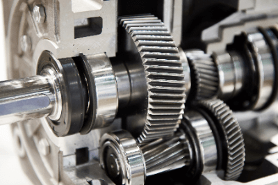
A helical gear is equipped with tooth stripes that are twisted with respect to the shaft. Helical gears are more robust and quieter than spur gears, which have tooth stripes parallel to the shaft due to a higher intermeshing ratio between gears (resulting in a larger meshing area).
These gears are widely used in various transmission devices, reduction gears, and automotive transmissions that require quietness and high transmission efficiency. The helical angle varies depending on the type, and the angles between meshing gears must match.
Uses of Helical Gears
Helical gears are primarily used in transmissions of general passenger cars because of their characteristics of low vibration, smooth meshing, quietness, ride comfort, and the ability to efficiently convert the output from the engine into power.
They are also used in “reduction gears,” which maintain the power source from the motor at a constant speed, and in “transmissions,” which can change the speed at will. These two machines are always attached to anything powered by a motor, so helical gears play a significant role.
Principles of Helical Gears
Helical gears mesh continuously, unlike spur gears, which mesh intermittently. This characteristic makes helical gears less noisy and stronger, even at high speeds.
One drawback of helical gears is the generation of thrust force in the axial direction of the gears due to their structure.
Thrust Load
The thrust load becomes stronger as the power increases, necessitating a separate bearing to handle the thrust load. Without a bearing, wear and poor rotation will result.
A thrust bearing is required separately from the gear, and space is needed to install the bearing.
To mitigate the thrust load, some helical gears combine right- and left-handed twisted gears (double helical gears), canceling out the thrust load’s effect in the direction it acts, thus eliminating thrust load.
Design of Helical Gears
Helical gears with right-angled teeth have the same meshing as spur gears when viewed from the front of the teeth. Therefore, the same calculation formulas used for spur gears can be applied.
The calculation formula is detailed in the manufacturer’s technical data. It allows you to calculate the dimensions required for gear mounting design, such as the distance between gear centers and the values needed for strength calculations.
Consider the axial force, which is significant for helical gears. Due to their slanted teeth, axial forces occur at the contact surfaces of the teeth, changing direction with rotation and torsion. A combination bearing is often used to support both forward and reverse rotation, with one side fixed axially, and the other providing support. This bearing must handle axial loads, often employing bearings like angular bearings.
Materials such as metal and resin are available, and selecting the material best suited for the application is necessary.
Backlash of Helical Gears
To calculate the amount of backlash in helical gears, use the backlash calculation table specified in the JIS standard. It calculates the gap between teeth by determining tooth thickness reduction and converting it into an angle.
For example, for a JIS Class 5 gear with a tooth perpendicularity module of 2, having 30 and 60 teeth, and a torsion angle of 30°, the frontal module is 2.31, and the pitch circle diameter is 69.3 and 138.6, respectively. These conditions result in a minimum tooth clearance of 130 microns and a maximum clearance of 550 microns. Depending on the application, it may be necessary to adjust the clearance to suit specific requirements.
Be cautious not to make the clearance too small, as it can lead to inadequate lubrication, increased wear, drive torque, and noise. Conversely, if it is too large, it can cause rattling during stopping and vibration during load fluctuations, especially in high-speed operations.