カテゴリー
category_usa

Washer Head Screw

What Is a Washer Head Screw?

Washer Head Screws

A washer head screw is a screw with an integrated washer in its design. These screws are designed to securely join parts together, providing a strong bond. The incorporation of washers improves the stability of the joint, helping to withstand vibration and shock, and reducing the likelihood of loosening.

Washer head screws are also convenient for assembly work, as the built-in washer part simplifies the process and enhances work efficiency by reducing the need for re-tightening.

Applications of Washer Head Screws

Washer head screws are used in various industries and applications:

1. Automotive

In automotive assembly and repair, these screws are used in engine assembly, chassis, body panel assembly, and interior panel installation, providing stable joints capable of withstanding vibrations and impacts.

2. Electronic Equipment

Used in assembling circuit boards and enclosures in electronic equipment, these screws help in securely joining enclosure parts, preventing shifting or loosening due to vibration and shock.

3. Furniture Manufacturing

In the furniture manufacturing industry, washer head screws are used to attach metal parts to wood, ensuring stability and durability. They are also user-friendly for furniture that requires assembly by the consumer.

Principle of Washer Head Screws

These screws are typically made by first manufacturing the screw head and then pressing the washer through the head side, making the washer a permanent part of the screw. The manufacturing process usually leaves an unthreaded area near the base of the washer, known as the imperfectly threaded area, which must be considered when fixing thin plates.

How to Select Washer Head Screws

When choosing washer head screws, consider the following:
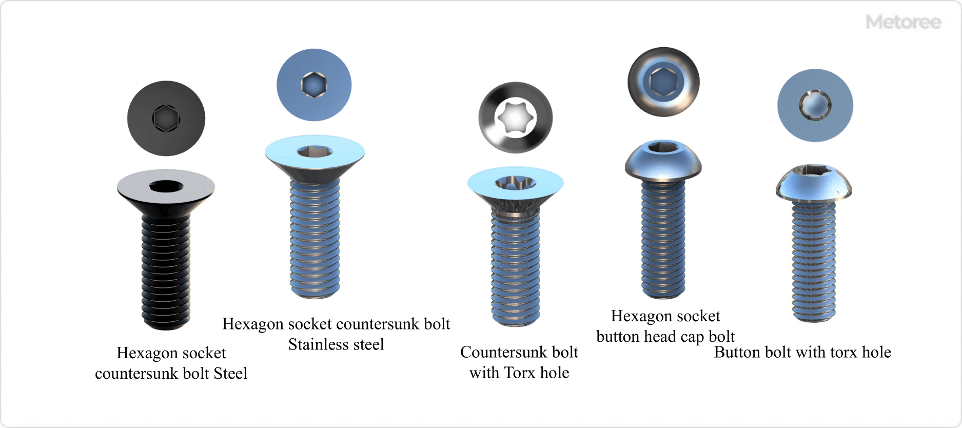
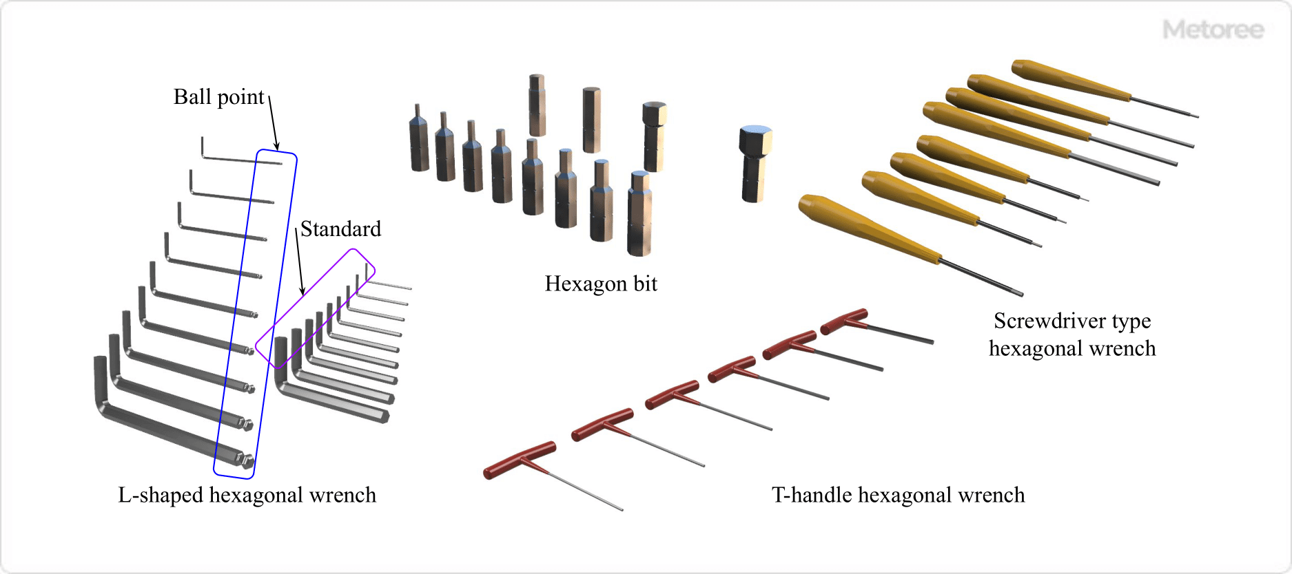
1. Head Shape

Select the head shape based on the tool used and the space available. Hexagonal heads are useful in tight spaces, while aesthetically pleasing head shapes are preferable for visible areas.

2. Material

Choose materials based on the operating environment and application. Options include stainless steel for corrosion resistance and carbon steel for strength.

3. Length

Select the correct length to ensure a secure connection without causing internal collisions or failing to bond adequately.

4. Screw Pitch

Choose the right thread pitch, which is the distance a screw travels in one turn, to ensure the effective joining of parts. Pitch is typically expressed in metric or inch measurements.

カテゴリー
category_usa

Optical Connectors

What Is an Optical Connector?

Optical Connectors

An optical connector is designed for connecting fiber-optic lines, facilitating the complete connection of optical fiber cables for efficient optical signal transmission. These connectors allow for easy and reliable linkage of optical lines, simplifying installation and maintenance. Precision engineering ensures minimal optical loss, enhancing signal transmission and extending reach.

However, due to their precision, the contact area with the optical fiber must be clean to maintain signal quality and efficiency. Handling in clean environments and using protective caps is crucial.

Uses of Optical Connectors

Optical connectors are widely used across various industries:

  • Telecommunications: In constructing fiber-optic networks for long-distance communication and high-speed data transmission.
  • Data Centers: Connecting servers and storage systems for high bandwidth and signal quality.
  • Other Applications: Including television broadcasting, medical and industrial equipment, and in the aerospace and defense sectors, where high-speed and stable data transmission are crucial.

Principle of Optical Connectors

An optical connector typically comprises a housing and a ferrule holding the fiber end. It operates on the principle of direct end-to-end butting, requiring high-precision alignment to minimize connection loss. Connectors are typically mated using an optical adapter with a split sleeve for alignment. The connector ends are often PC-polished (spherical polishing) to avoid air layer formation and achieve minimal loss connections.

Types of Optical Connectors

Common types of optical connectors include:

  • SC (Subscriber Connector): Features a cylindrical ferrule with a push-pull latching mechanism, commonly used for single-mode fiber optic cables.
  • LC (Luciferous Connector): Small form factor connectors, suitable for high-density cabling environments and used for both single-mode and multimode fibers.
  • ST (Straight Tube): Utilizes a bayonet coupling mechanism, ideal for multimode fibers, often used in network equipment and data communication applications.
  • FC (Fiber Connector): Features a threaded coupling mechanism, offering durability and high signal quality, typically used in industrial and defense applications for single-mode fibers.

防曇試験機

防曇試験機とは

防曇試験機とは、透明な材料の曇りの度合を測る試験機です。防曇試験機は、視覚確保が重要な特性であるガラスやレンズなどの製品の曇り度合いを評価します。

防曇試験機の使用用途

防曇試験機は、透明な材質における曇りの度合の測定に使用されます。ガラスやレンズなどの曇り度合いの測定が主な使用用途です。

具体的な使用用途としては、視認性による安全性能が重要な製品の評価が挙げられ、自動車や建材のガラスやバイクのヘルメットのフェイス部分などの評価があります。また、防曇試験機は、スーパーやコンビニの冷蔵ケースのガラスや弁当のふた、食品の包装フィルムなど商品価値を付与するために視認性が必要な製品の評価にも使用されています。さらには、胃カメラのレンズなどの医療機器のレンズの評価も防曇試験機の重要な使用用途です。

さらには、撥水処理した被測定物の防曇性能の評価にも使用されています。

防曇試験機の原理

ここでは、「防曇性能」を「ヘイズ値」を利用して評価する防曇試験機(ヘイズメーター)と、「画像圧縮解析」を利用して評価する防曇試験機の原理について述べます。

1.「曇る」現象について

まずは、「防曇試験」で測定する「曇る」現象について解説します。ガラスやレンズが曇る原因は「結露」です。結露は、空気中の水蒸気が冷却されると凝縮し、固体の表面(内部)に水滴として付着することにより生じます。

この水滴によりガラスやレンズを透過した光が散乱し、ガラスやレンズを通して見た像がぼやけて見える現象が「曇る」現象です。

2.「ヘイズ値」を利用した防曇試験機について

「ヘイズ値」とは、被測定物における全透過光中の散乱成分の割合のことです。

具体的には、まず、被測定物であるガラスやレンズといった透明な物体に光を透過させ、透過光の平行成分と散乱成分の全てを含んだ全光線透過率を測定します。次に、被測定物の透過光中のうち平行成分を除去して散乱成分のみを測定します。ヘイズ値は、この全光線透過率中の散乱成分の割合、ヘイズ値(%) = 散乱成分 / 全光線透過率 × 100 で求められる値です。

前項で述べたように「曇り」があると、透過光が散乱するため、曇りが少なく透明度の高い被測定物におけるヘイズ値は0に近くなり、「曇り」の度合いが増すにつれ、ヘイズ値が大きくなります。すなわち、「ヘイズ値」を用いた防曇試験機(ヘイズメーター)では、散乱成分の割合を評価することで定量的に「防曇性能」を評価可能です。

なお、ヘイズメーターのおおまかな構成は、光源、積分球、受光器、トラップなどで、光源から被測定物に光を照射し、透過光を積分球により集光して受光器で受光しています。トラップは平行成分を除去するための部材です。

3.「画像圧縮解析」を利用した防曇試験機について

次に、「画像圧縮解析」を利用した防曇試験機について説明します。この防曇試験機では、所定の物体を被測定物であるガラスやレンズを通して撮影し、画像として取得しています。ガラスやレンズが曇っていない状態での画像とガラスやレンズが曇っている状態での画像を比較することにより「曇り」度合いの評価が可能です。

まずは、ガラスやレンズが曇っていない状態で所定の物体を撮影し、第1の画像を取得します。この画像は、像がくっきりとしている画像です。次に、ガラスやレンズが曇った状態で所定の物体を撮影すると、像がぼやけた第2の画像が得られます。

輪郭がくっきりしている第1の画像を圧縮すると、輪郭部分のピクセルパターンが多くファイル容量が大きくなります。一方、輪郭がぼやけている第2の画像を圧縮すると、輪郭部分のピクセルが幾つかまとめて処理されるため、ファイル容量は第1の画像より小さな値です。

つまり、この防曇試験機では、この圧縮後のファイル容量を比較することで「曇り」度合いを評価しています。「曇り」度合いが高いほど圧縮後のファイル容量が小さくなるため、「防曇性能」を定量的な評価できます。さらに、この防曇試験機では画像を用いて評価していることから、目で見た状態に限りなく近い条件で防曇性能を評価できるのが大きなメリットです。

防曇試験機のその他情報

防曇試験としては、上記の「ヘイズ値」を利用した「画像圧縮解析」を利用した方式以外に、従前よりおこなわれていた「目視による官能評価」「接触角計による評価」があります。順番に解説します。

1. 目視による官能評価

この方法では、「目視」により評価しています。最も多く使用されている方法ですが、定量的に評価をおこなうことが難しく、検査者によるばらつきが生じる可能性があることがデメリットです。

2.接触角計による評価

この方法では、曇りの原因となる結露とガラスやレンズなどの被測定物との接触角を測定して曇りの度合いを評価しています。ただし、近年、この接触角と結露に相関性が見られないことが分かってきています。

受託測定

受託測定とは

受託測定とは、顧客が自社製品などの様々な特性を評価するための各種測定を外部に委託した測定の事です。自社にて最新測定器や最新技術を保持することなく、専門家に依頼できることから利用する企業が増えています。

受託測定の使用用途

受託測定の分野は多岐にわたります。例えば、誘電率や透磁率といった電気的特性の測定や、物品の厚さ測定、CTなどによる外形の測定、電子顕微鏡などによる表面形状の測定などです。

中でも、近年、表面化学の分野における測定の需要が大きく伸びています。表面化学は、実に様々な分野で応用されており、例えば固体表面の濡れ性や曇り度合いの測定や、粒子を含んだ液体の分散性の評価などに使用されています。

具体的には、固体表面であれば、ガラスやレンズの曇り具合や、撥水加工の水のはじき具合の測定、粒子の分散性であればインクやペーストのほか、バイオ製剤の粒子の分散性などを測定しています。

受託測定の原理

ここでは、撥水・防水剤を開発している場合を想定して解説します。

撥水・防水剤をスプレーなどとして製品化するのであれば、溶液中における成分の分散の度合いや安定性を評価する必要があります。また、撥水・防水剤を用いて加工した被加工物の水に対する濡れ角度や泥などに対する濡れ角度の評価も撥水・防水性を評価する上で必要です。さらに、撥水・防水加工をガラスやプラスチックシールドに施した場合の防曇性なども評価したい項目です。

これらの性能は表面化学を得意とする企業に受託測定を依頼することが好ましく、該当する企業を探す必要があります。測定を専門にしている企業であるため、ノウハウも多く持っており、顧客が考えている方法以外の提案も期待できます。

また、データの加工方法も顧客が見たい結果に合わせて加工が可能です。受託測定をおこなう企業では、顧客が自社にて評価するよりも、幅広い視野で顧客のニーズ合わせた測定方法を提案し、かつ結果を顧客が知りたいポイントに合わせた結果の加工が可能です。

受託測定のその他情報

1. そのほかの試験

表面化学の分野の受託測定を得意としている企業では、表面張力に関する測定や摩擦に関する測定、粘着物の粘着性を測定する引張試験なども請け負っています。

2.JIS規格など

この記事で挙げた表面化学系の試験に関するJIS規格をお知らせします。防曇試験のJIS規格は、日本工業規格JIS S 7027-1993に規定されるように目視による試験です。また、コロイド分散系−ゼータ電位の光学的測定法は、日本工業規格JIS Z 8836:2017 (ISO 13099-2:2012) に規定されています。さらに、日本工業規格 JIS R 3257 : 1999により基板ガラス表面のぬれ性試験方法が決まっています。引張試験のJIS規格は、日本工業規格JIS K 7161やJIS K 7113などです。

なお、受託測定を請け負う企業では、JIS規格の他、ISO規格やEU規格に対応する測定をおこなっている企業が多くあります。

カテゴリー
category_usa

Ceramic Screw

What Is a Ceramic Screw?

Ceramic screws, manufactured from ceramic materials, offer unique properties suitable for various applications. Their resistance to high temperatures and chemicals makes them ideal in environments like industrial furnaces where such conditions are prevalent. Additionally, their electrical insulation properties are beneficial in electronic and electrical circuits, preventing interference with adjacent components.

However, ceramics are more brittle than common metals and are vulnerable to shock and vibration, leading to a higher risk of breakage under excessive loads or impacts. They are often more costly than metal materials, necessitating careful consideration of cost constraints.

Applications of Ceramic Screws

Ceramic screws are used in specific environments due to their unique properties:

1. High-Temperature Environments

With excellent heat resistance, ceramic screws are used in casting and welding processes, and in areas where high temperatures surpass the endurance of metal screws.

2. Chemical Industry

In the chemical industry, ceramic screws are favored for their resistance to corrosive substances, often used in acidic and alkaline environments.

3. Electronics

As insulators, ceramic screws are advantageous in securing circuit boards in electronic equipment and high-voltage areas requiring insulation. They are also suitable for high-frequency and microwave signal transmission.

4. Medical Devices

Due to their high biocompatibility, ceramic screws are used in medical devices and dental tools, such as artificial joints and dental implants, playing a crucial role as components introduced into the human body.

Principle of Ceramic Screws

Ceramic screws are available in various shapes like hexagon socket head cap screws, pan head screws, flat head screws, and mounting screws, allowing selection based on application needs. They are produced using standard ceramic processing methods such as cutting and forming. Forming methods include press forming and extrusion while cutting involves shaping ceramics using machine tools such as lathes, machining centers, and milling machines.

Post-formation, parts undergo sintering at high temperatures to bond ceramic particles and strengthen the structure. The sintering process varies in temperature and time based on the material. Ceramic screws may also receive surface coatings or protective layers to enhance wear and corrosion resistance.

How to Select Ceramic Screws

Consider the following when choosing ceramic screws:

1. Screw Shape

Select the screw shape based on installation efficiency and fastening needs. Button head or flat head screws are suitable for applications requiring close adhesion, while truss head screws distribute pulling force more evenly.

2. Dimensions and Screw Diameter

Choose screw dimensions and diameters to match the application and ensure secure fastening. Metric screw diameters, typically prefixed with ‘M’, are commonly used.

3. Types of Ceramics

Various types of ceramics offer different properties. Select ceramics with high heat resistance for high-temperature environments and those with excellent corrosion resistance for chemical environments. Choose the ceramic type that best suits the application’s requirements.

カテゴリー
category_usa

Cap Screw

What Is a Cap Screw?

A cap screw is a bolt with a cylindrical or countersunk bolt head and a hexagonal hole drilled in its upper end face.

Generally, “cap screw,” “socket screw,” and “hexagon socket head cap screw” are also used as synonyms.

The standards for cap screws are as follows:

  • ASME/ANSI B18.3 Hexagon Socket Head Screws

Usage of Cap Screws

Figure 1. Example of cap bolt use (1)

Figure 1. Example of cap bolt use (1)

Cap screws are primarily used to mount and secure components on small machines and equipment where space is limited for installation.

To tighten cap screws, use a tightening tool such as a hexagonal wrench (Allen wrench) appropriate for the size of cap screw. Compared to a wrench or a monkey wrench, a hexagonal wrench has the advantage of applying a stronger tightening force with less force and requiring less work space around the bolt when tightening.

Figure 2. Example of cap bolt use (2)

Figure 2. Example of cap bolt use (2)

However, since hexagonal wrenches are available in millimeter and inch sizes, care must be taken in selecting a hexagonal wrench. Also, by drilling a counterbored hole slightly larger than the diameter of the cylindrical head of the cap screw and slightly deeper than the height of the head, the cap screw can be installed without the head protruding.

Counterbore holes are drilled in the mounting area so that the bolt head is hidden. The interference between the bolt head and other parts is avoided, resulting in a clean and neat appearance.

Principle of Cap Screws

Cap screws are fastened by means of a screw (in this case, “screw” refers only to the screw shape), the same as an ordinary hexagonal bolt. Cap screws are often used to fasten directly onto a tapped female thread without using a nut.

Instead of inserting a wrench into the bolt head like a hexagonal bolt, a wrench with a hexagonal cross section is inserted into the hexagonal hole and tightened. For this reason, it is necessary to secure a space between the bolt heads and other parts. However, the cap screw tightening tool does not require space outside the bolt head because of the hexagonal wrench, allowing the cap screw to be placed close together.

Used when high tightening force and high strength are required. It is important to select the appropriate material and strength classification for the location and application.

Types of Cap Screws

Figure 3. Type and shape of cap bolts (1)

Figure 3. Type and shape of cap bolts (1)

Cap screws are classified by the shape of the cap screw head and the shape of the hole for the fastening tool.

Types by cap screw head shape are as follows:

  • Hexagon socket head cap bolt
  • Hexagon socket low head bolts
  • Hexagon socket countersunk bolt
  • Hexagon socket button bolt

Figure 4. Type and shape of cap bolts (2)

Figure 4. Type and shape of cap bolts (2)

In addition to the hexagonal hole, there is a hexagonal star-shaped groove Torx hole.

Other Information on Cap Screws

Tightening Tools for Cap Screws

Figure 5. Type and shape of cap bolt tightening tool

Figure 5. Type and shape of cap bolt tightening tool

The most commonly used tools for tightening cap screws are L-shaped Allen wrenches (hexagonal bar wrenches), T-handle Allen wrenches, screwdriver Allen wrenches, and hexagonal bits. Hexagonal wrenches and hexagonal bits have either a “flat” or “ball point” tip shape on the side where the cap screw is inserted.

The shape of the tip of the ballpoint is R-processed at the corner so that the hexagonal wrench can be tightened even when the hexagonal wrench is at an angle.

カテゴリー
category_usa

Tool Balancer

What Is a Tool Balancer?

A tool balancer is a device that suspends tools, such as hand tools, via a wire or air hose in areas where manual labor is performed.

When a suspended tool is used, the wire or air hose extends to the length pulled and retracts to its original length when released. This feature allows the tool to be kept out of the way when not in use, maintaining a tidy workspace and improving work efficiency. Tool balancers are also beneficial for suspending heavy tools that are difficult to hold for extended periods.

Uses of Tool Balancers

Tool balancers are utilized in various workplaces to suspend tools for manual tasks. Common settings include automotive assembly lines, machine tool setup areas, and electrical product assembly lines.

Tools typically suspended include hand tools such as wrenches, electric screwdrivers, air impact wrenches, and air guns. Using multiple tool balancers allows for the selection and use of the necessary tools as needed.

Principles of Tool Balancers

Tool balancers are designed to exert a force on the wire that slightly exceeds the weight of the tool, ensuring smooth extension and retraction. The wire extends when a tool is pulled and retracts to its original length upon release.

The primary mechanisms for generating rewinding force are springs and electric motors. In spring-operated balancers, the winding force increases with the length of wire unwound. To counteract this and maintain a constant pulling force, the winding section is designed with a tapered helix shape, allowing the radius to increase as the spring’s elastic force grows. Electric motor types adjust the take-up torque based on the weight of the suspended tool.

For suspending air tools, an air hose is used in place of wire in tool balancers. The hose is designed to withstand the force of suspending the tool while also providing an internal air channel to supply air to the tool.

カテゴリー
category_usa

Combination Air Filter/Regulator/Lubricator (FRL)

What Is a Combination Air Filter/Regulator/Lubricator (FRL)?f

An FRL combination refers to three pieces of air equipment installed in the middle section of a pneumatic circuit. The components are a filter, a regulator, and a lubricator. It is also called a “three-piece air set” and has been used for a long time.

They are mainly installed in pneumatic circuits to supply air normally. The capacity and other factors are considered and installed according to the operating pressure and the amount of air used. During maintenance, it is necessary to remove water from the filter and replenish the lubricator drive oil.

Uses of FRLs

Rarely an air combination unit is not installed where pneumatic equipment is installed.

They are installed in front of the pneumatic devices that drive the solenoid valves, air cylinders, etc., and are used to protect these devices. Filters are installed to remove moisture, regulators to optimize pneumatic pressure, and lubricators to lubricate drive units. Many oil-free pneumatic systems have been available in recent years so the lubricator may be omitted.

Principle of FRLs

An air combination is divided into three parts, the filter, regulator, and lubricator, each of which has its role.

The filter is initially used to remove moisture from compressed air. Compressed air used in pneumatic circuits contains a lot of moisture. If compressed air is introduced into the drive unit in this state, the moisture will corrode the drive unit. In addition, the drive unit is coated with grease to ensure smooth operation, and the moisture may wash away the grease. Therefore, a filter is used to remove the moisture first.

Next, a regulator maintains the optimum pressure for the equipment. The drive unit has a fixed allowable air pressure, and if the air pressure exceeds the upper limit, the drive unit may fail. The regulator reduces the pressure to prevent excessive pressure from being applied to the drive unit.

Finally, although the drive unit is coated with grease in advance, air pressure and humidity gradually deplete the grease. To supplement this grease, drive oil is supplied by a lubricator.

Thus, the FRL combination is a component that preserves the air drive system through three elements.

カテゴリー
category_usa

Selector Switch

What Is a Selector Switch?

Selector Switches

A selector switch is a switch that selects from multiple options. Typically featuring a disk-shaped or square knob, it can be rotated to choose different options. These switches are simple to operate, allowing quick selection by turning the knob. This is especially useful when multiple choices or modes are available.

Selector switches are mechanically operated, ensuring reliable and trustworthy operation. However, they are limited to selecting from a predefined set of options and may not accommodate new choices or settings without modification.

Uses of Selector Switches

Selector switches have various applications, including:

1. Audio Equipment

In audio equipment, selector switches are used to choose different input sources and control volume levels, facilitating user preference for music or content and volume adjustments. They often include switches for sound effects and equalizer settings.

2. Industrial Control Panels

In industrial control panels, selector switches are employed to alternate between operating modes of manufacturing processes, such as starting/stopping a production line or switching production modes. They are crucial for manual control by operators.

3. Electronics

In electronics, selector switches enable switching between different operational modes or settings, like adjusting camera settings or changing phone modes. They simplify and expedite function changes.

Principle of Selector Switches

Selector switches operate by physically switching between different electrical circuits. They consist of a knob or lever, contacts, and a housing. Inside, electrical contacts made from conductive materials like copper, silver, or gold, open and close with the knob’s movement, forming circuits for electric current flow.

The external case, typically hard plastic, insulates the conductive parts and provides protection and stability during use.

How to Select a Selector Switch

When choosing a selector switch, consider:

1. Number of Notches

The number of notches represents the switch’s options or positions. Select based on the required choices.

2. Frame Dimensions

Frame dimensions are crucial for ensuring adequate mounting space on the device or panel. Consider dimensions, especially if placing multiple buttons on the same panel.

3. Contact Configuration

Contact configuration refers to the contact system for each option. Choose the number of contacts and their operation at each position based on the application.

4. Return Method

The return method determines if the switch automatically returns to its original position after use. Non-return types stay in the selected position, while return types revert. Non-return is suitable for applications requiring consistent selection rather than temporary operation.

testbygo

testbygo123131