カテゴリー
category_usa

Micropump

What Is a Micropump?

Micropumps are small, precision pumps.

They are used in analytical instruments and in the medical, biotechnology, and nanotechnology fields for controlling and manipulating microscopic liquids. Micropumps can be classified into mechanical types, which require a mechanical power mechanism, and non-mechanical types, which are driven by physical external forces.

Applications of Micropumps

Micropumps are used in precision instruments, medical devices, biotechnology, and nanotechnology. They also play an important role in devices that are becoming increasingly miniaturized.

For example, in medical devices, micropumps are used for insulin infusion in artificial kidneys and built into artificial hearts. They are also used in rare chemical experimentation and have many other uses across various fields.

Mechanical micropumps are most commonly sold, but non-mechanical micropumps may be more appropriate for some applications.

Principle of Micropumps

Micropumps consist mainly of a pump head and a driver. The pump head transports the fluid and is usually made of silicon. The driver moves the pump head and is generally controlled using electrical signals. They also comprise other electronic components, such as control circuits and power supplies.

There are also pressure-driven, non-mechanical, and light-driven pumps, micropumps operated by nanomotors, and even micropumps that use capillary action.

1. Pressure-Driven Pumps

Pressure-driven pumps use the pressure differences inside and outside of a pump to move liquid. By increasing the pressure inside the pump to push the liquid out, the external low pressure creates the force to suck the liquid out.

Pressure-driven micropumps are highly accurate and reliable, and there are many types available for a variety of applications. For example, there are some designed to handle high pressures and others suitable for moving minute amounts of liquid. The relatively simple structure makes them low-cost to manufacture and suitable for a wide range of applications.

2. Light-Driven Micropump

Light-driven micropumps use light energy to move liquids. Shining light onto the surface of the liquid generates the pressure needed to move the liquid. They are mainly used in the biotechnology field and can pump liquid through minute channels.

However, since light-driven pumps require a light source, they are susceptible to external influences, and their performance may vary depending on the light intensity and direction of the light source.

3. Nanomotor Micropump

Nanomotor micropumps use nanomotors, which can convert intracellular energy into mechanical movement, to transport liquids. Driven by an energy source such as a magnetic or electric field, they can operate even in very small spaces. 

4. Capillary Micropump

Capillary action micropumps use capillary action to transfer liquid in a minute flow path.

A thin tube is placed inside the microchannel and filled with liquid. Then, the surface tension created by bending the narrow tube propels the liquid upward. This makes it possible to transfer liquid through very small channels.

Features of Micropumps

The most important feature of micropumps is their small size. Since they can move fluids through such small channels, they can be used in many microscale applications, such as microfluidics research and the development of tiny biochips.

Micropumps can also be manufactured at a low cost due to the small number of components required for a pump and the relative ease of manufacture. This facilitates mass production and is widely used in fields such as medicine and biology.

ガラスリサイクル

ガラスリサイクルとは

ガラスリサイクル

ガラスリサイクル (英: glass recycling) とは、使用済みで廃棄されるガラスの再利用・再資源化のことです。

2001年に資源有効利用促進法が制定され、ガラス分野でも、リデュース・リユース・リサイクルの3Rへの取り組みが推進されています。ガラスは、珪砂・ソーダ灰・石灰石などを溶解後、成形して、生産されますが、多大なエネルギーが必要です。リサイクルしたガラス原料を使用すれば、エネルギー消費が大幅に低減できます。

この方法は、ガラスの廃棄物を減少させ、新しいガラス製品の生産の際に天然資源の節約に貢献します。ガラスは非常に耐久性があり、環境への影響が少ない素材ですが、リサイクルによってその持続可能性を一層高めることが可能です。

ビール瓶の回収率は100%近くですが、他のガラス製品は回収不十分で、埋め立て処分がまだ多い状況です。

ガラスリサイクルの使用用途

回収されたガラスは、カレットと呼ばれるガラス片にリサイクルされます。このカレットを原料として、色々な商品が出されています。

ガラスメーカーの原料・ガラス瓶など再生ガラスとして、使用される場合が多いです。建築道路分野では、建材タイル・OAフロア・パーティション・樹脂モルタル・舗装用骨材・アスファルト表層骨材・埋め戻し材・目地砂など、さらに屋外家具・雑草抑止材などの用途があります。

粒子の小さいものは、ガラスパウダーとして陶磁器や鉄鋼副資材などに有用です。ガラスびんに関しては、リサイクルの前にリユースを優先するのが重要と言われています。そのためには、何度でも使えるリターナブル瓶の使用促進が鍵となります。なお、日本のリターナブル瓶の使用率は、使い捨てのワンウェイ瓶の数分の一です。

ガラスリサイクルの原理

1. 回収と分別

リサイクル事業者は、回収された廃棄ガラスを処理し、カレットと呼ばれるリサイクルガラス片にして、ガラスメーカーなどへ出荷します。色や種類に応じて分別されます。

クリアガラス、緑色ガラス、茶色ガラスなど、異なる色のガラスは別々に分類され、純度を高めます。

2. 破砕と粉砕

分別されたガラスは、破砕機や粉砕機を使用して細かく砕かれ、ガラス破片に変わります。この段階で、ガラス破片は汚れや異物から清浄化されます。

3. 溶解と精製

破砕されたガラス破片は、高温で溶かされ、ガラスの原材料である主要な成分 (シリカ、石灰、アルカリなど) に戻されます。この過程で、金属やプラスチックなどの不純物は取り除かれ、精製された溶融ガラスが得られます。

4. 形成と冷却

溶融ガラスは、成形機で新しいガラス製品の形状に成形され、冷却されます。この過程で、瓶や窓ガラスなどのさまざまな製品が生産されます。製品の形状と用途に応じて、異なる成形プロセスが使用されます。

ガラスリサイクルのその他情報

1. ガラスリサイクルの効果

ガラス原料の節約
ガラスの原料である珪砂・石灰石・ソーダ灰などの天然の資源が節約できます。

CO2排出量の削減
ガラスの製造時に、リサイクルガラスを原料の一部に使用することで、ガラス溶解炉の消費エネルギーを大幅に削減できます。欧州ガラス瓶連合FEVEは、ガラスを製造する際に、カレットの比率を10%増やすことにより、天然材料だけでガラスを製造する場合と比べて、CO2排出量が約5%減少すると報告しています。

リターナブル容器は、ワンウェイ容器と比較して、原料の調達から製造・回収・廃棄までのトータルエネルギー消費量が大きく抑えられ、排出CO2が減少します。リターナブル容器は、ワンウェイ容器に対して、このエネルギー消費量が数分の1です。

1日に1本の使い捨て飲料瓶をリターナブル瓶に替えると、1本で約100gのCO2排出削減ができる試算があります。一方、ガラスの重量はプラスチックと比較して10倍程度あり、輸送時のCO2排出量が増加します。

そのため、ガラス使用量を少なくして、軽量化するのが必要です。また、日本のリターナブル瓶のリユース回数は平均9回で、40〜50回のドイツと比べかなり少ない問題もあります。

埋立地の延命化
産業廃棄物からガラスくずを無くすことにより、逼迫している埋立地の延命化ができます。また、リターナブル瓶は廃棄物を削減し、埋立地の延命に効果的です。

2. ガラスの種類ごとのリサイクルフロー

板ガラス類
板ガラスのリサイクルは、機械破砕後選別され、粒度分留をします。板ガラス・グラスウール・ビーズ・土壌改良材などに再資源化されます。

瓶ガラス類
瓶ガラスは、選別・磁力選別を行い、撹拌や剥離して不要物を取り除きます。そして、機械破砕・選別後、粒度分級します。ガラス瓶・グラスウール・土壌改良材などに有用です。

自動車ガラス類
廃車車体を重機荒破砕し、湿式剥離・水洗します。その後、磁力選別し、機械破砕・選別して各素材にします。グラスウール・ビーズ・土壌改良材などの原料になります。

高機能ガラス類
テレビ・パネル類などは解体・分別し、撹拌・剥離などによって不純物を取り除き、破砕・選別・粒度分留します。グラスウール・ビーズ・土壌改良材などに有用です。有害物質の除去を行い、貴金属・添加金属などを回収します。

太陽光パネルリサイクル

太陽光パネルリサイクルとは

太陽光パネルリサイクル(英語:recycling sunlight panel)とは、太陽光発電装置の廃棄時に、リサイクルして資源を回収することです。

再生可能エネルギーの主力である太陽光発電は、2012年に固定価格買取制度(FIT、Feed-in Tariff)が導入されてから、急速に増加しています。太陽光発電に使用する太陽光パネルは、製品寿命が約25~30年とされています。そのため、多くの太陽光発電事業が終了する2040年頃には、太陽光パネルを含む廃棄物が大量に出ることが予想されます。

そこで、環境省は、廃棄太陽光パネルを産業廃棄物に指定し、「太陽光発電設備のリサイクル等の推進に向けたガイドライン」を2016年3月に制定し、2018年に改訂しています。また、資源エネルギー庁は、太陽光発電設備の計画時における「事業計画策定ガイドライン(太陽光発電)」を制定しています。

一般社団法人/太陽光発電協会は、「使用済太陽電池モジュールの適正処理に資する情報提供のガイドライン」、及び「太陽電池モジュールのリサイクルが可能な産業廃棄物中間処理業者名一覧表」を公表しています。法的規制が進み、太陽光パネルメーカー・発電事業者・廃棄物処理業者などの責務努力の推進が一層求められています。

太陽光パネルリサイクルの使用用途

廃棄される太陽光パネルは、パネルメーカー・販売会社・発電事業者・電気工事会社・解体工事会社・一般家庭などから、リサイクル処理業者へ集められます。まず、リユースできるものと、リサイクルするものとに選別します。

太陽光パネルの寿命は非常に長く、内部破損が無ければ、発電能力は下がるが発電をする事が出来ます。リユース品は中古品として販売されます。

リサイクル品は、金属やガラスなどの素材ごとに分離し、それぞれ素材として再利用されます。

太陽光パネルリサイクルの原理

太陽光発電設備は、太陽電池モジュール/アレイ・接続箱・集電箱・パワーコンディショナ・架台等で、構成されます。

太陽光パネルの分離選別は、処理工程を自動化した装置が多く使われます。パネル搬送装置・油圧式のアルミフレーム外し機・ガラス剥離装置又は粉砕機振動ふるい機・ガラス微粉剥離装置・風力選別機などを連結した装置です。

選別したアルミフレーム・電極・導線・接続箱・架台などは、金属商などへ出荷されます。選別されたガラスは、グラスファイバや発泡ガラスのメーカーなどへ納入されます。また、ガラスを剥離したセル付きバックシートは、精錬工場へ出荷されて、銀の回収が行われます。銀は、セル付きバックシート1Kg当たり1~4g程度回収できます。

太陽光パネル廃棄問題

太陽光発電事業は、ほかの発電事業とは異なる特色があります。1つは、参入障壁が低いため、さまざまな事業者が取り組みやすく、なおかつ、事業の途中で事業主体が変更されることが比較的多くあることです。2つ目は、太陽光パネルの種類によって異なる有害物質が含まれていることです。このため、将来の太陽光発電設備の大量廃棄時の懸念があります。

1. 放置・不法投棄

問題となるのは、事業者が所有する土地での事業用太陽光発電です。実質的に事業が終了していても、廃棄処理がコストの問題から、パネルが放置されたり、不法投棄されるる可能性があります。これを防ぐには、売電利益の一部を廃棄などの費用として、積み立てておくことが有効です。

2. 有害物質の流出・拡散

太陽光パネルには、鉛・セレン・カドミウムなどの有害物質が含まれているものがあり、それぞれ適切な処分方法があります。廃棄物処理業者が、含まれているる有害物質の情報を十分認識していないために、適切な処分が行われていない場合があります。太陽光パネルメーカーや販売店が積極的に情報開示するなど、周知徹底が必要です。

3. 最終処分場のひっ迫

太陽光パネルの大量廃棄のピーク時には、産業廃棄物の最終処分場がひっ迫する恐れがあります。パネルの出荷量から算出した廃棄量は、寿命が25年の場合、2040年前後に1年80万トン程度と、環境省は予想しています。リサイクルのコストを低減して効率化し、処分場のひっ迫緩和を進める必要があります。

太陽光パネルリサイクルの特徴

1. 100%リサイクル

太陽光パネルリサイクルは、廃棄品を各素材に分別・精製することにより、素材を販売できるので、ほぼ100%リサイクルできます。また、最初の工程で、リユース可能なものを選別すれば、中古品として販売可能です。

2. リサイクルの自動化

太陽光パネルをそのままリサイクル装置へ投入し、アルミ枠・ガラス・金属・バックシートなどに選別します。太陽電池の種類に応じて、選別には色々な技術が使われています。

アルミ枠を外したパネルを湿式又は乾式クラッシャーで粉砕して、湿式の比重差で分けたり、風力や振動により選別します。また、粉砕しないで、ガラスをホットナイフ分離法などで分離してから、各々選別する方法もあります。さらに、ブラスト工法と言って、粒状のブラスト材を圧縮エアーなどによってカバーガラス表面に吹き付けてガラスを剥離する方法があります。いずれの方法でも、選別したものは精錬工場へ出荷されて、有害物質の分離や銀などの資源回収を行います。

3. ガラスの精製

剥離したり、選別されたガラスの不純物を取り除き、純粋ななガラス材として販売します。

緊急地震速報受信機

緊急地震速報受信機とは

緊急地震速報受信機 (英: earthquake early warning system receiver) とは、気象庁が発信する緊急地震速報、もしくは緊急地震速報を元に配信事業者 (地震動予報業務許可事業者) が送信する予報を受信する装置です。

気象庁が発表する緊急地震速報は、「緊急地震速報 (警報) 」と「緊急地震速報 (予報) 」の2種類があり、一般的にテレビ、ラジオ、携帯電話で発出される緊急地震速報は「警報」です。一方、「予報」は迅速性を狙いとして出されるものです。緊急地震速報受信機は、この予報速報を受信して、受信地点の予測震度や主要動到達予想時刻などを表示したり、エレベータ・交通機関・館内放送などの機器制御を行ったりする際に使用されます。

緊急地震速報受信機の使用用途

緊急地震速報受信機の用途は、一般家庭や各種産業・企業、教育機関などにおける安全対策です。業務用では、商店・オフィス・ビル・工場・交通機関・学校などで広く用いられています。

受信した緊急地震速報を音声ガイダンスや館内放送で音声通知する他、受信した地震情報を様々な機器と連動して震度別に制御して安全対策を行うこともあります。具体例としては、下記のようなものがあります。

  • エレベーター: 自動で最寄りの階に停止してドアを開放状態にする
  • 自動ドア: 自動で開放 (地震によってドア枠がゆがむことによる閉じ込めを防止するため) 
  • 工場ライン: 巻き込み防止、ブロック制御などの安全を確保
  • 安否確認システム: 事前に登録している人 へ(従業員や家族など) 、安否確認メッセージをプッシュ配信

家庭用では、一般家庭世帯単位で設置して緊急地震速報を音声通知するものの他、マンションなどの集合住宅単位で設置して各戸のインターホンに一斉通知するタイプもあります。

緊急地震速報受信機の原理

緊急地震速報受信機で用いられている「緊急地震速報 (予報)」は、気象庁から配信事業者 (地震動予報業務許可事業者) を経由して緊急地震速報受信機へ配信されます。気象庁が発表する緊急地震速報 (予報)を元に、地震動予報業務許可事業者は任意の地点での予想震度や主要動到達予測時刻を予報することが可能です。そのため、利用者は緊急地震速報受信機を利用することで、利用する場所に合わせた予報情報を得られます。

緊急地震速報の配信と利用の形態は、主に下記の3種類があります。受信するためには、インターネット環境などの用意が必要です。

  • 予報業務許可事業者の会社で緊急地震速報を元に予報を行い、受信機側では配信された予報の受信と通知のみを行う
  • 予報業務許可事業者が気象庁からの緊急地震速報を配信し、受信機側で個別地点の予報を行う
  • 予報業務許可事業者は利用者に予報を行う装置の提供のみを行い、受信機側での緊急地震速報の受信は別の配信事業者より行う

緊急地震速報受信機の種類

1. 用途による分類

緊急地震速報受信機は、用途別に様々な種類の製品が提供されています。住居用では一般家庭用の製品、集合住宅一棟全体をカバーする製品などの種類です。業務用ではオフィスビルや商業ビル向け製品、工場など製造業向け製品などがあります。緊急地震速報に基づいてアラームが鳴るという基本機能は共通ですが、それぞれの用途に応じてその他の機能が異なります。下記は用途別の機能の具体例です。

  • 一般オフィス用途: 受信機本体に固定IPアドレスを付与して社内LANへ接続し、社内ネットワーク内機器として利用が可能
  • ビルや工場など大型建物用途: 館内放送設備に接続可能
  • 製造業: 生産ラインの制御が可能

2. 機能による分類

緊急地震速報受信機の中には、地震計を内蔵して、直下型地震にも対応できる種類の機器があります。その他、津波や噴火にも対応している機器もあります。機器によっては、設置建物内ににて無線子機への伝送が可能です。

3. 受信方法による分類

緊急地震速報受信機の受信方法は複数の種類があります。受信方法での種別には、インターネットや専用回線経由で受信する種類や、FM電波で受信する種類などがあります。FM電波タイプはラジオ放送局から発信される緊急地震速報を利用し、多くは警報のみを発信しますが、インターネットが遮断された場合などに特に有効です。

緊急地震速報受信機のその他情報

1. 緊急地震速報の原理

地震波は、縦波のP波(初期微動)と、横波のS波(主要動)とがあります。P波が地盤を伝わる速度は約7Km/sで、上下方向の微振動です。S波の伝達速度は約4Km/sで、P波より遅れて大きい水平振動が到達します。この時間差を使って、初期微動時点で震源を予測して各地点の震度と到達時間の予測を行い、緊急地震速報として気象庁から発表されます。

2. 緊急地震速報の種類

気象庁が発表する緊急地震速報には、「緊急地震速報 (警報) 」と「緊急地震速報 (予報) 」の2種類とがあります。「警報」は、気象庁が最大震度が5弱以上または長周期地震動階級3以上を予測した場合に、震度4以上が予想される地域に対して発表されます (震度6弱以上または長周期地震動階級4を予測した場合は特別警報) 。

「予報」の発出条件は下記の通りです。

  • 1ヶ所以上の地震観測点において、P波またはS波の振幅が100ガル以上となった場合
  • 地震計で観測された地震波を解析した結果、予測マグニチュードが3.5以上、または最大予測震度が3以上、長周期地震動階級が1以上である場合

予報は、警報に比べて迅速性が高いことが特徴です。地震を検知してから数秒~1分程度の間に数回 (5~10回程度) 発表されます。第1報では迅速性優先の情報が発出されますが、第2報以降、徐々に精度の高い情報が発出され、精度が安定したところで最終報となります。

3. 緊急地震速報の技術的限界

緊急地震速報受信機は、地震における安全確保に有効ですが、緊急地震速報自体に下記のような技術的限界があるため、運用にあたってはこれらを理解しておくことが必要です。

  • 速報の発出後、主要動が到達するまでの時間が極めて短い (長くても十数秒から数十秒)
  • 震源付近では速報が間に合わない
  • 震度や到達時刻の予想には誤差が伴う
カテゴリー
category_usa

Network Analyzers

What Is a Network Analyzer?

Network Analyzers

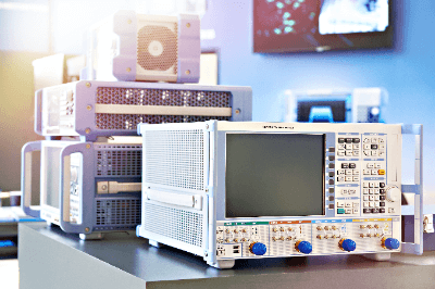
A network analyzer is a test instrument that evaluates the network characteristics of a device under test (DUT). This is done by measuring certain key S-parameters on multi-port networks.

Specifically, it can measure the attenuation and impedance of the input signal to the DUT. In particular, it can evaluate the high-frequency characteristics of electronic components, etc., and has a wide range of applications, including the ability to perform measurements on transmission devices. Such measurements can be conducted on microwave systems, common WIFI networks, corporate networks, basic computer-to-computer connections, and even on large-scale cell phone networks. 

The output of a network analyzer is represented by the S-parameter (scattering parameter), which defines the physical quantities known as forward reflection (S11), forward transmission (S21), reverse transmission (S12), and reverse reflection (S22). This is typically the case with a 2-port network, but the devices or connections being tested may have more than 2 ports. Whatever the network situation, the correct Network Analyzer must be chosen to match the number of ports present. This is a basic premise but an important one if the reflection and loss parameters are to be accurately calculated.

Uses of Network Analyzers

Network analyzers are broadly classified into scalar network analyzers and vector network analyzers (VNA), of which vector network analyzers (VNA), which provide not only amplitude information but also phase information, have a wider range of uses.

The advantages of network analyzers for high-frequency applications are used in the development of matching circuits for high-frequency amplifiers. Here, the design is based on accurate S-parameters for each amplifier, antenna, and/or filter.

In many cases, a network analyzer is also used to evaluate impedance matching. This is because impedance mismatch in the transmission lines of each device or cable in a high-frequency handling circuit network can cause power loss or signal distortion.

Principles of Network Analyzers

A network analyzer is equipped with a signal source, a signal separator, a directional coupler, and at least three receivers.

  • Signal Source                                           
    The signal source provides the signal to the system and is supplied by a synthesizer module.
  • Signal Separator                                        
    The signal separator uses a resistor splitter to split the input signal into circuit signals and receivers (reference signal R).
  • Directional Coupler                                    
    The directional coupler separates the input wave from the reflected wave, which is measured at the receiver (reference signal A).

The output of the DUT is measured at a third receiver (transmission signal B). Evaluation is performed by comparing the signals (e.g., S11 is defined by A/R and S21 by B/R).

Accurate measurement of the network analyzer is ensured by precise calibration. For calibration, a standard device with known characteristics is used. A commonly used calibration method is the SOLT method, in which a short-circuit, open-circuit, and load-capable standard are coupled to a reference plane in a direct connection (thru).

Since this is a very precise measurement, care must be taken to avoid measurement errors in various aspects such as connector tightening torque, ambient temperature, input signal, cable stability, etc.

Other Information on Network Analyzers

1.  Basic Knowledge of Network Analyzers  

There are two types of network analyzers: vector network analyzers (VNA) and scalar network analyzers. Vector network analyzers are widely used these days.

Network analyzers have a method of measuring amplitude changes in transmission and reflection measurements called S-parameters. S-parameters are also called S-matrices, and there is a numbering system for their definition. The numbering scheme is “Sij i=output port, j=input port,” where S11 represents the coefficient of a signal incident at port 1 that has been transmitted to port 1, S12 represents the coefficient of a signal incident at port 2 that is transmitted to port 1.

The S parameter can be measured by using a VNA measuring instrument. However, the VNA must be calibrated using several calibration methods before measurement.

The basic method of VNA calibration is to use three standard instruments. Widely known calibration methods include the SOLT calibration method, the UnKnown Thru calibration method, and the TRL calibration method described above.

2. About Impedance Measurement

Impedance is an important parameter used to characterize electronic circuits, electronic components, and electronic materials. It is the amount of opposition to an alternating current (AC) that interrupts a circuit or other device at a certain frequency. There are various types of impedance measurement methods, each with its advantages and disadvantages.

The measurement method must be selected in consideration of the frequency range required for the measurement and the resistance and reactance conditions of the impedance measurement range. Measurement methods include the bridge method, resonance method, I-V method, network analysis method, time domain network analysis method, and automatic balanced bridge method.

The bridge method is explained as an example. The advantages of the bridge method are its high accuracy (around 0.1%), its ability to cover a wide frequency range with multiple measuring instruments, and its low cost. On the other hand, one demerit of the bridge method is that it requires a balance operation, and a single unit can cover only a narrow range of frequencies. The bridge method’s measurement frequency range is approximately 300-MHz DC.

3. Trends in Frequency Extension

The maximum frequency extension of network analyzers now extends into the sub-THz band (220 GHz). This is because it is predicted that the next generation communication standard, 6G, will most likely use the 140 GHz band, known as the D-band.

However, because of its high frequency, the sub-THz band is susceptible to electrical length errors, parasitic elements, and other measurement discontinuities, making total calibration accuracy, including that of the RF probe tips and cables, extremely important.

In reality, the frequency range that can be calibrated at one time is often limited, and manufacturers are competing to develop easy-to-use measuring instruments, including the handling of data between calibrations and the addition of frequency extenders dedicated to the millimeter wave band.

4. Addition of Modulated Power Evaluation Function, Etc.

Generally speaking, Network analyzers are used to evaluate the impedance of DUTs and S-parameters, which are small signals. Therefore, models that enable network analyzers to perform modulation analysis, which is mainly handled by conventional spectrum analyzers, are gradually being released. With wireless technologies on the increase, the ability to examine complex RF (Radio Frequency) bands is an essential feature, one worth integrating into a Network Analyzer.

In the future, network analyzers will be used not only for impedance and S-parameter evaluation but also for evaluating switches, filters, high-frequency (RF) amplifiers, low-noise amplifiers (LNA), and other RF front ends, including large-signal analysis and modulation analysis.

カテゴリー
category_usa

High Voltage Power Supply Units

What Is a High Voltage Power Supply Unit?

High Voltage Power Supplies
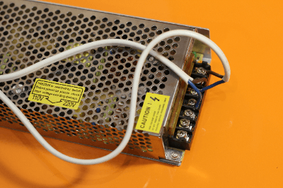
A high-voltage power supply unit is a power supply unit that handles particularly high voltages.

High voltage generally refers to voltages ranging from several thousand volts (V = volts: a unit of voltage) to several tens of thousands of V or higher. The voltage transmitted by power companies is 6.6 kV or higher, but high voltage is generally defined as 600 V AC (750 V DC) or higher.

The electrical appliances we use in our daily lives have low voltages of 100 VAC or 200 VAC. This is due to the fact that the standard power supply voltage transmitted from the power company’s generation facilities to each household is either 100 VAC or 200 VAC.

Although typical power supply units are 100 VAC or 200 VAC, some equipment may want to generate higher voltages depending on the conditions of use. Specifically, these are devices that require higher voltages than the power supply voltage or devices to be tested for tolerance to high voltages. In order to clear this requirement, a transducer that generates higher voltage than the power supply voltage used by general users is needed. High-voltage power supply units are used in such cases.

Uses of Applications of High Voltage Power Supply Units

High-voltage power supply units are mainly used for operating products that require high voltages and to withstand voltage testing.

Examples of equipment that require high voltage include equipment used for painting automobile bodies and construction materials, equipment used for surface treatment of metals and plastics, X-ray radiation equipment used for radiation therapy and x-rays, and electron microscopes.

Pressure resistance testing is performed on industrial electrical equipment such as electric wires. Products are often tested to withstand voltages of 1500 V for 1 minute or 1800 V for 1 second before shipment, and that insulation withstand voltages be tested. Therefore, the introduction of high-voltage power supply units is mandatory. They are also used for practical training to acquire qualifications as high voltage and special high voltage electricity handlers.

Principle of High Voltage Power Supply Units

High-voltage power supply units are converters that input general AC power transmitted to the end of the line and output it as high-voltage. A converter is a device (unit) that converts the AC power supply voltage transmitted from the power company into DC voltage using a circuit with diodes called a rectifier and smoothes the voltage with an electrolytic capacitor.

However, simply using a converter unit will only output a DC voltage that is smoothed at a low voltage because it is 100V or 200V, and will not provide the high voltage of 10 times or 100 times or more the voltage originally desired. It is possible to boost the voltage simply by the turn ratio of the step-up transformer, but the turn ratio has a practical limit.

To obtain a high voltage, a Cockcroft-Walton circuit combining a diode and a capacitor is used. This method uses the storage capacity of the capacitor and the rectifying action of the diode. After the capacitor stores electricity in response to an AC input in one direction, the voltage is boosted when a current flows in the opposite direction.

This circuit method is commonly used to raise the voltage by layering the rectifier-based circuit described earlier and is also referred to as a doubling voltage circuit or a high-voltage generator circuit among technical personnel. Since the voltage increase is an even multiplication, it is not possible to boost the voltage by an odd number of times. High voltages of 1 kV or higher can be obtained by combining an appropriate high voltage diode and ceramic capacitor.

Other Information on High Voltage Power Supply Units

1. High Voltage Power Supply Module

High-voltage power supply modules are high-voltage compatible power supply units capable of supplying high voltages that generally generate 1 kV or more.

Among these, power supply unit manufacturers with an established reputation for their technological expertise in downsizing through higher efficiency while ensuring low noise and reliability have achieved low prices by improving the quantity and ease of use of their products, and have modularized their high-voltage output power supply modules as general-purpose products.

Major manufacturers and products of high-voltage power supply modules include the OHV series by Bellnix, the TCR series by American High Voltage; the HGP series by Matsusada Precision, HitekPower by General Products; the TMK series by Takasago Machinery Works, the C14051 series by Hamamatsu Photonics, etc. The more the output current increases in addition to the original high voltage, the larger the size of the module becomes. Therefore, it is necessary to select a module with attention to its margin, temperature rise, and dielectric strength depending on the actual use of the load. 

2. High-Voltage Power Supply Board

The substrate of a high-voltage power supply is a high-voltage circuit, so there are some precautions that must be taken for the substrate used in the high-voltage circuit. This is because the higher the voltage, the more the standard requires that the insulation distance of the board be sufficiently secured. The higher the voltage is, the greater the possibility of serious electric shock during work. To ensure safety, safety measures against withstand voltage and electric shock must be taken, including the creepage distance and insulation distance of the circuit board and the installation of safety grounding.

In practice, the IEC standard absolutely requires a board pattern design that ensures insulation distances between conductive copper foil patterns on the board based on each country’s standards. Failure to comply with this requirement may result in fines or other penalties as a violation of the law, and not only penalties, but also a loss of social credibility. Therefore, both the manufacturer and the user must be very careful to ensure that the insulation distance of the board pattern meets the standard.

カテゴリー
絶対に触らないでください(日本会社ニュース)

株式会社ライカマイクロシステムズ様のMetoree導入事例を掲載しました

株式会社ライカマイクロシステムズ様のMetoree導入事例を掲載しました。

https://metoree.com/guides/47672/

カテゴリー
製造業マーケティングガイド

【事例紹介】ライカマイクロシステムズ株式会社様


複数の業務に関わる担当者が新規顧客の流入を片手間で増やした方法


「From Eye to Insight」をビジョンとして掲げ、創業から170年以上光学顕微鏡の製造・販売を手がけているライカマイクロシステムズ株式会社。

ライカ マイクロシステムズでは外資系企業では珍しく、日本法人として自社サイトを運営しており、オンラインマーケティングにも力を注いできました。しかし、営業責任者である矢倉様がマーケティング業務を兼務で行っていたため、充分なSEO対策などを行うことができず、自社サイトへの流入数が増えないことに課題感を感じていました。

兼務しながらでも、自社サイトの流入数を伸ばし、新規顧客を獲得するためにSEO(検索エンジン最適化)や掲載の手軽さに強みを持つMetoreeの導入を決断しました。その背景や導入に対してのハードル、導入してからの変化などについて矢倉様に伺いました。


無料掲載ご希望の方はこちら


170年以上の歴史を持ち、質の高い光学顕微鏡を届ける


―はじめに、御社の事業についてお教えください。

矢倉さん(以降、矢倉):世の中的にはライカというとカメラのイメージが強いと思いますが、これは関連会社のライカカメラという会社が行っている事業です。弊社は、「From Eye to Insight」をビジョンとして掲げ、創業から170年以上光学顕微鏡の製造・販売を行っております。大学や病院などで利用される高度な顕微鏡から、一般企業で利用される顕微鏡まで幅広く販売させていただいております。

―矢倉さんの役割についても教えてください。

矢倉:その中で私は主に製造業企業向けの販売を担当するインダストリーの事業部の営業責任者を務めており、傍でマーケティング業務を行っています。メインの営業責任者としては営業チームのマネジメントやKPI管理、チームの環境づくりなどを行っております。マーケティング業務は専任がいないため、広告出稿やコンテンツ作りなど幅広く担当させていただいております。


サイトへの流入数を増やすためにMetoreeを選択


ーMetoree掲載前はどのように問い合わせの獲得をしていたか教えてください

矢倉:コロナがはやる前は、オフラインのイベントや展示会への出展を通してリードの獲得を行っていました。イベント出展以外にもオフライン、オンライン問わず広告出稿を行っていました。コロナの影響でイベントなどを行えなくなったことも大きかったのですが、投資対効果の観点でも会社としてオンラインでのリード獲得に力を入れていきたいという考えはありました。

また、弊社は外資系企業では珍しく、日本法人として自社サイトを運営しております。兼務でマーケティング業務を行っているため、積極的に運用できるわけではありませんが、自社サイトのコンテンツの拡充をすることでサイトへの流入を増やし、リード獲得に繋げていました。

ーどんなところに課題があったか教えてください

矢倉:大きく分けて二つ課題がありました。一つ目はコンテンツを作りづけるリソースが足りなかったことです。先程もお話ししましたが、マーケティングは私が兼業で行っているため専任の担当者はいません。そのため、魅力的なコンテンツを継続的に作り続けることは難しい状況でした。

二つ目は流入を増やすことができなかった点です。自社サイトを運用しているため比較的自由にコンテンツを増やすことはできましたが、リソースが不足していたためSEO(検索エンジン最適化)対策などを行うことができず、コンテンツを増やしてもサイトへの流入が増えないという課題を感じていました。

ーどんな経緯で広告を出すことになったんですか?

矢倉:元々オフラインの広告媒体やGoogleのリスティング広告などで広告出稿自体は行っていました。しかし、こちらもリソース不足で運用が回っておらず、新規顧客の獲得には繋がっていない状況でした。そんな時に関連会社からMetoreeを紹介してもらいました。

MetoreeはSEOに強みを持っており、当時からGoogle等の検索エンジンで光学顕微鏡関連のキーワードで検索すると上位に表示されていました。自社サイトへの流入数が大きな課題になっていたので、流入数を増やすための新しいチャネルとしてメトリーさんへ掲載をお願いすることにしました。


月間問い合わせ数の1割をMetoree経由で獲得


ー広告媒体は他にもあったと思うのですが、なぜMetoreeを選んだのですか?

矢倉:もちろん他の媒体への広告出稿も考えましたが、一番の決め手は掲載の手軽さと掲載へのスピードだと考えてます。どうしてもマーケティング業務を兼務しているため、コンテンツを自ら作成して更新し続けることは、手間も時間もかかってしまいます。また一般的に記事広告などの掲載には数ヶ月かかるケースが多く検証までに期間がかかります。

Metoreeは、リンクと商品説明のバナーやテキストだけ用意するだけで、掲載することを決めた日から1日〜3日程度で手軽に開始することができることが大きなメリットだと感じています。また、Metoree自体がSEO対策がしっかりされているので、多くの製品ページがGoogleで上位表示されています。そのためコンテンツを自社で作成しなくてもいいので、兼務している私でも続けることができると思いメトリーの導入を決めました。


ー掲載後はどのような効果がありましたか?

​​矢倉:Metoree掲載後は、ホームページへの流入数を増やすことができ、月間問い合わせ数の1割はMetoree経由で獲得することができています。また、リスティング広告などと比べると、ターゲットとしているお客様が問い合わせをいただいている印象があります。

リスティング広告では、どうしてもターゲットとしていない属性のお客様が入ってきてしまうこともありました。Metoreeは産業用製品専門の製品情報比較メディアなので、一定フィルタリングされているため、ターゲットになるお客様が多い印象を受けています。


手軽さと無料で始められることがメリット


ーMetoreeに掲載するなら、どんな課題を持った方がおすすめですか?

矢倉:Metoreeの1番のメリットは、しっかりと流入数を増やすことができる媒体でありながら手軽に始められることだと考えています。実際に私もマーケティング業務を兼務しながら2年ほど運用をすることができています。そのため、業務を兼務していて自社のSEO対策に手が回らない人やマーケティングを兼務している人などにお勧めしたいです。また、無料から始めることができるので広告出稿の経験がない方でも気軽に始めることができると思います。


無料掲載ご希望の方はこちら


ライカマイクロシステムズ株式会社様の会社HPはこちら

ライカマイクロシステムズ株式会社様のマイクロスコープ紹介ページはこちら


無線リモコン

無線リモコンとは

無線リモコンとは、電波を使用することで遠隔操作を可能にするリモートコントローラーのことです。

一般的にリモコンと言うと、テレビや、ホビー用ラジコンなどを赤外線などの近距離無線通信によって操作するための装置のことを指します。家庭用のリモコンは、経路を遮られると通信できなくなったり、対象物からの距離が離れると安定して使えなくなったりする特徴があります。

一方で、産業用の無線リモコンは、家庭用リモコンのデメリットを克服して、安全性や作業性に考慮されています。

無線リモコンの使用用途

無線リモコンの使用用途には、テレビやエアコン、ガレージシャッターなどを操作する家庭用リモコンなどがあります。

産業用のリモコンの使用用途としては、天井クレーン (クラブ、ホイスト、チェーンブロック) 、タワークレーン、搬送台車、建設機械 (ブルドーザー、ショベルローダー、ショベルカー、ローラー車) 、各種工業設備などに使用される産業用のリモコンなどが挙げられます。

また、近年では、スマートフォンやタブレットを使いWI-FIを経由した操作を普及してきています。

産業用の無線リモコンは、安全性を高めることや、作業効率を上げて操作することや、過酷な作業現場に耐えられる耐久性やメンテナンス性などが考慮されています。産業用の無線リモコンはテレコンと呼ばれ、ホビー用の無線リモコンとは区別されています。

無線リモコンの原理

基本的に無線リモコンは、送信機と受信機で構成されます。
スイッチなどの制御信号を電波にして送り、受信した電波を制御信号に変換して制御します。

よってリモコンの送信キーを押すと、送信信号データを電波でON/OFF 信号を識別できるように変調を行います。変調されたデータを適切な周波数に発振し電波をだします。その電波を受信機で、受信し、必要な周波数を抽出しそのデータの復調を行い、もとのON/OFF 信号に戻して出力を行います。

無線リモコンの選び方

無線リモコンを選定する場合、手軽さ、正確性、安全性、耐久性などを考慮する必要があります。操作を誤っても特に問題ない場合は、手軽かつ安価に購入できるホビー用や、汎用のリモコン、または、スマホやタブレットなどを選択すれば良いですが、対象物が正確に且つ安全に、操作することが必要な場合は、産業用の無線リモコンを用いることをおすすめします。

更に、作業する場所が過酷な環境の場合は、温度、湿度、強度、メンテナンス性なども考慮する必要があるでしょう。

もう一つの要素として、無線リモコンに使用する周波数にも注意する必要があります。

家庭用やホビー用などでは赤外線を用いたリモコンも多くありますが、対象物の方向にリモコンを向ける必要性や、外乱光の影響を強く受けるため、産業用として使用するには不向きになります。

また、産業用のリモコンでは、主に、300MHz帯、429MHz帯、1.2GHz帯、2.4GHz帯などが主に用いられます。最も普及しているのは、2.4GHz帯で、世界標準で規格された周波数帯になるため、製品の種類も多く価格も低いものが一般的です。しかし、この周波数帯は、無線LANや、Bluetooth、電子レンジなど多くの製品で用いられているため、混信などの影響が懸念されます。 産業用の無線リモコンでは、多くの台数を同時に使用することを想定した製品もあり、購入先に訪ねてみることをおすすめします。

次に、429MHz帯、1.2GHz帯は、2.4GHzほど使用されておらず、確実に無線を通信したい場合に向いている周波数帯です。

300MHz帯は、無線出力を多く出せない周波数帯域になり、通達距離は短くなるのですが、出力が小さいため、多くの無線リモコンを比較的近くで使いたい場合には考慮できる周波数帯になります。

無線リモコンのその他情報

1. 変調方式の種類

一次変調方式

  1. ASK(振幅偏移)
    振幅を変える変調方式、RFID、ETC、JJYなどで使用されています。
  2. FSK (周波数偏移)
    周波数を変える変調方式、高い周波数には向かないが電力効率も良く簡易な回路で使用できるため、Sub-GHzで多く採用されています。MSKは、変調指数が 0.5の位相連続 FSKのことを指します。
  3. PSK (位相偏移)
    搬送波の位相を変える変調方式です。GPSや、ZigBeeで使用されています。
  4. QAM (直交振幅変調)
    振幅と位相の両方を変える変調方式です。振幅と位相の両方を使っているので、PSKの2倍の伝送速度を得ることができます。しかし、誤り率も高くなってしまうため、送信電力も上げる必要があります。 LTEや、地上波デジタル放送などで使用されています。

二次変調方式
一時変調した搬送波を広い帯域に拡散して送信する方式です。大きくは拡散方式と多重化方式に分けられ、拡散することで他の通信の影響を受けにくくなります拡散方式と、複数の通信を行う多重化方式があります。

  1. DSSS (直接拡散)
    疑似乱数波形で拡散する方式。 無線 LAN や ZigBee で採用
  2. FHSS (周波数ホッピング)
    常に周波数を移動しながら通信 Bluetoothで採用

2. 周波数について

電波法第2条の1で、「電波とは、300 万メガヘルツ以下の周波数の電磁波をいう」と定義された電磁波の一種です。電波、赤外線、可視光線、紫外線、X線、ガンマ線なども電磁波に属します。

電波は周波数によって特徴が異なり、低い周波数は下記のような特徴があります。

  • 減衰が小さく通達距離が長くなる
  • 回り込みやすく障害物に強い
  • 情報量が少ない

また、高い周波数では下記のような特徴があります。

  • 減衰が大きく通達距離は短くなる
  • 直進性が高く障害物に弱い
  • 情報量が大きい

3. 技術基準適合証明について

日本国で無線を使用する際はほとんどの場合、当該無線局が記述基準に適合していることを検査することが必要になります。

ただし、小規模な無線局利用においては、総務省令で定める「技適マーク」をメーカーや輸入業者が取得することで、検査の省略が可能になります。特に、海外製の無線機を輸入して使用する場合は、技適マークがついていない場合があり注意が必要です。一般に使用する無線機の殆どに特定無線設備の技術基準適合証明等のマーク (技適マーク) が付いています。

免許を受けずに無線局を開設もしくは運用した場合は電波法違反となり、1年以下の懲役又は100万円以下の罰金の対象となります。また、公共性の高い無線局に妨害を与えた場合は、5年以下の懲役または250万円以下の罰金の対象となります。

参考文献
https://www.tele.soumu.go.jp/j/adm/monitoring/summary/qa/giteki_mark/

カテゴリー
絶対に触らないでください(日本会社ニュース)

Metoreeを運営するZAZA株式会社が豊橋技術科学大学「豊橋技術科学大学基金」への寄付を行いました

メトリーを運営するZAZA株式会社が豊橋技術科学大学「豊橋技術科学大学基金」への寄付を行いました。

メトリーでの収益を還元することにより、より一層の科学技術の発展を目指す一員として微力ながらこれからも貢献をしていく所存です。

また寄付について積極的に発信していくことで、学術・教育領域への寄付文化が少しでも広がることを目指して参ります。

寄付先についても常時検討をしておりますので、こちらよりご連絡頂けますと幸いです。


豊橋技術科学大学「豊橋技術科学大学基金」について

https://www.tut.ac.jp/kikin/

メトリーへのお問い合わせについて

https://metoree.com/contacts/