カテゴリー
category_usa

Separators

What Is a Separator?
Separators

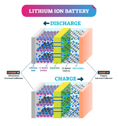
A separator is a component that separates the positive (anode) and negative (cathode) electrodes of a secondary battery to prevent electrical contact between the positive and negative electrodes and ensure ion conductivity. The types of batteries include nickel-metal hydride batteries, lithium-ion batteries, fuel cells, and more.

Although specifications differ depending on the battery type, such as nickel-metal hydride batteries, lithium-ion batteries, and fuel cells, the common feature is that it is a component that facilitates the fundamental electrochemical reaction between the positive and negative electrodes.

For example, in a lithium-ion battery, lithium ions (Li+) and electrons move in and out between the positive (anode) and negative (cathode) electrodes to charge and discharge the battery.

This is achieved by creating a small hole in the separator to allow lithium ions to pass through.

Application of Separators

In this section, we will describe an example of the application of separators used in lithium-ion batteries. With the proliferation of tablet PCs and electric vehicles, there is a growing demand for lithium-ion batteries with higher capacity and energy density.

Separators are used to insulate the positive (anode) and negative (cathode) electrodes, prevent abnormal heat generation due to short circuits, and facilitate the charge and discharge of the battery through proper ionic conduction between the positive (anode) and negative (cathode) electrodes.

Here are some examples of separators used in lithium-ion batteries:

  • Separators for automotive laminated lithium-ion batteries
  • Separators for automotive rectangular lithium-ion batteries
  • Separator for a laminated lithium-ion battery for smartphones

Principle of Separators

This section explains the principle of separators used in lithium-ion batteries.

Lithium-ion batteries are charged and discharged by the conduction of lithium ions between the positive and negative electrodes, and an electrolyte is injected to facilitate the conduction of lithium ions. During this process, if electrons are conducted through the electrolyte, electricity cannot be transmitted to the external circuit. Therefore, a separator is placed between the positive and negative electrodes to allow only lithium ions to pass through and prevent internal short circuits caused by contact between the positive and negative electrodes.

As a result, the separator must possess ion conductivity and electrical insulation properties. Additionally, it requires materials that are electrically, chemically, and mechanically robust to ensure stable battery operation. For this reason, separator materials and shapes are modified in various ways depending on the application to enhance the efficiency of the electrochemical reaction of lithium ions from the positive electrode (anode) to the negative electrode (cathode).

Examples of Technological Innovations in Separators

Fluoroplastic Coating

  • Objective: To enhance adhesion in the production of laminated cells
  • Summary: The use of fluoropolymer coating enables strong adhesion between electrodes (positive and negative electrodes). Separators are gaining attention as a technology that can prevent cell deformation, improve the C-rate, and develop structures that lead to higher capacity.
カテゴリー
category_usa

OA Floors

What Is a Raised Access Floor?

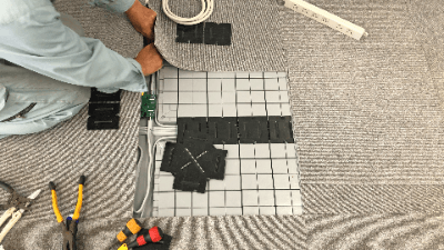
Raised FloorsA Raised Access Floor is a floor with a fixed height space under the floor. The purpose is to pass network wiring, etc., which tend to become cluttered, through the space under the floor. It is also known as free-access floor or a double-layered floor.
Raised Access Floors do not affect the placement of desks and cabinets, making it easy to change wiring later. They also prevent damage to wiring and other hazards caused by human traffic and moving chairs.

Raised Access Floors have many advantages, such as improved aesthetics and easier cleaning.

Uses of Raised Access Floors

Raised Access Floors are installed in offices, factories, commercial facilities, schools, and other locations where many computers, servers, printers, network equipment, telephones, video equipment, and other electronic devices are used.

In the past, Raised Access Floors were used in computer rooms where large computers were installed in large organizations such as large corporations. Recently, however, due to the increase in the number of PCs and other OA equipment, and the spread of network environments such as LAN and Ethernet, OA floors are commonly used regardless of the size of the office.

When installing, it is important to estimate in advance the number of wires and load required. After installation, the wiring paths cannot be followed visually without opening the floor, so it is necessary to attach tags with numbers and destinations to the wiring ends and record them in drawings and management books.

Principle of Raised Access Floors

Raised Access Floors can be broadly classified into two types according to its structure: laid-in type and pillar separation type.

In addition, the wiring system can be roughly classified into two types: under-panel wiring system and groove wiring system.

1. Laid-In-Place Type

In the laid-in-place type, the pillar and panel are laid out as a single block. Most of them are made of resin, which makes on-site processing relatively easy, and the materials themselves are inexpensive, making them cost-effective. In this type, the floor height is fixed and cannot be changed later.

Because the degree of freedom in height adjustment is limited, this type is inherently unsuitable for installation in locations where the floor slab of a building has a difference in height and is not flat. However, there are products that can adjust the height using spacers. Due to the load-bearing capacity of the material used, these products are not suitable for installation of heavy objects.

2. Pillar Separation Type

In the pillar separation type, a pillar is erected on the floor and a board-like panel is placed on top of it. The height can be freely adjusted and the load capacity is excellent. The panel that makes up the floor and the support columns that determine the height are independent components, and the height of the columns can be adjusted, allowing the height of the floor to be adjusted as desired.

Therefore, the panel is suitable for use where there are steps or height differences in the floor of a building. And since metal products are the main material used for the panels, they are suitable for installation of heavy objects. In addition, there are products in which the panels are filled with mortar, which improves heat and sound insulation.

3.Under-Panel Wiring Method

The under-panel wiring method is a method of storing wiring in the cavity between the posts and legs, and has the advantages of large wiring storage capacity and a high degree of wiring flexibility. In the case of the separate-pillar type, the storage capacity can be further increased by increasing the height of the pillars. The disadvantage is that there is a possibility of interference.

4. Groove Wiring Method

In the groove wiring method, wiring is done along the groove of the panel, and a cover is placed over the top to protect the wiring. This method has the advantage of facilitating wiring changes and additions. Although the wiring storage capacity is small, wiring is done in an orderly fashion along the grooves, preventing interference. The groove wiring method is suitable when the number of wires is small or when there are plans to change the layout or increase the floor space.

Other Information on Raised Access Floor

Advantages and Disadvantages of Raised Access Floors

Advantages

  1. It has a cleaner appearance and improves work efficiency.
  2. Wiring outlets can be changed, allowing free layout changes of desks and PCs.
  3. Reduces problems such as falling over due to feet getting caught in wiring or data errors due to wiring disconnections, etc.
  4. Floor cleaning becomes easier.

Disadvantages

  1. Raised Access Floors have a limited load-bearing capacity and are restricted to heavy equipment. Also, since the height cannot be adjusted, they are not suitable for floors with slopes.
  2. Raised Access Floors with separate support columns have heavy metal parts, which may cause problems in workability and load-bearing capacity of the building.
  3. Depending on the equipment used, durability and walking feel may be defective. It is important to confirm this through testing.
カテゴリー
category_usa

KVM Switches

What Is a KVM Switch?

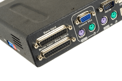
Keyboard/Video/Mouse (KVM) SwitchesA KVM (Keyboard/Video/Mouse) Switch is a piece of hardware that allows you to control multiple computers with a single keyboard, display (video), and mouse. It is also sometimes referred to as a CPU Switcher or PC Switcher.

Basically, a single pair of KVMs control multiple computers, but some products allow multiple KVMs to control a single computer. The more versatile KVM switches also offer the ability to share USB devices and speakers. They can also be used for data servers as well as computers.

Uses of KVM Switches 

KVM Switches can be used in the home, but are most commonly used in industrial and commercial applications. Some examples are listed below:

  • Data centers with many servers running
  • Factories, offices, and laboratories with multiple PCs
  • Factories with a structure or layout that makes access to the PCs difficult
  • Large premises or locations where multiple PCs are installed.

Principle of KVM Switches

KVM Switches connect the cables from each device to the switch and outputs to the computer via a special cable that combines USB and VGA.

There are two types of KVM switches: passive and active, each with a different principle; the characteristics of the PC and OS will affect the compatibility of the KVM switch, so an appropriate switch must be selected.

1. Passive KVM Switch

Passive KVM Switches, also known as Mechanical KVM Switches, physically switch the electrical circuitry. PCs are switched by select switches or pushbuttons.

While the structure is simple and inexpensive, the maximum number of PCs that can be connected is limited to 12. Also, since the interface device is perceived as physically disconnected from the unselected PC, it may fail to boot or boot without a mouse, depending on the PC and OS. 

2. Active KVM Switch

Active KVM Switches, also called Electronic KVM Switches, use simulated signals to switch between peripheral devices. Unlike Mechanical KVM Switches, they emulate the connection of an interface device to a non-selected PC. This prevents non-selected PCs from failing to boot.

Active KVM Switches also work well with PCs and operating systems that continuously monitor the connection status of interface devices, and switching between PCs can be done by quickly pressing a specific key, eliminating the need to touch the KVM switch itself for convenience.

KVM Switch with Long-Distance Communication

KVM Switches are available as Remote KVM devices that can be operated from long distances. There are two types of remote KVMs, analog KVM and digital KVM, depending on the control method.

1. Analog KVM

Analog KVM Switches are designed for operation over a distance of up to 300 meters. A LAN cable is used for connection, but the communication protocol is proprietary to the product, so it cannot be connected to other LAN devices.

Because it uses a proprietary protocol, it does not have much communication delay time. 256 or more access points can be configured, and more than 8,000 PCs can be controlled.

2. Digital KVM

Also called KVM Over IP, Digital KVM can send and receive signals over the Internet via Ethernet communication. Although there is a slight delay in operation due to the use of the Internet, it can operate over a longer distance than analog KVM. Because of this characteristic, they are also used for remote work.

Most digital KVMs allow remote control of PCs via a browser or dedicated viewer software. Remote software that can remotely control a PC over the Internet includes VNC and terminal services. Digital KVM Switches have the advantage over them in that they do not require the installation of remote software.

発泡スチロール加工

監修:株式会社坂本設計技術開発研究所

発泡スチロール加工とは

発泡スチロール加工

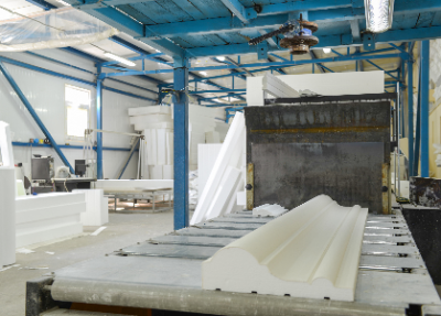
発泡スチロール加工とは、発泡スチロールを用いて造形物を作る工程のことです。

発泡スチロールは用途と製法により3種類に分けられます。一般的に発泡スチロールとよばれているものは「EPS」という種類で原料となるビーズを発泡させて作られます。

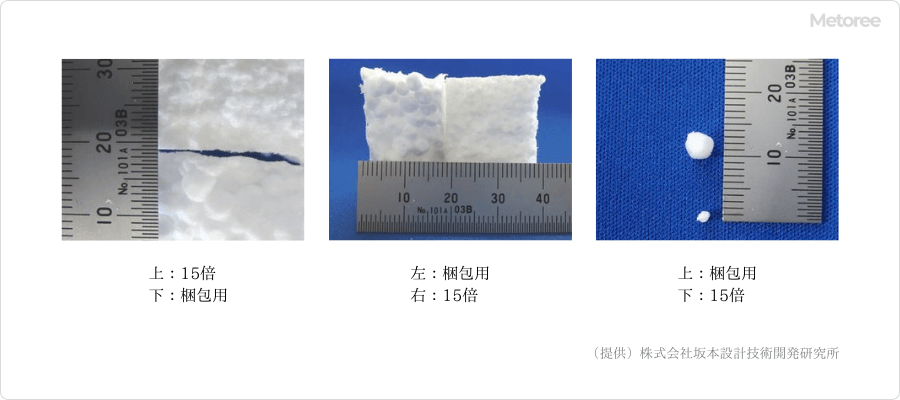
原料ビーズから発泡スチロールへと発泡させた時の倍率 (容積比) を「発泡倍率」と呼びます。大きく膨らませる (発泡倍率が高い) ほど、柔らかい発泡スチロールとなります。

発泡ビーズの比較

図1. 発泡ビーズの大きさ比較


一般的な緩衝材に用いられている発泡スチロールの発泡倍率は50〜60倍です。一方、造形物等の加工には15〜60倍の倍率の発泡スチロールが使われます。強度や精度を必要とする場合は15倍、一般的な造形加工やFRP用の原型として使用する場合は50〜60倍など、造形物の用途によって使い分けられます。

加工方法にも種類があります。発泡スチロールブロックをナイフやカッターなどを使用して手作業で切削する方法と、NC加工機等を使って3Dデータをもとに加工プログラムを作成し、人の手を加えずに切削する方法です。

NC加工の場合、切削物の3Dデータと加工プログラム (NCデータ) によって切削するため、CAD/CAMなどのソフトウエアや、専用の工作機械やそれを扱う専門のオペレーターが必要ですが、手作業に比べると職人の熟練度やコンディションに左右されない安定した品質を確保することができるため、量産に向いています。

発泡スチロール加工の使用用途

以下に、使用例の一部を挙げます。

  • 大型模型製作
  • FRP用の原型製作
  • 展示会用拡大/縮小模型の製作
  • 工業製品のデザイン・形状確認用模型の製作
  • 3Dデータから発泡スチロール模型の製作
  • 模型の量産製作
  • 文化財や芸術品の保存、複製

発泡スチロール加工は様々な用途の造形物製作に利用されています。3Dデータを使用して機械で加工することにより、データに忠実な模型が製作でき、拡大・縮小や量産、短納期化にも適しています。そのため近年では、各種イベントやアミューズメントパーク、ショールーム、芸術関連といった多種多様な分野において3Dデータ加工の需要が増えています。

発泡スチロール加工の原理

発泡スチロール加工には、熱線等で2次元的にカットする方法と、NC加工機やマシニングセンタ等を用いて3次元的に切削する方法があります。

2次元熱線加工はニクロム線に熱を通して溶かしながらカットします。発泡スチロールの原反をスライスしたり、2次元形状にカットする際にはこの方法で加工します。

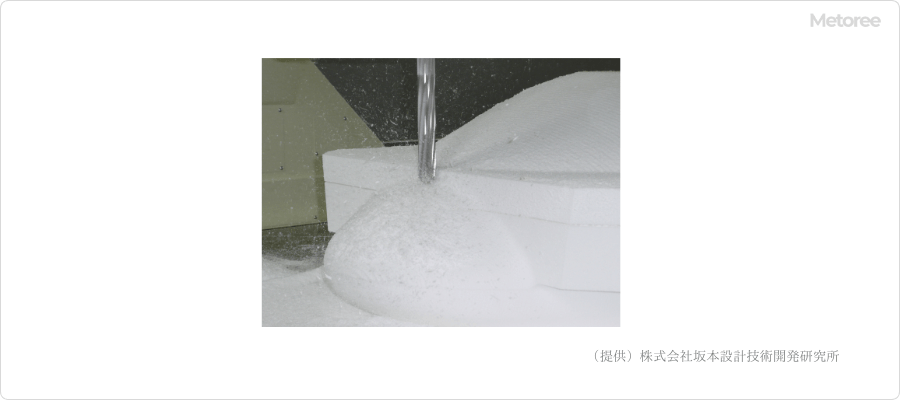
一方、3次元切削加工はNC加工機やマシニングセンターに取り付けたドリルや図2のようなエンドミルで切削します。NC加工機とは、数値制御 (英: Numerical Control) によって位置や速度を自動で制御して加工する工作機械です。この工作機械を動かすためのプログラムをNCプログラムと呼びます。

エンドミル加工

図2. エンドミル加工


3Dデータを元に切削物の形状や、材料となる発泡スチロールの硬さに応じて最適な加工方法を検討し、CAD/CAMを使用してNCプログラムを作成します。曲面を伴う3次元形状を造形する場合は、この方法で加工します。手作業や熱線でのカットに比べ、3Dデータに忠実な模型が製作できるため、精度が必要な造形物や2つ以上の模型の製作には特にメリットがあります。

発泡スチロール加工のその他情報

1. 発泡スチロール加工の種類

発泡スチロールは様々な形状に加工されます。加工手法としては、以下のような方法があります。

  1. 直線加工
  2. 曲線加工
  3. 溝加工
  4. 穴あけ加工
  5. 切削加工

このような加工をおこなう手段としては、以下のような方法があげられます。

熱線 (ニクロム線) 加工

発泡スチロールの加工には電熱線がよく使用されています。これは、発泡スチロールに熱が伝わると溶融して表面が滑らかになるためです。具体的には、電熱線を用いて発泡スチロールのブロックをスライスして板状にカット加工したり、電熱線により加熱しつつNC加工機によって円柱や六角柱といった様々な形状に切り抜くことができます。この技術を応用するとキャラクターのシルエットや文字などの形状への加工も可能で、これを用いた看板や立体ロゴはよく利用されています。

刃物加工

発表スチロールの切削加工

図3. 発泡スチロールの切削加工


  1. トムソン加工
    木型を作り、トムソン刃を用いてプレス  (打ち抜き) 加工する方法です。打ち抜き加工なのであまり細かい形状の加工には向きません。熱線加工よりも早く加工できるのがメリットです。
  2. エンドミル加工 (切削) 
    ドリルの様な形状のエンドミルという工具を使用した方法です。このエンドミルは穴あけだけではなく、側面の切削もできます。複雑な3次元形状のものや、継ぎ接ぎが不可な加工品などに好適です。
  3. ホルソー加工 (穴あけ) 
    工具を電動工具に取り付けて穴を開ける方法です。
  4. のこぎり・カッター
    DIYなど一般的なユーザーも手加工時に多く利用する方法です。発泡スチロール専用のカッターなども販売されています。加工業者においても細かい仕上げ作業などに使用しています。

2. 発泡スチロール加工における一体加工と分割加工

発泡スチロール加工により造形物を製造する場合、一体ものとして加工する一体加工といくつかのパーツに分けて加工して接着やはめ込みなどで組み合わせて最終形状とする分割加工があります。

サイズが小さいものや一体ものとして加工が可能な形状のものの製作には、一体加工が一般的です。一方、イベントや展示会場で使用するような大掛かりな造形物に関しては、搬入搬出・発送・納品などの点から分割加工を行い現場で組み立てることも多くあります。

この場合、発泡スチロールは接着可能な材質であるため接着による組み立てが可能です。各パーツに切り欠きなどの目印をつけることも可能で、組み立てられる形状に加工しておくことも可能です。

なお、発泡スチロール加工においては上から見て俯角 (影) に入った形状のものは基本的に一体加工が難しく、分割加工が必要となります。

3. 発泡スチロール加工における表面処理加工

発泡スチロール加工により製作された造形物には表面処理加工が可能で、表面にウレタンコーティングする、塗装するなどの処理があげられます。

ウレタンコーティング
表面のウレタンコーティングは、発泡スチロールにウレタン吹付加工を施しておこないます。ウレタンコーティングを施すことにより、耐候性や耐久性の向上が可能です。イベントなどの人が触れる可能性が高い場所への設置物や、イベントなどで繰り返して使用する場合、屋外で使用する場合などに向いています。ウレタンを吹き付けた面に少し凹凸ができますが、パテ埋めやサンディング加工などで滑らかな面に加工できます。

塗装
発泡スチロールは水性の塗料により塗装が可能です。油性塗料は発泡スチロールを溶解させてしまうため、使用できません。メーカーによっては、色番号の指定などに対応しているところもあります。

参考文献

https://www.s-sst.com/service/design-technology/modering%ef%bc%86nc/
https://www.daiichi-foam.co.jp/technology
https://www.s-sst.com/service/design-technology/modering%ef%bc%86nc/faq/
https://www.matsubara-sangyo.jp/faq/eps26/

本記事は発泡スチロール加工を製造・販売する株式会社坂本設計技術開発研究所様に監修を頂きました。

株式会社坂本設計技術開発研究所の会社概要はこちら

カテゴリー
category_usa

FRP Grating

What Is Fiberglass Reinforced Plastic (FRP) Grating?

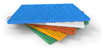
Fiberglass Reinforced Plastic (FRP) GratingsFiberglass Reinforced Plastic (FRP) Grating is a grating made of FRP. It is a relatively new material and is mainly used for buildings.
FRP is an acronym for “Fiber Reinforced Plastics”. It is a material that combines plastic resin and glass fiber, and its strength is comparable to that of metal, even though it is plastic. Since it does not corrode, it is widely used in factories and outdoors where corrosive substances are handled.

Uses of Fiberglass Reinforced Plastic (FRP) Grating

FRP Grating is used in various places as a construction material. In daily life, they can be found in aquarium corridors and drain covers. This is because corrosion by seawater will occur if grating made of metal material is used.

In industrial applications, grating is used in flue gas desulfurization plants. FRP is also used for flue gas desulfurization plants, and FRP material is very useful for flue gas desulfurization plants.

Principle of Fiberglass Reinforced Plastic (FRP) Grating

FRP is reinforced by mixing glass fiber with plastic. The strength is increased by mixing glass fiber, which has a high elasticity rate and is strong, with plastic, which has a low elasticity rate and is prone to cracking.

FRP Grating is lighter than metal grating. Specifically, its specific gravity is about 25% that of cast iron and 60% that of aluminum, and it has excellent corrosion resistance. When utilized as a construction material, FRP grating is easier to process than metal grating. However, being a mixture of plastic and glass fiber, it is difficult to recycle or dispose of.

FRP Grating can be colored either by surface coating or by adding pigments during the molding process. Mixing the pigments during the molding process is advantageous because it prevents the surface from peeling off.

Use of Fiberglass Reinforced Plastic (FRP) Grating as Flooring Material

FRP Grating is a lightweight material with excellent corrosion resistance. Therefore, FRP grating is suitable for flooring in corrosive environments such as chemical plants and ships where load reduction is required. FRP Grating with a non-slip shape can also help prevent pedestrians from falling.

FRP Gratings have high lighting performance, allowing light to reach the first floor through windows on the second floor of a house. It is also possible to change the impression by changing the color. When used as a flooring material, it may cause pain standing barefoot for long periods of time. For places where people stand for long periods of time, polycarbonate is placed on top of the grating to distribute the weight.

FRP Grating can also be used for bridge floor panels, stairs, etc. because it is an insulator, allows radio waves to pass through, and can be easily colored.

Other Information on Fiberglass Reinforced Plastic (FRP) Grating

1. Strength of Fiberglass Reinforced Plastic (FRP) Grating

FRP Grating can withstand up to 350 kg per square meter, and its service life is estimated to be 20~30 years based on the results of outdoor exposure and accelerated exposure tests. Yellowing of the exterior due to ultraviolet rays will occur after 5~10 years of use. This yellowing can be improved by painting.

FRP Grating is impact resistant to full impact. However, there are limitations on impact resistance due to puncture and falling load, so it is necessary to check the information of the manufacturing manufacturer.

The heat resistance of general FRP gratings are about 65~80℃, which is not as high as that of metal. FRP Grating made of a special resin should be used for use under high temperatures. 

2. Outdoor Use of Fiberglass Reinforced Plastic (FRP) Grating

FRP Gratings have high weather resistance, and their strength hardly deteriorates due to temperature changes. Therefore, they can be used outdoors. Examples of outdoor applications include balcony flooring, plant walkways, stair treads, drain covers, and exterior wall partitions.

生化学用緩衝剤

監修:株式会社同仁化学研究所

生化学用緩衝剤とは

生化学用緩衝剤

緩衝液とは、酸や塩基を加えてもpHがあまり変化しない溶液をいいます。
適当な弱酸とその共役塩基の混合溶液が pH 緩衝液として利用されています。

生体成分の分離・精製や細胞培養を行なうにあたっては、溶液内の pH をー定に保つ必要があります。陸生生物の生体成分の pH は通常6.5~7.5 で、海生生物とくに海藻類は pH8 程度であるため、生化学用途としては pH6~8 の範囲を緩衝できるものでなければなりません。

1966年、Goodらは生化学用緩衝剤としての望ましい条件を考慮して、Zwitter ion 構造をもつ各種のアミノエタンスルホン酸、アミノプロパンスルホン酸誘導体を合成し、その有用性を明らかにしました。これらはGood’s bufferと呼ばれ、以下に示すような特長をもっています。

また、分子生物学研究に用いる緩衝液は、実験内容に応じてDNaseやRNaseなどbuffer中に検出されないことも必要です。

Good’s Bufferの特長

  • 水に良く溶け、濃厚な緩衝液が作成できる。
  • 生体膜を透過しにくい。
  • 酸解離平衡が濃度、温度、イオン組成の影響を受けにくい。
  • 金属イオンとの錯形成能が小さい。
  • 化学的に安定で、再結晶による高純度精製が可能。
  • 可視、紫外部に吸収を持たないために、目的成分の検出が容易である。

生化学用緩衝剤の使用用途

生化学用緩衝剤 (Good’s buffer) は、生体成分の分離・精製や細胞培養を行う際の培地の緩衝剤、タンパク質の精製等幅広い用途で使用されています。使用する実験系やサンプル、目的とするpHに応じて、生化学用緩衝剤 (Good’s buffer) の選択が必要となりますが、実験手法によっては適さない生化学用緩衝剤 (Good’s buffer) もありますので、注意が必要です。

生化学用緩衝剤の原理

培養細胞の特性や培養細胞を構成する生体物質における酵素による触媒反応や核酸などの化学反応は、溶解している溶液の水素イオン濃度指数 (pH) の影響を大きく受けます。そのため培養細胞溶液のpHをほぼ一定に保つことが非常に重要です。

生化学用緩衝剤はこの働きをしており、pHを一定に保つために溶液内に水素イオンを供与できる酸 (HA) とこれを受容できる共役塩基 (A–) を含有します。水素イオン濃度が減少 (pHが上昇) した時には酸であるHAが、H+とAに解離することでpHを一定に保ち、水素イオン濃度が増加 (pHが低下) した時には共役塩基であるAが水素イオンH+と結合して酸 (HA) となって、溶液中の水素イオン濃度 (pH) を一定に保つことが可能です。

生化学用緩衝剤(Good’s buffer)の代表的な一つであるHEPESを参考に解説します。

HEPES

分子内のスルホン基から解離したプロトンが、ピペラジン基の4位窒素原子をプロトン化し、脱プロトン化体との平衡関係で緩衝能を示します.

生化学用緩衝剤においては、試料となる培養細胞の特性や検査内容を考慮して、培養細胞に少量の酸や塩基を追加する、あるいは希釈により濃度を変更しても影響を受けない程度の緩衝作用が必要とされます。

具体的には、陸生生物の生体成分の pH は、6.5~7.5程度であり、海生生物とくに海藻類は pH8程度であることから、生体用緩衝剤にはpH6~8の範囲を緩衝できる緩衝作用が求められています。

生化学用緩衝材のその他情報

1. 生化学用緩衝剤の利用分野

生化学用緩衝剤は、細胞試験各種の細胞試料をほぼ一定の状態で保つものです。この細胞試験には、以下のような生体への毒性を検査するものや、タンパク質の量を測定するものがあります。

  • 細胞毒性試験
    細胞毒性試薬は、医療機器を構成する物質や、人体に触れる化粧品などに含まれる化学物質、食品などの安全性を評価する試験です。培養細胞を用い、検査する化学物質と混在した状態で種々の条件を付加したのちに、培養細胞よりなる細胞試料内の細胞の生存率を指標として毒性を評価します。
  • ELISA
    ELISAは、タンパク量を測定する方法で、細胞からどれだけタンパク質が産生されたかを測定する方法です。この方法では、体の免疫機構として活躍する抗体の特性を利用してタンパク量を測定します。通常、抗体1つに対してタンパク質1つが結合するので、培養細胞にと抗体を混在させれば、タンパク質と抗体が1対1の割合で結合し、この抗体の量が分かれば細胞試料内のタンパク質の量も算出できます。
  • リアルタイムPCR
    リアルタイムPCRは、RNA (リボ核酸) によりわかるタンパク質のおおよその生産量を測定する方法です。生物のDNAに保持されたタンパク質の情報は、RNAを介してタンパク質となります。つまり、RNAの数はタンパク質の数と同等です。

これらの細胞検査においては、細胞試料の保存時や検査のための種々の条件を付加した際に、培養細胞が少しの環境変化や付加条件以外の環境変化で変質しないよう特性をほぼ一定に保つ必要があります。この培養細胞よりなる細胞試料の特性を一定に保つ働きをするのが、生化学用緩衝剤です。

2. 生化学用緩衝剤の種類

生化学用緩衝剤には、先程述べた緩衝作用の他に以下のような特性が求められます。

  • 水への溶解性がよく、濃厚な緩衝液の作成が可能
  • 試料である培養細胞の生体膜を透過しにくい
  • 酸解離平衡が溶液の濃度や温度、イオン組成の影響を受けにくい
  • 金属イオンと錯形成しにくい
  • 化学的に安定しており、再結晶により高純度精製が可能
  • 可視光、紫外線波長域に吸収を持たず、目的成分の検出を容易とする

このような特性も満たした生化学用緩衝剤としては、以下のようなものがあげられます。

  • 酢酸緩衝液
    酢酸緩衝液は、CH3COOHとCH3COONaにより構成されており、pH3.2-6.2の範囲の緩衝作用を持ちます。
  • リン酸緩衝液
    リン酸緩衝液は、NaH2PO4とNa2HPO4により構成されており、緩衝作用はpH5.2-8.3の範囲です。
  • 塩化アンモニウム緩衝液
    塩化アンモニウム緩衝液は、NH3とNH4Cl により構成されており、pH8.0-11.0の範囲の緩衝作用を持ちます。
  • トリス緩衝液
    トリス緩衝液は、H2NC(CH2OH)3 により構成されており、(HOCH2)3CNH3+ ⇆ (HOCH2)3CNH2 + H+の平衡状態を示しています。使用範囲はpH7.2~9.0です。
  • HEPES緩衝液
    HEPES緩衝液は、C8H18N2O4Sで構成されており、分子は両性イオンです。pH 6.8~8.2で使用されます。

このように様々な生化学用緩衝剤があります。検査する培養細胞の性質や検査項目、検査によって検出すべき特性に応じて再体用緩衝材を選択することが重要です。

参考文献

https://www.dojindo.co.jp/products/category.cgi?bid=13&code=1666923416

本記事は細胞毒性測定試薬を製造・販売する株式会社同仁化学研究所株式会社様に監修を頂きました。

株式会社同仁化学研究所の会社概要はこちら

細胞毒性測定試薬

監修:株式会社同仁化学研究所

細胞毒性測定試薬とは

化合物が、細胞へ与える影響や効果を評価・確認するため、細胞数の測定に使用する試薬のことを指します。

細胞毒性の測定には、細胞数のカウント、[3H] チミジン取り込み法、 MTT法、WST法、遊離LDH活性測定法など様々な測定法が利用されています。

細胞毒性測定の指標は大きく3つに分類することができ、実験に合った手法を選択する必要があります。

  • 細胞増殖能力 / Proliferation
    サンプル中の細胞数を測定し細胞の生存状態を解析
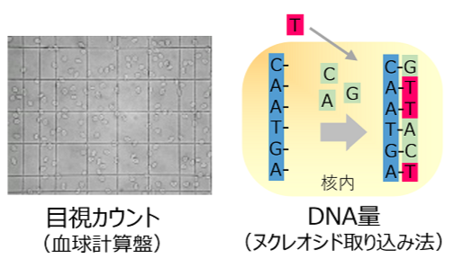
    細胞分裂に伴う細胞数を反映したもので、目視による細胞数のカウントやDNA量を測定(ヌクレオシド取り込み法など)することにより、生細胞数や細胞増殖の有無を解析します。

細胞毒性測定試薬1

  • 細胞生存能力 / Viability
    細胞全体の健康状態を測定し、間接的に細胞数、毒性を解析
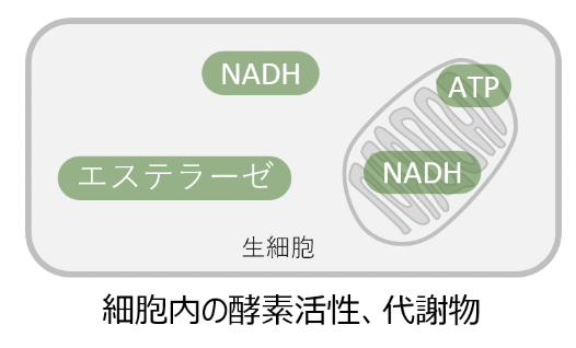
    細胞全体の健康状態を測定する指標を指しており、NADHやATPなど生細胞特有の代謝生成物の量やエステラーゼ活性など酵素活性を測定します。細胞生存能力の測定は操作が簡便であること、特殊な装置を必要としないこと、細胞増殖能力や細胞毒性を間接的に評価できることから、最も汎用されている指標となります。
  • 細胞毒性 / Cytotoxicity
    死細胞の指標を測定することで細胞に対する毒性を解析
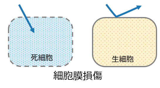
    死細胞における指標として細胞膜損傷を測定する方法が一般的に用いられており、細胞内物質の漏出や細胞膜不透過性色素での染色などにより直接的に死細胞を検出します。

細胞毒性測定試薬の使用用途

医薬品や化粧品をはじめとした、様々な化学物質の評価で使用されています。
化学物質が細胞に対して毒性を示す濃度を評価する毒性試験、化学物質が細胞に対して薬剤効果を示す濃度を評価する薬効試験などがあります。
また、動物実験の代替法としても細胞毒性試薬が利用されています。

細胞毒性測定試薬の原理

測定法には細胞増殖や毒性を直接的に解析する「細胞増殖能力」と「細胞毒性」に対し、間接的に細胞数や毒性を解析する「細胞生存能力」があります。

「細胞生存能力」測定は、MTT法やWST法と呼ばれる、還元発色試薬と生細胞中の脱水素酵素活性を利用して吸光度測定により細胞数を計測する方法で、測定の手軽さ、安全性、再現性などの点から細胞増殖試験や細胞毒性試験など幅広く利用されています。
また、「細胞毒性」測定は、細胞膜損傷により細胞外に漏れ出した酵素(Lactate Dehydrogenase:LDH)を指標に細胞毒性を測定する方法です。

細胞毒性試験について

細胞毒性測定試薬が用いられる細胞毒性検査には、検査に使用される細胞のコロニーの形成方法によりいくつかの方法があります。以下のような方法が代表的です。

  • コロニー形成試験
    コロニー形成試験は、医療機器など試料と細胞を直接接触させ、その抽出液を用いて培地にコロニーを形成させて検査をおこなう試験方法になります。
  • 直接接触試験 (コロニー形成法) 
    直接接触試験は医療機器の一部を採取し、これを培地に沈め細胞を直接播種してコロニーを形成させて試験をおこなう試験方法です。

ほかにも、「ティッシュカルチャー (TC) インサート試験 (コロニー形成法) 」や「Elution試験 (サブコンフルエント法) 」、「直接接触試験 (サブコンフルエント法) 」などの方法があります。

そして、いずれの方法においても細胞により形成されたコロニー、すなわち複数以上の細胞が集まった細胞集合体中の生細胞の割合で毒性を判断しています。

生細胞をカウントするための「細胞生存能力測定用試薬」と死細胞をカウントするための「細胞毒性測定用試薬」があります。

細胞生存能力測定用試薬

細胞生存能力測定用試薬は、細胞毒性試験においてコロニーを形成したとき生細胞のみに反応し、生細胞にのみマーキングする、もしくは生細胞との反応により生成される物質を導き出すなどして生細胞をカウントできるようにする役目をする試薬です。

生細胞のみに反応してマーキングする仕組みとしては、還元発色試薬と生細胞中の脱水素酵素活性を利用したものが代表的です。これによってマーキングされた生細胞を吸光度測定により検出し、細胞数を計測することで毒性を判断しています。

この方法は操作が簡便であり、特殊な装置を必要としないことや細胞増殖能力や細胞毒性を間接的に評価できるため、最も利用されています。

ただし、生細胞の数だけを求めた場合は細胞の全体数が減ることなくその数が生存しているのか、全体の数も減っているのかが判断できず、生細胞の脱水素酵素活性が低下していることもあります。

細胞毒性測定用試薬

生細胞の数だけを求めた場合は結果に不具合がある可能性があるため、細胞毒性測定用試薬を用いた検査も行います。細胞毒性測定用試薬を用いれば、色素の利用により死細胞の数の測定が可能です。

この色素は、死細胞において細胞膜が損傷したことで細胞外に漏れ出した酵素を指標とする死細胞のみが反応する性質があります。

「細胞生存能力測定用試薬」を用いて生細胞をカウントし、「細胞毒性測定用試薬」を用いて死細胞の数もカウントして総合的に細胞毒性を判断しています。

細胞毒性測定試薬のその他情報

細胞毒性測定試薬の種類

細胞毒性測定試薬のうち、生細胞をカウントするための細胞生存能力測定用試薬は細胞の性質や検査項目に応じた測定指標を持つものを選びます。測定指標の種類としては、以下のようなものが代表的です。

  • ミトコンドリア内脱水素酵素活性
  • 細胞内脱水素酵素活性
  • ATP量
  • エステラーゼ活性

一方の細胞毒性測定用試薬も細胞の性質や検査項目に応じた測定指標を持つものを選びます。測定指標の種類としては、以下のようなものが代表的です。

  • 細胞内酵素の漏出
  • 生細胞染色色素の漏出
  • 膜不透過性色素
  • 色素排除法

なお、これら試薬は、試薬単体として販売しているケースやキットとして販売されているケースがあります。

細胞毒性試験に関しては自社で行う場合もあれば外部委託で行う場合もあり、企業によって様々です。

参考文献

http://www.fdsc.or.jp/contract/contract_service/
https://dojindo.co.jp/products/category.cgi?bid=1&code=1631492616
https://www.ube.co.jp/usal/documents/se113_134.htm
https://dojindo.co.jp/products/contents/mtt-wst-ldh-cell-cytotoxicity-viability-proliferation.html
https://www.nikoderm.com/

本記事は細胞毒性測定試薬を製造・販売する株式会社同仁化学研究所株式会社様に監修を頂きました。

株式会社同仁化学研究所の会社概要はこちら

カテゴリー
category_usa

ELISA Kits

What Is an ELISA Kit?

An ELISA Kit is one of the immunoassay method using antibodies for quantification by ELISA (Enzyme-Linked Immunosorbent Assay).

ELISA is a method for quantifying trace amounts of biological substances using an antigen-antibody reaction.

Uses of ELISA Kits

Figure 1. Overview of ELIS

Figure 1. Overview of ELIS

ELISA kits are often used in the field of biology from the viewpoint that trace amounts of biological substances can be detected with high accuracy by antigen-antibody reaction. For example, they are used to measure blood proteins such as cytokines, chemokines, and growth factors, or in immuno-oncology to measure soluble immune checkpoint molecules to elucidate the status of cancer immunity.

In neurobiology, they is used to quantify Aβ, tau, and α-synuclein proteins that are known to cause neuropathy.

Other ELISA kits, such as phosphorylation-specific kits and immunoglobulin kits, are available, allowing you to select the ELISA kit that best suits your research and objectives.

Competitive ELISA analysis is also appropriate when measuring histamine, pesticides, dioxin, etc.

Principle of ELISA Kits

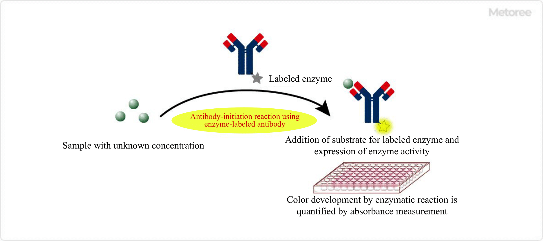
ELISA uses an antibody or an antigen that binds specifically to the substance to be measured (antigen-antibody reaction). Finally, an enzyme-labeled antibody (or antigen) is used to detect and evaluate enzyme activity by absorbance measurement.

By measuring the enzyme activity, the concentration of the enzyme in solution, the substances in the reagents involved in the antigen-antibody reaction, and the target substance can be quantified.

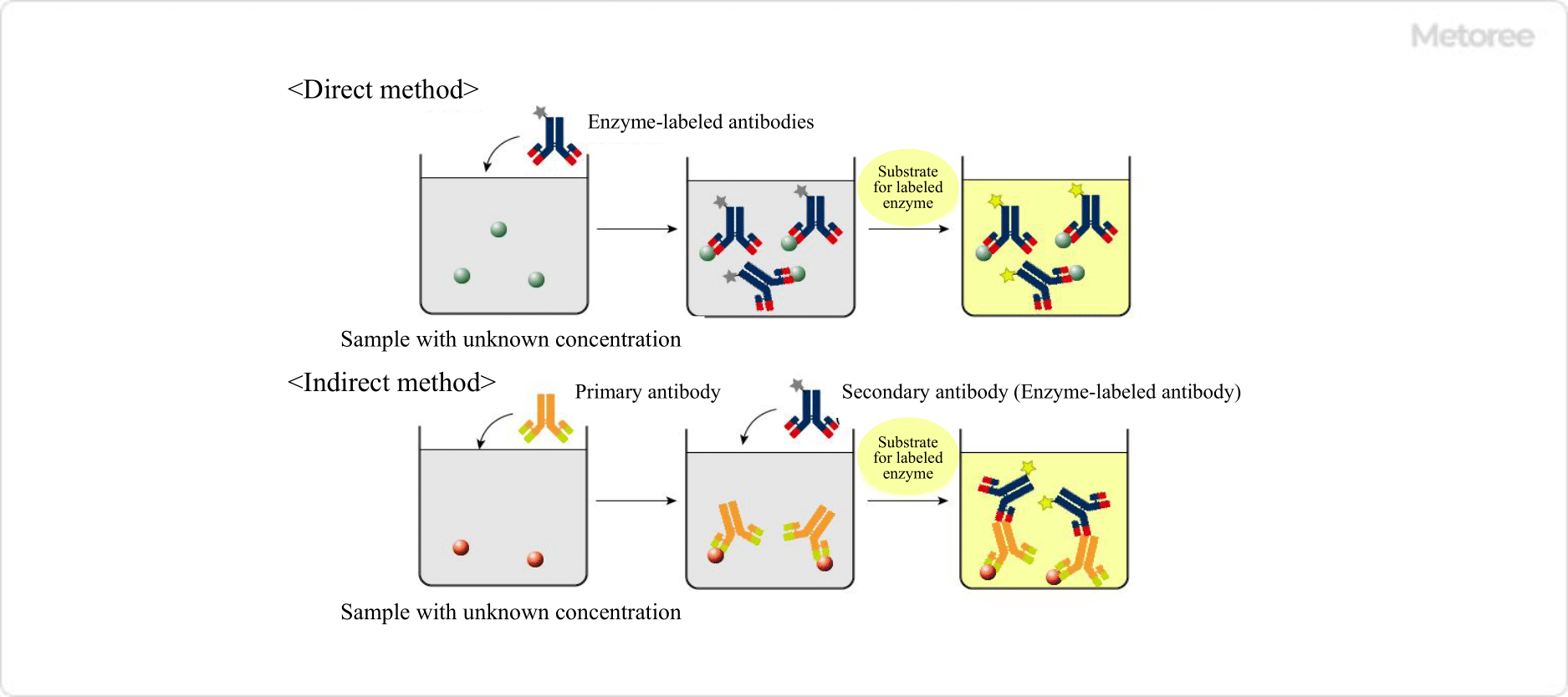
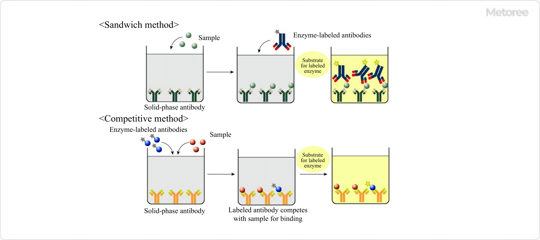
There are four main methods: direct method, indirect method, sandwich method, and competitive method.

Figure 2. Direct and indirect methods

Figure 2. Direct and indirect methods

1. Direct Method

In this method, the target antigen or antibody is solid-phased on a microplate, and the labeled antigen or antibody directly interacts with it. After the antigen or antibody is applied, the plate is washed and the enzyme activity on the microplate is detected. Since no secondary antibody is required, this method can be performed in a single step and in a short time.

2. Indirect Method

First, an antibody specific for the target antigen is applied to the solid-phase microplate. Then, the enzyme activity of the enzyme on the labeled secondary antibody is detected. This method is characterized by increased sensitivity, but requires more time than the direct method.

Figure 3. Sandwich and competitive methods

Figure 3. Sandwich and competitive methods

3. Sandwich Method

A microplate coated with an antibody that binds to the target substance in the sample is used to react with the sample as an antigen. Subsequently, the sample is reacted with another antibody labeled with an enzyme, and the excess antibody is washed off before the enzyme activity on the microplate is measured.

It is necessary to select an antibody that has a different antigen recognition site from the antibody used for solid phase and the enzyme-labeled antibody.

The advantage of the sandwich method is that the specificity of the reaction is higher than that of the direct method, resulting in higher detection accuracy.

4. Competitive Method

The competitive method can be used to measure small molecules that are difficult to detect with the sandwich method, or when there is only one binding site for the antibody.

An antibody that binds to the target substance is coated on a solid phase, and the sample is simultaneously reacted with a labeled antigen of known concentration. If the sample contains a large amount of the target substance, the absorbance decreases because there is little enzyme-labeled antigen that can bind to the antibody.

Conversely, if the sample contains less of the target substance, more of the enzyme-labeled antigen is available to bind to the antibody, resulting in an increase in absorbance.

How to Select an ELISA Kit

As mentioned above, since detection is performed using specific antigen-antibody reactions, the first prerequisite is to use a product that uses the correct combination of reagents for the sample. In addition, whether using direct, indirect, sandwich, or competitive methods, each method has their own advantages and disadvantages, so it is necessary to select the most preferable one according to the purpose of the measurement.

Solid-phase attachment to a microplate is generally by hydrophobic interaction or covalent bonding, and it is important to select the correct microplate according to the binding mode. In addition to hydrophobic and hydrophilic types, many types are available, including those processed with amino and carboxyl groups for covalent binding applications.

カテゴリー
category_usa

CT Scanners

What Is a CT Scanner?

CT ScannersA CT (Computed Tomography) Scanner is a scanner used for inspection.

There are two main types of CT Scanners: Medical CT Scanners used for imaging the human body and animals, and Industrial CT Scanners used for non-destructive testing and shipping inspection of products.

Uses of CT Scanners

CT scanners are used in the medical field to diagnose abnormalities in the brain and lungs.

In the industrial field, they are commonly used to detect the internal structure of products to measure the internal dimensions of wiring, to elucidate the internal state of forged products, to measure errors, and to detect the alignment of fibers.

When used in the medical field, X-ray output must be suppressed to avoid excessive exposure to radiation, but when used for industrial applications, X-ray output can be increased without any problem, thus enabling information to be obtained with higher precision than in medical applications.

Principle of CT Scanners

The principle of a CT scanner is similar to that of an X-ray. They consist of an X-ray irradiator, a detector, and an image processor that converts the detected data into an image.

Since each material absorbs X-rays differently (X-ray absorption coefficient), when X-rays are irradiated to an object to be examined, they penetrate at different rates of transmission depending on the material. Using this principle, we irradiate an object to be inspected with X-rays and detect the different transmission doses for each part of the object to be inspected. The general principle is to create an image by image processing based on this detection data.

The major difference between X-rays and CT scanners is that X-rays are irradiated from one direction on the specimen, while CT scanners irradiate X-rays from various directions on the specimen. For this reason, X-rays produce only flat images based on two-dimensional data, while a CT scanner uses three-dimensional data to produce a series of images of the specimen sliced in a circle at multiple locations, as well as images and movies that are composed in three dimensions.

Two physical phenomena are used in CT scanner produced scans: Compton scattering and the Photoelectric effect.

1. Compton Scattering

This occurs when X-rays collide with electrons, imparting some of the energy of the X-rays to the electrons, causing them to be blown out of their atomic orbits and reducing the energy of the X-rays.

2. Photoelectric Effect

This occurs when X-rays collide with electrons and all the energy of the X-rays is absorbed by the electrons, causing the electrons to be blown away from their atomic orbits and the X-rays to disappear.

Differences Between CT Scanners

There are two main types of CT Scanner applications: medical and industrial. The differences between them are explained from the following perspectives:

1. X-Ray Output

Medical CT scanners need to suppress X-ray output to avoid excessive exposure. On the other hand, industrial CT scanners can use relatively high X-ray output because the object to be inspected is an object, and thus can obtain highly accurate information. 

2. Configuration

Medical CT Scanner
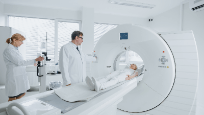
A medical CT scanner consists of a doughnut-shaped gantry in which an X-ray irradiator and a detector are placed relative to each other. The gantry has a bed-like part on which the object to be examined is placed within the ring of the gantry. The gantry rotates around the bed, and the X-ray irradiator and detector rotate around the object to be inspected.

Industrial CT Scanner
In the industrial CT scanner, the X-ray irradiator and detector are fixed relative to each other, and the part to be inspected is placed between them. By rotating the part on which the object to be inspected is placed, the object itself is rotated for inspection.

Therefore, depending on the size of the object to be inspected, industrial CT scanners can be made smaller.

Industrial CT scanners are equipped with an X-ray leakage cabinet to confine X-rays inside the device, which also makes it possible to reduce the size of the scanner.

In both medical and industrial CT scanners, there are two types: one with a single row of detectors along the X-ray transmission plane in the width direction of the object to be inspected, and the other with multiple rows of detectors along the length direction of the object to be inspected.

The one with multiple rows of detectors can acquire data for each row at a time, which makes it possible to acquire data faster than the one with only one row.

In the case of industrial CT scanners, multiple-row CT Scanners are more suitable because efficiency is more important. Medical CT scanners are also often used because the faster the examination can be completed, the less burden is placed on the patient.

Other Information on CT Scanners

1. The Relationship Between CT Scanners and Cancer

CT scans are widely used for everything from examination to diagnosis and even medical treatment, although the image of CT scans is that they are used to find cancer. Although, there is a risk of cancer from CT scans, and it is necessary to fully understand the risks when CT scans are performed.

A CT scanner is an important device in medicine, but it is not without risks of causing cancer because of the x-ray irradiation.

The risk of developing cancer from a single CT scan is considered low, and the risk of not undergoing a CT scan is much higher than the risk of undergoing a CT scan. 

2. Difference Between CT and MRI

The main difference between CT and MRI is the principle of measurement.

CT scanners form images based on differences in the transmission of X-rays through different materials, as described above, whereas MRI creates images based on the magnetic resonance of materials. CT scanners have the advantage of short acquisition times and the ease of obtaining tomographic images, and are more indicated for emergency head lesions (such as suspected hemorrhage). and the ability to image bone.

On the other hand, MRI is inferior to CT in terms of radiation exposure and differences in density between lesions and normal tissue.

Another advantage is that any tomographic image can be obtained, and images of blood vessels can be obtained without the use of contrast media. The disadvantage, on the other hand, is that those with implanted devices in the body cannot be examined.

カテゴリー
絶対に触らないでください(日本会社ニュース)

Metoreeのロゴをクリスマスバージョンに変更しました

メトリーのロゴをクリスマスバージョンに変更しました。エンジニア・研究者・購買担当者さまなど、産業用製品に関わる方の毎日が少しでも楽しくなるよう引き続き努力して参ります。


過去のロゴ

ハロウィーン