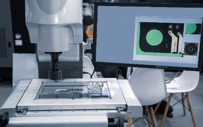
What Is a CNC Measuring System?
 A CNC measuring system is a system that uses a CCD camera to magnify the object to be measured to observe its dimensions, shape, and surface properties.
The system can move the object to be measured and the CCD camera to any desired position at high speed and with high accuracy and also perform a non-contact measurement without damaging the object to be measured. In addition, the system enables high-precision focusing by laser and image processing autofocusing, and image processing can find flaws and defects that cannot be observed with the naked eye.
Applications of CNC Measuring Systems
The CNC measuring system is used to perform continuous automatic measurement at high speed and high accuracy. The system is suitable for measurements of very small, identical patterns, such as pattern measurements of substrates and electronic components.
Because humans can become confused and fatigued when they lose track of where they have measured due to the succession of the same pattern, a CNC measuring system that always performs the same operation with high accuracy is indispensable in semiconductor production lines. It is also suitable for items that are not suited for manual measurement, as slight variations in positioning have a large impact on error when measured by humans.
Principle of CNC Measuring Systems
CNC measuring system uses a CCD camera to magnify the object to be measured in order to observe its dimensions, shape, and surface properties, and requires a system to display the image obtained by the CCD camera, to measure the dimensions and surface properties from the image, and to process the image itself.
The installation and use of a CNC measuring system requires a dedicated, temperature-controlled measurement room. This is due to the high precision of the device and the fineness of the object to be measured, which means that temperature fluctuations can have a significant impact on measurement errors.
CNC measuring systems can be operated manually, but most of the work is done through a dedicated controller or PC application software. For fast response and highly accurate positioning, the system uses a mechanism that combines a stepping motor and ball screw with a digital scale to read coordinates and perform feedback control.
Other Information on CNC Measuring Systems
1. CNC Control
CNC control is an abbreviation for “computer numerical control” and refers to the use of computers to control machine tools and other equipment. By automating machine movements such as movement direction and speed through programming, high precision and high-speed operation can be achieved.
CNC control is written using two types of programming languages, G code and M code, in which G code describes the conditions and sequence of machining and movements, such as positioning, while M code serves as a supplement to G code.
2. CCD Camera Configuration
A CCD camera, which is also used in the CNC image recognition system, consists of a microlens, a color filter, and a photodiode, each of which has the following functions.
Microlens
Microlenses are responsible for focusing the light that has passed through the lenses to deliver it to the photodiode efficiently.
Color Filter
Color filters break down light into RGB (red, green, and blue) or CMY (cyan, magenta, and yellow) and deliver the light to the photodiode.
Photodiode
When light is received, photoelectric conversion is performed to generate an electric charge, which is transferred vertically and horizontally. The transferred charge is converted to a voltage at the output of the CCD, and an image is output for each pixel.
Since R, G, and B are assigned to each photodiode, the resolution is reduced to about 1/3 of the original CCD pixel count. The image processing engine complements the image to produce an image with the original pixel count. The RAW format saves the data extracted from the photodiode without any composite processing.