カテゴリー
category_usa

Recessed Handle

What Is a Recessed Handle?

A recessed handle, commonly used in devices and fittings like machinery and doors, is a type of handle that is embedded into the side of a device or fixture, creating a sunken area for grip. These handles typically have a lower load-bearing capacity and are designed primarily for operating and carrying lighter objects.

Applications of Recessed Handles

Recessed handles are frequently installed on equipment and fixtures to aid in operation and transportation. They are characterized by their inset design, which doesn’t protrude from the surface, making them ideal for space-saving installations. They are used in various settings, including on doors, machinery, drawers, and storage solutions. Folding handles, which are stored within a recessed base and lifted for use, are also a popular type of recessed handle, particularly for wall and floor storage solutions.

Choosing the Right Recessed Handle

When selecting a recessed handle, factors such as material, size, shape, and additional features like locking mechanisms should be considered. The choice of material—ranging from metals like aluminum, steel, and stainless steel to plastics and resins—depends on aesthetic preference and load-bearing requirements. Plastic handles are often chosen for drawers and cupboards due to their low cost and ease of processing. In contrast, foldable handles, which can be extended from a recessed base, are more suitable for transporting heavier objects.

Recessed handles are also available with various functionalities, including locking mechanisms for drawer safety and antibacterial coatings for hygiene in communal environments.
カテゴリー
category_usa

Telecentric Lens

What Is a Telecentric Lens?

Color-Changing at High Temperatures

A telecentric lens is a special type of lens designed with an optical axis that runs parallel to the principal ray. This design allows for capturing images without angular view or parallax error. It’s particularly effective for objects with uneven surfaces or depth, ensuring constant magnification, ideal for precision processing.

These lenses are adept at producing distortion-free images, maintaining consistency across the center and edges. They are commonly used for inspecting minute surface details like scratches and dust on reflective objects, including glass.

Applications of Telecentric Lenses

Telecentric lenses have diverse applications, such as in the inspection of three-dimensional objects. They prevent the distortion typical in images captured with normal lenses, ensuring an accurate representation of the object. This makes them valuable for detecting dust and scratches, as their design helps avoid errors due to parallax, enhancing the visibility of such imperfections.

Types and Principles of Telecentric Lenses

  • Object-side Telecentric Lenses: These lenses have parallel main rays on the object side, enabling accurate measurement without size alteration due to object movement. They are relatively compact.
  • Image-side Telecentric Lenses: Positioned on the image side, these lenses maintain uniform brightness on the image plane, although the image size may vary with object movement.
  • Bilateral Telecentric Lenses: Utilizing two lenses, these offer parallel main rays on both object and image sides, providing enhanced accuracy.

Limitations of Telecentric Lenses

Telecentric lenses tend to have a large diameter, dictated by the CCD/CMOS element size. While suitable for small objects, their large size can be a constraint in space-limited applications. They are also not ideal for systems that require depth information, like VR and AR, due to their inability to capture depth via binocular parallax.

Calibration and Performance of Telecentric Lenses

While telecentric lenses minimize errors caused by the angle of view, they are not free from distortion. Common optical distortion is around ±0.5%, which is lower than typical lenses (±20% or more). It’s crucial to consider this in applications where even minor distortion impacts performance, requiring additional software or hardware correction.

カテゴリー
category_usa

Thermo Marker

What Is a Thermo Marker?

Color-Changing at High Temperatures

A thermo marker is a unique marker that changes color permanently when exposed to high temperatures, visually indicating areas that have become hot or were exposed to heat.

Applications in Screw Tightness Monitoring

Thermo markers can be used to draw on screw heads, serving as a visual temperature indicator and to check screw tightness. However, they are not suitable for outdoor use due to ultraviolet light sensitivity.

Common Uses of Thermo Markers

Monitoring High-Temperature Equipment

Thermo markers are applied to screws and components of boilers, piping, and electrical equipment prone to high temperatures. They are preferred over thermal seals due to their adhesive reliability.

Loose Screw Detection

By marking a tightened screw with a thermo marker, any shift in the line indicates loosening, providing a simple way to monitor screw integrity during operation.

Characteristics of Thermo Markers

Permanent Color Change with Temperature

These oil-based markers change from red to yellow at temperatures ranging from 105 °F to 175 °F. Once changed, the color remains altered even after cooling, except under extreme cold below -13 °F. This permanent change helps identify overheating areas or steam leaks and serves as a safety alert. However, the markers are not designed for very low temperatures, where they may revert to the original color.

Limited Weather Resistance and Adhesion

Thermo markers lack strong weather resistance and may fade in outdoor environments. They also do not adhere well to certain materials like rubber, packing tape, and Teflon. It’s advisable to test the marker on the intended surface before field application, as the ink is more prone to peeling compared to regular markers.

カテゴリー
category_usa

Detector Tube

What Is a Detector Tube?

Detector TubesSpecific Detector Tubes for Each Gas Type

Detector tubes are tools for measuring gas concentrations, such as harmful hydrogen sulfide or flammable hydrogen. Each type of gas requires a dedicated detector tube.

Variety of Detector Tubes for Short and Long-Term Measurement

Detector tubes are available for measuring gas concentrations over short or extended periods. Their ease of use involves drawing the gas through a piston.

Applications of Detector Tubes

Environmental Monitoring in Manufacturing and Construction

Detector tubes, simple to operate, are widely used in manufacturing and construction for environment monitoring and legal compliance, especially for detecting flammable gases to prevent explosions and ignitions.

Pollution Control and Research

These tubes are also utilized for controlling pollution by measuring air contaminants and analyzing gases in chemical reactions for research purposes.

How Detector Tubes Work

Gas Concentration Measurement Through Reaction

Detector tubes contain a reactive substance that changes color upon reacting with the target gas, providing a visual quantification. Each tube type has specific quantitation and detection limits.

Applications in Hazardous Environments

In high-risk or oxygen-deficient areas, remote sampling tubes are used to measure gas concentrations safely.

Specific Tubes for Specific Compounds

Each detector tube is specific to a particular compound and has an expiration date. It’s crucial to check this before use and to sample at multiple points due to potential gas distribution variances.

Kitagawa Gas Detector Tubes

Kitagawa gas detector tubes consist of a detector and a gas sampler, used since 1947, primarily for hydrogen sulfide detection. The color change in the detector agent upon reaction indicates the gas concentration.

This method allows for rapid onsite measurement of flammable gases, preventing potential fires or explosions. The tubes are prepared with a chip cutter, inserted into the sampler, and then the discolored boundary is read for concentration assessment.

Detection Conditions for Various Gases

For ammonia gas, the measurement range is less than 30 ppm and the detection limit is about 0.2 ppm when the gas is aspirated once (100 ml). The presence of ammonia causes a neutralization reaction (2NH3 + H2SO4 → (NH4)2SO4) with sulfuric acid, which changes the indicator from pink to yellow.

The measurement range of oxygen is 3-6%, with a detection limit of about 2% for a single aspiration (100 ml). When oxygen is present, the reaction with titanium trichloride (O2 + 4TiCl3 (black) + 6H2O → 4TiO2 (white) + 12HCl) produces titanium oxide, which causes the indicator to change from black to white.

Carbon dioxide has a measurement range of 100 to 2000 ppm with a detection limit of about 20 ppm for a single aspiration (100 ml). The presence of carbon dioxide causes a neutralization reaction (CO2 + 2KOH → K2CO3 + H2O) with potassium hydroxide, which changes the indicator from light red to orange.

カテゴリー
category_usa

Small Pan Head Screw

What Is a Small Pan Head Screw?

Small Pan Head ScrewsSmall pan head screws, including pan head machine screws and cross-recessed types, are named for their overturned pot-like head shape. These screws are typically used with female threads or nuts, featuring a flat threaded end.
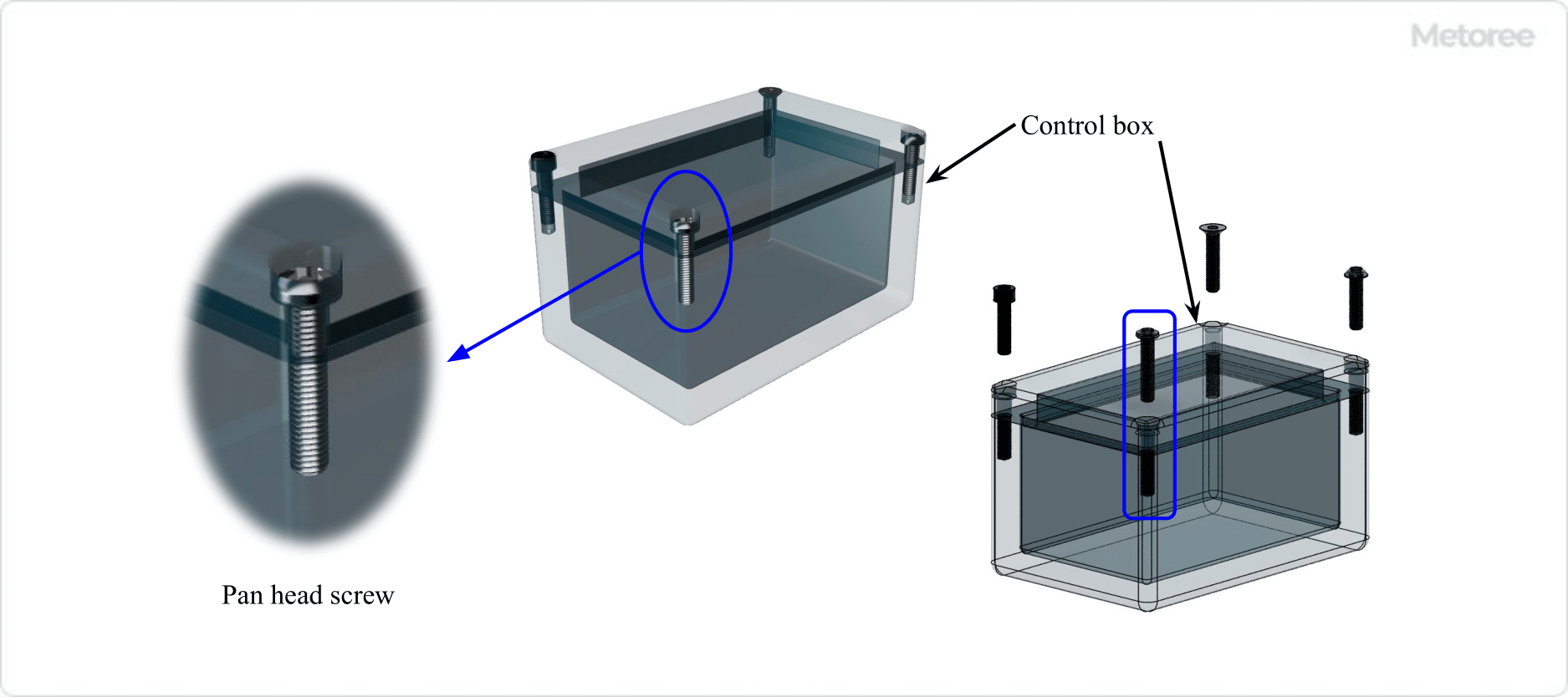
Commonly paired with metal washers, small pan head screws are versatile in applications and sometimes referred to as “cross-hole small pan head screws.”

The standard for these screws is ANSI/ASME B 18.6.3, covering machine screws, tapping screws, and metallic drive screws.

Uses of Small Pan Head Screws

Figure 1. Example of pan head screw use (1)

Small pan head screws are utilized in a diverse range of sectors, including industrial machinery, home appliances, and toys. They differ from bolts in head shape and size, with screws typically ranging from M2 to M8 sizes.

Principle of Small Pan Head Screws

Figure 3. Hole shape of pan-head screw head

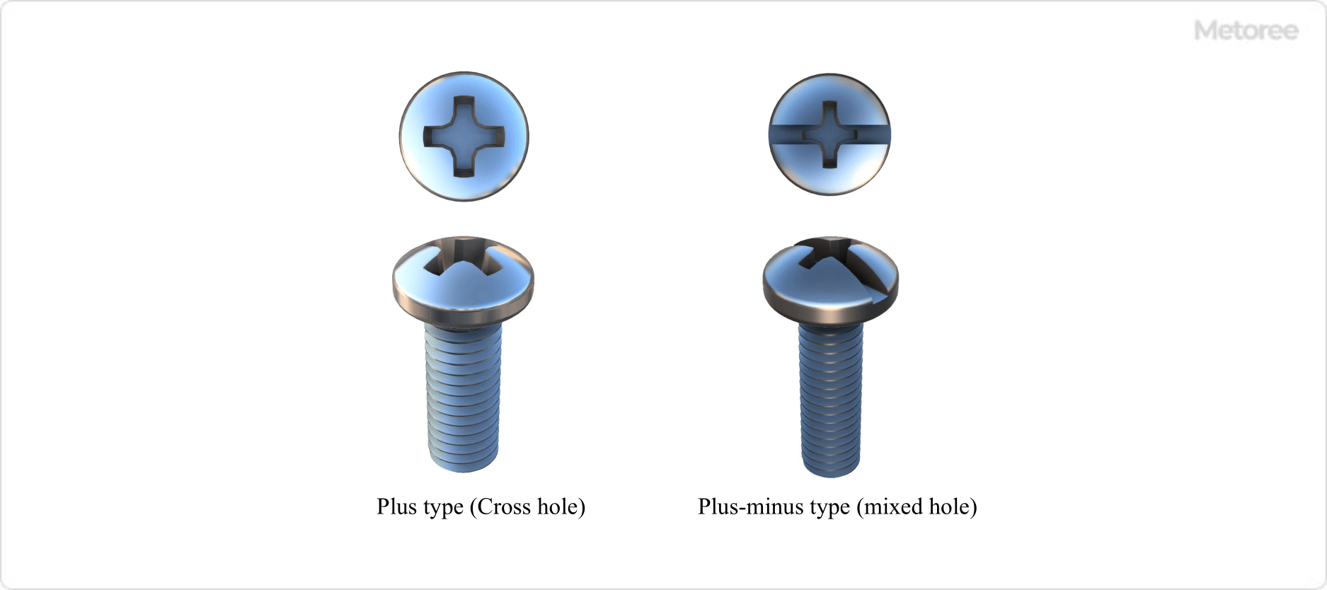
Small pan head screws are fastened by inserting a Phillips screwdriver into their cross-shaped hole. This differs from hexagonal bolts which require a wrench. Their deeper cross-hole head allows for stronger tightening force compared to countersunk screws.

These screws come in two types of screwdriver insertion holes: the cross-shaped “plus” and the mixed “plus/minus” types, and their length is measured excluding the head height.

Other Information on Small Pan Head Screws

1. Main Materials and Surface Treatment

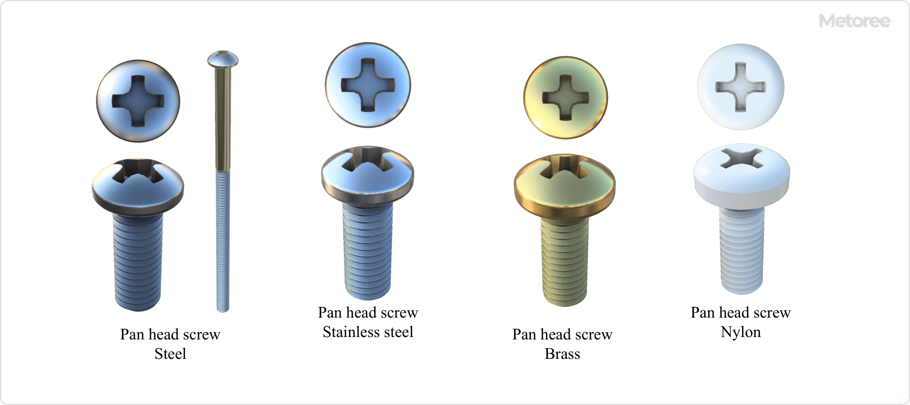
Figure 4. Examples by pan head screw material

Materials range from steel and brass to aluminum and titanium, with plastics like polycarbonate and nylon also used. Surface treatments such as electroplating and anodizing are applied for corrosion resistance.

2. Proper Use and Tightening Tools

Proper use involves ensuring the tightening force is within allowable limits to prevent damage. For tightening, a Phillips screwdriver or other suitable tools should be used, matching the size of the screw head’s cross-hole.

3. Loosening Prevention

Adhesives or specially treated bolts can be used to prevent loosening of small pan head screws.

カテゴリー
category_usa

Straight Core Pin

What Is a Straight Core Pin?

A straight core pin is a specialized metal fitting used in the plastic injection molding process to create precise, straight features in molded products. It allows for the incorporation of straight holes or protrusions in a mold, which is challenging to achieve through standard cutting methods due to complexity and precision requirements. Straight core pins are vital for creating straight holes, while other shapes of core pins, like tapered ones, are used for different configurations.

Uses of Straight Core Pins

These pins are primarily used to form holes or slots in plastic products for various functional needs such as rotary shafts, bearing holes, and threaded holes. They also serve in reducing product weight, creating venting holes, and aiding in gas release during the molding process. Straight core pins are particularly beneficial in molding intricate components like electronic parts, where they facilitate efficient gas venting without altering the minute geometrical features.

Principle of Straight Core Pins

In molding applications, straight core pins are installed in the mold’s core or cavity. Their effectiveness depends on the mold’s design and the pin’s placement. During resin injection, the pins need to withstand the pressure without bending or misaligning. For through-hole designs, the hole’s length should typically be less than twice the pin’s diameter to maintain stability. In scenarios where extended hole lengths are needed, additional support on either side of the mold can be provided.

While hole creation with straight core pins is often necessary for the product’s function, it can present challenges like reduced structural strength, the potential for weld lines or other surface defects, and increased mold-making costs. Therefore, careful design considerations, including appropriate hole spacing and structure, are crucial to mitigate these issues and ensure product quality.

カテゴリー
category_usa

Round Countersunk Screw

What Is a Round Countersunk Screw?

Round Countersunk Screws

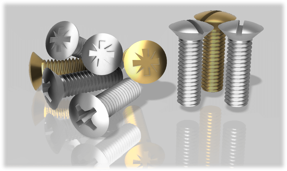
Round countersunk head screws, also known as oval head screws, feature a tapered conical shape that narrows toward the screw side, resembling a dish from the side. Unlike flat head screws, the top of a round countersunk screw head is rounded, offering a sleek appearance. They are screws with a small nominal head diameter and usually have a slotted or cross-holed drive.

The terms “round countersunk small screws” are commonly used to refer to this type of screw.

Uses of Round Countersunk Screws

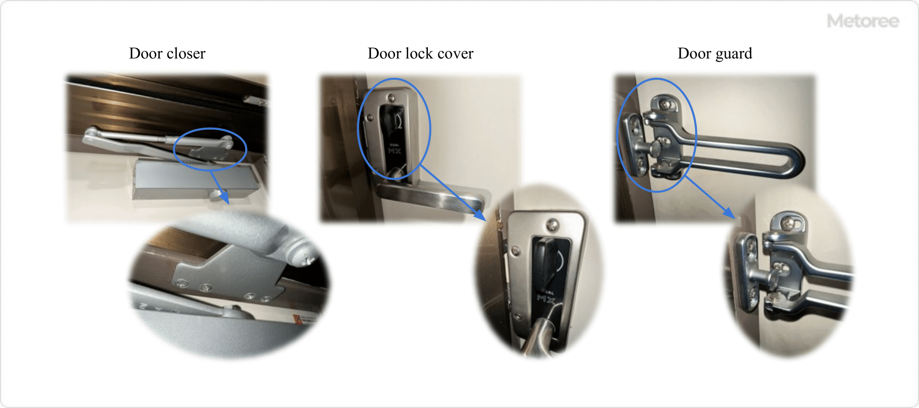
Figure 1. Example of Using a Small Round Countersunk Screw

Figure 1. Example of Using a Small Round Countersunk Screw

Round countersunk screws are primarily used in applications requiring female threads, where a tapered counterbore is drilled into the workpiece slightly larger than the screw’s tapered head. This allows the rounded part of the screw head to protrude slightly above the surface, providing a more aesthetic finish than flat head screws, especially in visible areas such as door closers, lock covers, and guards.

Principle of Round Countersunk Screws

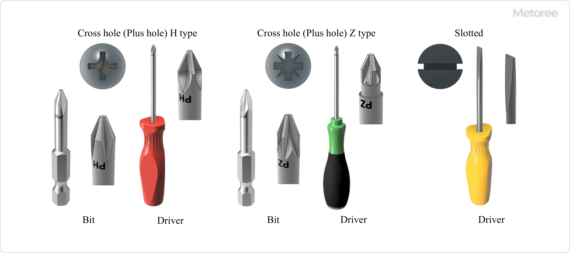
Similar to other countersunk screws, round countersunk screws are designed for direct insertion into tapped female threads without the need for a nut. They are tightened using a Phillips or flat-blade screwdriver inserted into the screw head’s cross or slot. The length of these screws includes the head, differing from bolts where the length is measured excluding the head.

Types of Round Countersunk Screws

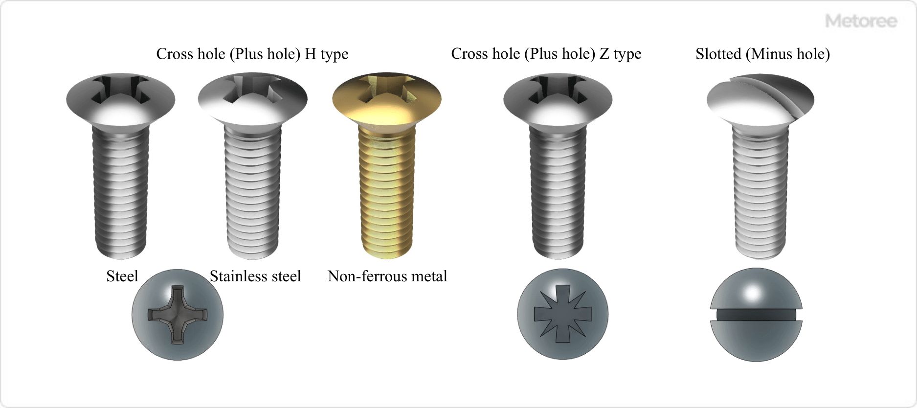
Figure 2. Types, Materials, and Shapes of Small Round Countersunk Screws

Figure 2. Types, Materials, and Shapes of Small Round Countersunk Screws

Classification of round countersunk screws includes variations in head hole shapes and materials.

1. Classification by Hole Shape of Countersunk Head

Head hole shapes include Cross (Phillips) and Suriwari (Minus), each requiring specific tools for tightening. The H (Phillips) and Z (Pozidriv) shapes differ, with Z types being less prone to cam out. The Suriwari shape, a single straight groove, uses a flat-blade screwdriver for tightening.

Figure 3. Hole and Tool Geometry of the Head of a Small Round Countersunk Screw

Figure 3. Hole and Tool Geometry of the Head of a Small Round Countersunk Screw

2. Classification by Material (Strength Classification)

Materials for round countersunk screws include steel, stainless steel, and nonferrous metals, classified by strength and governed by various standards.

Other Information on Round Countersunk Screws

  • Standards such as ISO 7047 apply to round countersunk screws. Compatibility with standards is crucial for ensuring correct thread pitch and head diameter.
  • Sizes range from M2 to M8, with recommended lengths from 4 to 60 mm.
カテゴリー
category_es

Interruptor de Hoja

カテゴリー
category_usa

PWM Controller

What Is a PWM Controller?

PWM Controllers

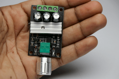
A PWM (pulse width modulation) controller is a device that adjusts the pulse width of current or voltage, maintaining a constant frequency. This modulation alters the duty cycle to control the duration of the ‘on’ and ‘off’ states of the pulses. The duty cycle is calculated by dividing the pulse width by the total cycle time. Semiconductor devices are utilized for PWM switching.

Uses of PWM Controllers

PWM controllers regulate motor speeds across various types, including AC, DC, and synchronous motors. In the manufacturing industry, AC motors often incorporate feedback from speed detectors, like pulse generators, to adjust the motor’s speed accurately. The feedback signal is processed to determine the precise voltage required, which is then applied using the PWM controller integrated into the board.

Principles of PWM Controllers

PWM controllers generate output pulses by modulating a sine wave (the control source) with a sawtooth wave (carrier) using a comparator made of operational amplifiers. A pulse is created when the sine wave exceeds the sawtooth wave and is turned off when it is less. This process produces pulses that are denser at higher sine wave values and sparser at lower ones. Switching devices, such as transistors and thyristors, are employed for this on/off mechanism, functioning through signals received at their gates.

Structure of PWM Controllers

The structure of a PWM controller includes three primary components: a data register, a counter, and a comparator. Each period and duty register is associated with a specific comparator, whose outputs connect to the set and reset pins of a flip-flop circuit. This configuration allows for precise control of the PWM signal’s cycle width and pulse width, enabling the output of a consistent PWM signal.

Other Information on PWM Controllers

Precautions When Using a PWM Controller

PWM control benefits from reduced stress on transistors and currents by only allowing current flow during the ‘on’ phase of power pulses. However, a drawback is the potential for a self-induction effect caused by the motor’s coil inductance when PWM control is off, leading to significant electromagnetic interference and potential damage. Implementing flywheel diodes in the circuit mitigates these issues by redirecting reverse power back to the motor.

カテゴリー
category_usa

Triangle Corner Brace

What Is a Triangle Corner Brace?

Triangle Corner Braces

A triangle corner brace is a metal bracket used for reinforcing joints in buildings, furniture, and various other structures. These braces are particularly effective in strengthening weak joints, thereby improving overall safety and durability. They are commonly employed to secure furniture like bookshelves to walls, offering additional stability, especially in earthquake-prone areas.

Uses of Triangle Corner Braces

Triangle corner braces are versatile and can be used in a myriad of products, including furniture, appliances, industrial equipment, and even automotive construction. They are particularly valuable in reinforcing wooden structures like furniture and building frames. By fastening these braces to right-angled wood joints with nails or screws, the strength and stability of the joint are significantly enhanced. In Japan, for instance, triangle corner braces are widely used to anchor bookshelves and lockers to walls as a precaution against earthquakes.

Principle of Triangle Corner Braces

As a specific type of bracket, triangle corner braces are right-angled metal fittings designed with multiple holes for easy attachment using screws or bolts. Available in various materials, the choice of material for a brace depends on its intended use and the environmental conditions where it will be installed.

Steel, often chosen for its strength, is usually plated or painted to prevent corrosion. Surface treatments not only enhance corrosion resistance but also improve the aesthetic appeal, making them suitable for a range of applications. For high-end furniture, materials like copper and brass are popular, though they require careful consideration due to their susceptibility to corrosion, especially in humid or seaside environments. Zinc alloys are another option but, like steel, they are best used with surface treatments for improved durability.