カテゴリー
category_usa

Potentiostat

What Is a Potentiostat?

A potentiostat is a device that controls electric potential and current and measures electric potential.

In a three-electrode system consisting of a working electrode, a counter electrode, and a reference electrode in an electrolyte, it controls the voltage between the working electrode and the reference electrode and measures the current flowing between the working electrode and the counter electrode. It is used in electrochemical measurements and is often used in conjunction with galvanostats and function generators.

While galvanostats accurately control the current flowing through the electrode and arbitrarily regulate the electrochemical rate, potentiostats control the potential of the electrode and measure the current flowing through the electrode at that time. Potentiostats are used to measure the current flowing through an electrode.

Uses of Potentiostats

Potentiostats are mainly used for electrochemical measurements. In practice, potentiostats are rarely used alone but are most often used in combination with galvanostats and function generators.

Potentiostats alone can only perform constant voltage control, but when combined with these devices, they can perform voltage sweep operations and pulse outputs, and their response can be measured to gain a deeper understanding of the electrochemical characteristics of an object.

Principle of Potentiostats

The key to the potentiostat’s principle is its negative feedback control using an operational amplifier.

The operational amplifier is represented by the circuit symbol shown in Figure 1 and has the following two characteristics:

  1. Very large internal impedance
  2. The voltage at the positive and negative input terminals can be regarded as the same (VIN1=VIN2)

3020_Potentiostats_ポテンショスタット-1.png

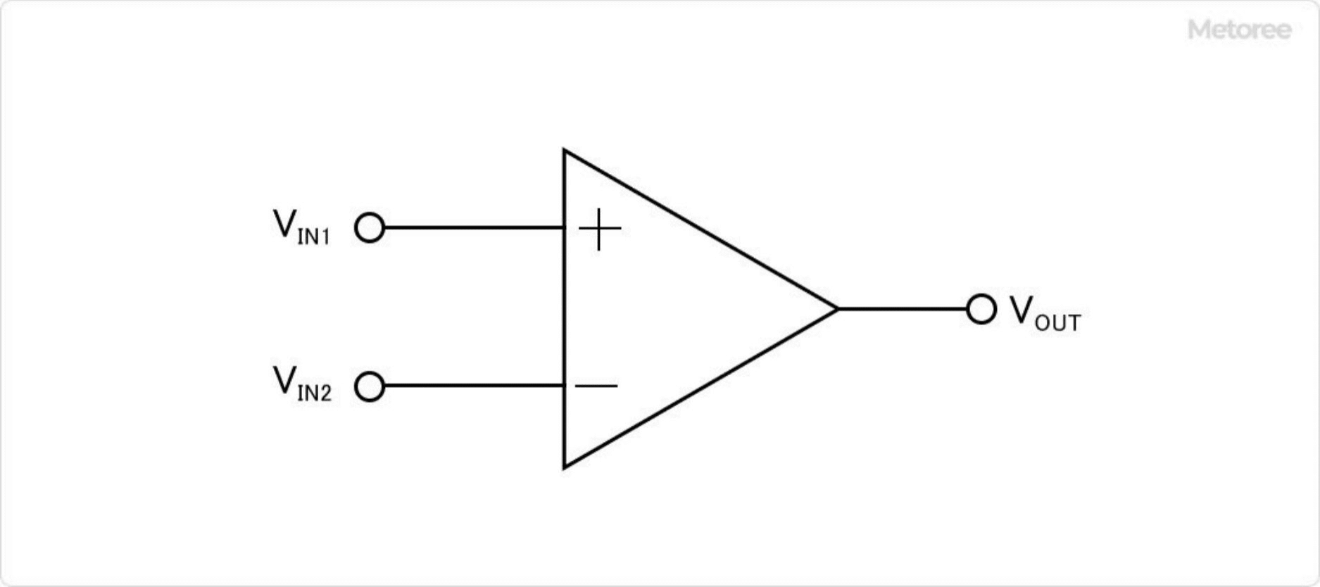
Figure 1. Circuit symbols for operational amplifiers

The following major functions of the potentiostats are achieved by the circuit using an operational amplifier:

  • Prevents current flow to the reference pole
  • Controls the potential of the working electrode with respect to the reference electrode
  • Measures the current flowing between the working electrode and the counter electrode

The high internal impedance prevents current from flowing to the reference pole, and since the voltage at the positive and negative ends is the same, the set voltage can be used as the voltage at the reference pole as it is.

Since the operational amplifier outputs a voltage corresponding to the flowing current, the current can be measured.

Other Information on Potentiostats

1. What Is Electrochemical Measurement?

3020_Potentiostats_ポテンショスタット-2.png

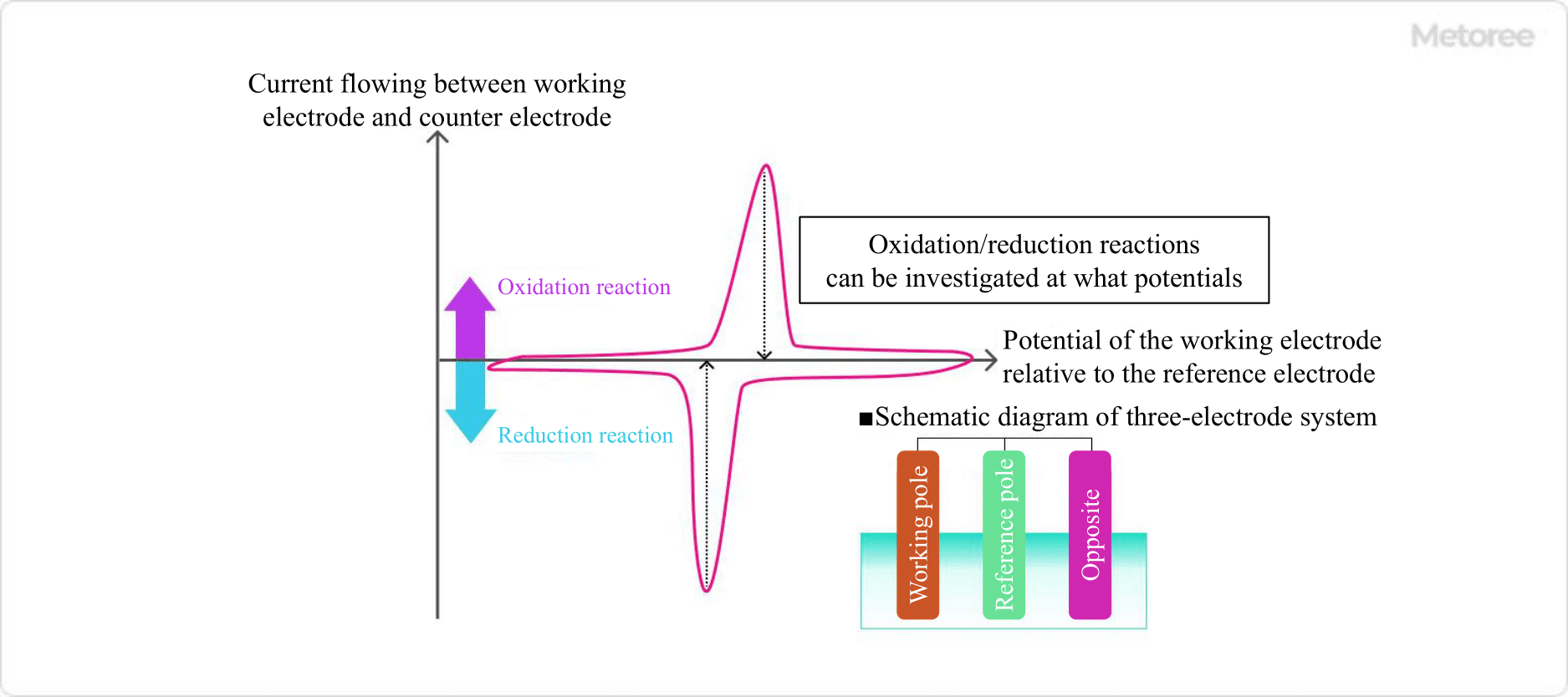
Figure 2. Example of voltammogram

Electrochemical measurement is a measurement technique in which an electrical signal is applied to a specific sample from a power source or another circuit to induce a chemical reaction, and the response signal is used to evaluate the chemical reaction occurring inside.

A common example is the electrolysis of water. By inserting electrodes connected to potentiostats into water and applying electrical energy from an external circuit, the electrolysis reaction of water can be promoted or reversed on the working electrode. This technique can be utilized in the development of catalysts that promote the electrolysis of water.

In the voltammogram measurement, a computer is used to convert the controlled electrode potential from a digital signal to an analog signal, and the electrolytic current measured by the potentiostats is digitized and read by the computer. In this way, it is possible to determine how much current flowed in relation to the voltage change.

From the voltammogram, it is possible to determine what kind of oxidation/reduction reaction is taking place at the working electrode at each potential.

2. Reasons for Using a Three-Electrode System

3020_Potentiostats_ポテンショスタット-3.png

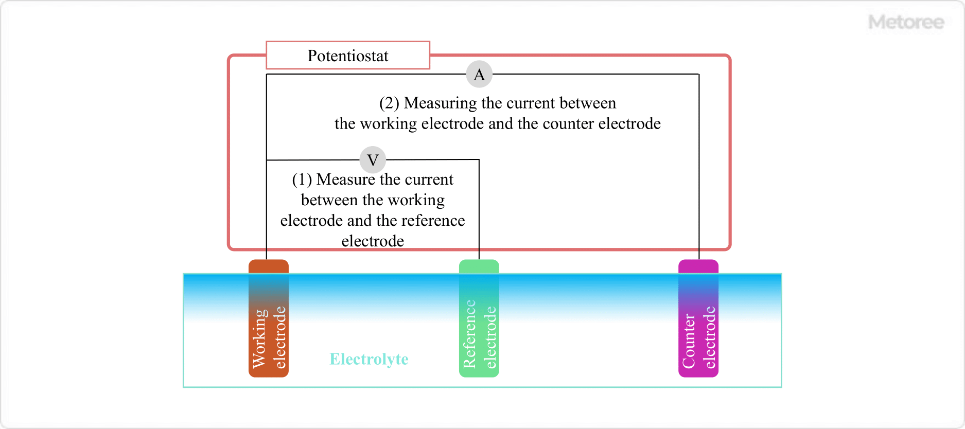
Figure 3. Schematic diagram of potentiostat and three-electrode system

In electrochemical measurements, it is necessary to accurately determine the potential of reactions occurring at the electrodes. 2-electrode electrochemical measurements cannot accurately measure the potential due to the phenomenon of polarization, which occurs when current flows through both the working and counter electrodes. Polarization refers to a shift in electrode potential due to current flow in the circuit.

Therefore, a reference electrode is added as a third electrode to form a three-electrode system consisting of an action electrode, a counter electrode, and a reference electrode. No current flows through the reference electrode, and by measuring the potential difference between the working electrode and the reference electrode, the potential of the working electrode can be accurately measured.

カテゴリー
category_usa

Post Processor

What Is a Post Processor?

A Post Processor converts the cutting path generated by CAM into an NC program suitable for the configuration of the controller and machine tool.

In Latin, Post means “after” and Processor means “something that processes.” A Post Processor is a post-processor of the main processor.

Typically, company-specific NC machines and CAM systems have corresponding conversion libraries. A typical Post Processor is required for each control or NC machine tool. However, some post processors can register controller- or NC machine tool-specific specifications in parameter form and switch to the NC data corresponding to each machine with a simple operation.

Usage of Post Processor

3D-CAD data is becoming increasingly popular in the manufacturing field to facilitate product data linkage across departments and advance verification in the upstream process. However, in parts machining, multitasking machines are becoming more common in order to respond to diversifying production forms such as process integration and part shapes, and easy conversion to NC programs using 3D-CAM is required. A Post Processor is required to perform this conversion accurately.

Principle of Post Processor

Post Processor performs post-processing using dedicated post-processing applications suitable for various CAM systems, reverse processing the target NC data, and converting it to NC data for other machines by utilizing past NC data assets.

Post Processor supports input of any of the various APT sources, as well as CL data, and can be configured for each machine by setting the specifications of the NC machine tool and control unit.

Machining information such as machining time, machining start coordinates, machining end coordinates, and NC conversion results can be output. In general, the contents of Post Processors are not disclosed.

Types of Post Processors

Major machine tools for which Post Processors are used include 3-axis to 5-axis machining, NC lathes, punch-cut machines, wire-cut machines, laser-cut machines, and multi-tasking lathes.

Examples of controller manufacturers include Yamazaki Mazak, Ohm, Okuma, Fanuc, etc. Specific examples of CAM systems include AUTON, CATIA V4/V5, DELCAM, CIMATRON, Pro-E, I-DEAS, MasterCAM, SURFCAM Unigraphics, VX, WorkNC, etc.

How to Choose a Post Processor

Although a typical Post Processor can be used with the standard system installed at the time of shipment, there are cases where the standard system may not be sufficient for a given machining task. Customization of the Post Processor is necessary to accommodate the desired processing.

However, customizing the Post Processor requires advanced knowledge of the language and control panel, and is highly difficult. Care should be taken when customizing.

Post Processor Structure

General CAM software consists of two types of processors: a Main Processor, which calculates tool path data on a model coordinate system such as CAD, and a Post Processor, which converts CL data into an appropriate NC program.

The main CAM Post Processor converts CL data calculated on the model coordinate system to the machine coordinate system, considering the structure of the machine tool to be used and the specifications of the NC device. It then adds command codes such as feed rate, spindle speed, and macros, and can output appropriate NC data.

Commercially available CAM software clearly distinguishes between Main Processor and Post Processor. Post Processors had to be prepared for each combination of machine tool and CAM software owned by the user. Nowadays, there are general-purpose Post Processors that can be used for any combination of machine tool and CAM software, once the parameters are set.

カテゴリー
category_usa

Post Pallet

What Is a Post Pallet?

Post Pallets

A post pallet is synonymous with a folding pallet and is a simple rack that can be stacked.

There are two types: one with posts fixed at the four corners that can be folded for compactness, and one with detachable posts that can be removed and stacked for compactness. They can handle everything from storage to transportation with cargo loaded. They can be nested when not needed, so they require little space when not in use.

Since products can be loaded directly on the pallet, the pallet can be used in any shape, making it ideal for long materials such as architectural hardware (doors, sashes) and rolled items (textiles, films).

Uses of Post Pallets

Post Pallets are pallets that combine the functions of both a pallet and a rack. Since they can be moved while loaded, they can be used for everything from storage to transportation. By stacking them in multiple layers, products can be loaded and stored efficiently using space, and when not in use, the pallets can be reduced to a quarter of their original size by folding (or removing) the support columns. In addition, post pallets can be stacked on top of each other for compact storage.

The pallets can be used for any shape of cargo, and are especially suitable for long materials.

Features of Post Pallets

Post pallets have posts attached to their four corners. They are made of metal and often have a basic load capacity of 1000 kg (2,200 lb). Many products are durable, robust, and weather-resistant.

There are removable and fixed types of posts, and when not in use, they are stored by nesting (refers to a storage method in which another structure is inserted into some structure). The removable type is more neatly stacked on top of each other, while the fixed type eliminates the process of removing and installing the posts. This saves storage space and reduces delivery return costs.

Nesting racks are similar in function to post pallets. Nesting racks are useful when products are stored on regular pallets. However, nesting racks are less efficient when loading trucks and the advantage of post pallets is that they can handle everything from storage to transportation without moving goods.

カテゴリー
category_usa

Ball Mill

What Is a Ball Mill?

Ball Mills

A ball mill is a type of milling equipment that performs milling by rotating balls of alumina or other material in a cylindrical container as the milling medium. In a broad sense, there are the vibration ball mill that vibrates a container, and planetary ball mill that rotates the container, but generally speaking, ball mills that rotate containers are more common.

The grinding balls (20 to 100 mm in diameter) and raw materials are placed in this device, which can rotate horizontally, and the raw materials are finely ground by collision with the grinding balls, impact between the grinding balls and the inner surface, and frictional crushing.

Bead mills are also used to pulverize raw materials. The grinding power of a ball mill is determined by the free fall of the grinding balls. In contrast, in a bead mill, strong impact force is applied by centrifugal force by a stirring device. Another feature of bead mills is that the bead diameter is smaller than that of a ball mill, at 2 mm or less. Due to the difference in milling energy and other characteristics, these types of equipment are used differently in the field.

Uses of Ball Mills

Ball mills are used in a wide variety of fields, such as ore, coal, cement, pharmaceuticals, ceramics, and metals, because of their simple structure and ease of scale-up. Some examples are listed below.

  • Titanium dioxide (applications: pigments, colorants, photocatalysts, offset printing, cosmetics)
  • Carbon black rubber (applications: product reinforcement, paints, additives for magnetic recording media, battery materials)
  • Barium titanate (Applications: ceramic capacitors, laminated capacitors, and other electronic components)
  • Alumina (Applications: ceramics and abrasives)
  • Resin (Applications: some battery parts and use in general-purpose plastics)

Principle of Ball Mills

The optimum rotation speed N of ball mills depends on the size of the grinding media, grinding method (dry or wet), presence of lifters, and size of the mill. In general, ball mill specifications are expressed as the ratio of the critical speed Nc to the optimum speed N (N / Nc). The “critical rotation speed Nc” shown here is the minimum speed at which particles remain crimped to the far east inner wall due to centrifugal force. When calculating the rotational speed when the milling balls are 30 mm in diameter, it is common to obtain values of 75% for the dry type and 65% for the wet type.

The ratio of powder, balls, and space in the vessel also affects the milling process. Generally, each should be about 1/3 of the volume, but in practice, conditions should be changed depending on the sample and purpose (processing time and batch volume).

In dry milling, the raw material and balls are placed in the mill. The advantage of this simple structure is that impurities are unlikely to be mixed in. In wet milling, water or an organic solvent is added in addition to the raw materials and grinding balls. This method is suitable for blending and mixing raw materials. An air purge mechanism is standard to improve the discharge efficiency of the milled products. Special containers are sometimes used for ball mills. This is used for the grinding of materials that are explosive or oxidizable during the grinding process.

How to Select Ball Mills

There are two main types of ball mill containers: ceramic and metal. Metal is used for large production applications, but if there are concerns about metal contamination or corrosion, the inner walls must be lined with rubber or urethane. This increases the cost and may be difficult to manufacture depending on the size. Balls are made of the same material as the container. The larger the density of the material, the stronger the crushing force, and the smaller the ball diameter, the more contact points there are, thus increasing the crushing capacity. However, some materials are more prone to wear than others, so care must be taken in selecting the right material.

カテゴリー
category_usa

Glue Gun

What Is a Glue Gun?

Glue Guns

A glue gun is a device used for bonding by heating solid resin to a liquid state and then cooling it to solidify again. This method is known for being non-flammable and eco-friendly, as it does not use volatile solvents. Glue guns offer advantages like quick bonding, a wide range of applicable materials, room temperature storage, and a clean finish upon bonding.

Uses of Glue Guns

Glue guns are versatile, and used in various sectors such as packaging, electronic components, construction, furniture, hobbies, automobiles, and food products. They are commonly used for bonding cardboard boxes in packaging and sealing machines in manufacturing. Hobbyists also use glue guns for crafts, and they are employed in the food industry for bonding desiccants in packaging.

Characteristics of Glue Guns

Glue guns bond materials quickly, typically within seconds. Unlike general adhesives that rely on solvent evaporation or chemical reactions, hot-melt adhesives used in glue guns adhere through a cycle of heating, melting, cooling, and solidifying. This rapid cooling and solidification make glue guns faster than traditional adhesives.

Types of Glue Guns

There are two main types of glue guns:

1. Compounding Glue Guns

Compound glue guns use base resins like polyolefin, synthetic rubber, and EVA. These guns include base resins, adhesive agents, waxes, and stabilizers such as plasticizers, fillers, and antioxidants.

2. Adhesive Polymer-Based Glue Gun

Adhesive polymer-based glue guns use base resins with inherent adhesive properties, such as polyester, polyamide, and urethane.

Merits and Demerits of Glue Guns

The merits of glue guns include quick bonding, versatility in applicable materials, high safety, reusability, easy storage, and automation in the adhesion process. However, disadvantages include limited heat resistance, lower adhesive strength compared to curable adhesives, unsuitability for heat-sensitive materials, variable adhesion with temperature, and the requirement for a special applicator.

カテゴリー
category_usa

Vent Filter

What Is a Vent Filter?

A vent filter is a device designed to sterilize and remove dust from air entering a tank. It is commonly used in industries where clean air is vital, such as the semiconductor, pharmaceutical, fine chemical, beverage, and cosmetics sectors. Typically, these filters can capture fine particles as small as 0.2 μm. Materials like polypropylene and fluoropolymers are often used for the filter elements, and these can be sterilized in an autoclave for repeated use. The filters also allow for steam sterilization while attached to the tank.

Uses of Vent Filters

Vent filters find extensive use in environments requiring sterile and dust-free air, particularly in the semiconductor, pharmaceutical, fine chemical, beverage, and cosmetic industries. In the food and pharmaceutical sectors, processes like vacuum freeze-drying and sterilization of medical instruments involve significant airflow, necessitating clean incoming air. The choice of vent filters varies depending on the tank type, intended use, and targeted substances for removal.

Features of Vent Filters

Vent filters serve multiple purposes, including maintaining the sterility of internal environments. Their uses include:

  • Equilibrating gases are produced during cell growth and metabolism.
  • Protecting vacuum pumps, lines, and electronic equipment from aerosols and liquids.
  • Air and gas filtration for precision instruments and other devices.
  • Filtering harmful microorganisms and particulates in air or gas to maintain optimal conditions inside bioreactors.

For effective operation, it’s crucial to select vent filters based on their intended application. Factors such as filtration speed, removable substances, filter material, and pore size are important considerations. Structural design impacts filtration efficiency, as does the filter area. Efficient particle and droplet capture is essential, and the ability to remove bacteria and withstand autoclave sterilization is a critical performance aspect of these filters.

カテゴリー
category_usa

Bevel Box

What Is a Bevel Box?

A bevel box, also known as a bevel gearbox, is a type of reduction gear used for motors. It is primarily utilized in large machinery and industrial equipment as a power source. A bevel box can alter the direction of the motor’s rotation shaft by 90 degrees in either an upward, downward, left, or right direction.

Depending on the model, the shaft may be split into two or four sections, allowing for the transmission of drive torque in various directions. Bevel boxes also feature built-in gears for torque reduction from the motor.

Uses of Bevel Boxes

Bevel boxes are essential in large machines like industrial machinery and tractors. They connect to the shaft of a power motor and can change the motor’s drive torque direction by 90 degrees.

The internal gears of bevel boxes vary in gear ratios, enabling them to operate at the same speed as the motor or to reduce the motor’s torque. For applications requiring only a change in rotation direction without deceleration, a 1:1 gear ratio is appropriate.

Principle of Bevel Boxes

A bevel gearbox consists of several components: a casing, shafts, oil seals, bearings, and spiral bevel gears. Bearings facilitate shaft rotation, grease sealed inside ensures smooth gear operation, and oil seals prevent grease leakage.

Spiral bevel gears come in various gear ratios, such as 1:1 or 1:2, allowing for speed reduction or maintenance of the original speed. Proper gear ratio selection is crucial for the intended application.

When installing a motor, it’s important to determine the rotation direction of each shaft. Bevel boxes can have two or four shafts, with the internal structure largely remaining the same. However, the number of shafts and gears can vary, affecting the rotation direction and speed reduction ratio. For instance, in a complex arrangement, shafts 1 and 2 might rotate in the same direction, while shafts 3 and 4 rotate oppositely, with only shaft 3 experiencing speed reduction.

Choosing the right bevel box involves careful consideration of its installation location and purpose, especially regarding the shaft arrangement and gear reduction ratio.

カテゴリー
category_usa

Bearing Nut

What Is a Bearing Nut?

A bearing nut is a component used to fasten a bearing.

The lock nut is also used as a synonym. There are several ways to fasten a bearing, and fastening with a bearing nut is one of them. A bearing nut is mainly used to tighten and secure the inner ring of a bearing.

Uses of Bearing Nuts

Bearing nuts are used for fastening bearings. This is mainly the case when bearings are used at the shaft end.

Especially when bearings are fastened to shafts with removal sleeves, different size bearing nuts are used for tightening and removal. When used as a shaft support component on rotating machinery where the shaft rotation direction is clockwise, left-hand threaded bearing nuts are often used because the nut threads easily loosen in the same direction as the rotation direction.

Principle of Bearing Nuts

When using bearing nuts to fasten a bearing,

The following methods are available for fastening bearings using bearing nuts.

1. Fastening Cylindrical Bore Bearings

Figure 1. Principle of bearing nut

Figure 1. Principle of bearing nut

Bearing nuts are used as an example when fastening a bearing with a cylindrical bore in the inner ring to a shaft. The bearing nuts are screwed onto the male thread machined on the shaft end and used to press the inner ring to fix it in place.

Lock washers are sometimes used to prevent the bearing nuts from loosening. The lock washer has a flange on both the inner and outer diameters. The inner diameter side engages with the shaft groove and the outer diameter side engages with the bearing nuts groove, restraining and securing the bearing nuts in the direction of rotation.

2. Fastening of Tapered Bore Bearings

Figure 2. Example of bearing nut use (1)

Figure 2. Example of bearing nut use (1)

Figure 3. Example of bearing nut use (2)

Figure 3. Example of bearing nut use (2)

As an example of fastening a bearing with a tapered inner ring bore to a shaft, an “adapter sleeve” or “removal sleeve” and bearing nuts are used. When using an adapter sleeve and bearing nuts, fit the adapter sleeve onto the shaft and screw the bearing nuts onto the male thread of the adapter sleeve, so that the adapter ring is pushed in, and the fit between the inner ring and adapter ring becomes stronger, and the inner ring is fastened to the shaft. The inner ring is then fastened to the shaft.

When using the removal sleeve and bearing nuts, insert the removal sleeve onto the shaft and screw the bearing nuts onto the male thread of the removal sleeve, which pushes in the removal sleeve to strengthen the fit between the inner ring and the removal sleeve and fasten the inner ring to the shaft. The inner ring is fastened to the shaft.

Note that when the removal sleeve is used, the bearing nuts are also used to remove the bearing. By screwing the bearing nuts onto the male thread at the shaft end, the removal sleeve is pulled out to loosen the fit between the inner ring and the removal sleeve, and the inner ring and shaft are released.

Types of Bearing Nuts

Figure 4. Types of bearing nuts (1)

Figure 4. Types of bearing nuts (1)

The types of bearing nuts can be classified as shown in the above figure according to type, type of loosening prevention, and application.

1. Type

Figure 5. Types of bearing nuts (2)

Figure 5. Types of bearing nuts (2)

  • Lock nut
    This is a bearing nut that is secured only by screw tightening.
  • Hydraulic nuts
    Hydraulic nuts can be assisted during mounting and dismounting by hydraulic pressure and have an oil feed port on the bearing nut.

2. Looseness Prevention

Figure 6. Types of bearing nuts (3)

Figure 6. Types of bearing nuts (3)

  • Hard Lock Nut
    Similar to the hard lock nut for general lock nuts, this is a wedge-shaped nut with two types of eccentricity, concave and convex. The entire thread of the convex nut is pressed against the bolt side, and the entire thread of the concave nut is pressed against the bolt thread on the opposite side, working as a “wedge” effect to prevent loosening.
  • Friction Ring Type
    When the bearing nut is screwed on, the friction ring at the end of the nut contacts the shaft thread, and the friction ring deflects to press against the shaft thread contact surface to prevent loosening due to frictional resistance.
  • Precision Nuts
    This is a bearing nut machined with high runout accuracy against the rotating shaft, featuring good balance during rotation and resistance to loosening. A type in which the set screw is tightened to the shaft is also available.

Other Information on Bearing Nuts

1. Mounting Direction of Bearing Nuts

The chamfered side of the bearing nuts is the bearing side. The lock washer is installed along this chamfered side. The model number of the bearing nuts, such as AN10, is stamped on the non-chamfered side of the bearing nuts, making it easy to see when removing the nut.

2. Tightening the Bearing Nut

Figure 7. Tool for bearing nut

Figure 7. Tool for bearing nut

Loosening of the bearing nuts due to vibration while the equipment is in operation may cause abnormal noise or damage to parts including bearings. Therefore, it is important to tighten the bearing nuts with appropriate tools. The following types of tools are available for tightening bearing nuts:

Sockets for bearing nuts (locknut sockets)
Sockets for wrenches to tighten bearing nuts. The size is selected to fit the outer diameter of the bearing nuts and is attached to a standard socket wrench.

Hook spanner
This is a wrench-type tool for tightening bearing nuts. The convex part of the hook is hooked onto the concave part of the bearing nuts and rotated using the principle of leverage to tighten the nut. Use a hook spanner of the appropriate size for the outside diameter of the bearing nuts. This wrench can be used effectively in places where bearing nuts wrench cannot fit.

Hammer
Hammers are used for tightening and retightening the bearing nuts. Place the flat hammer in the recess of the bearing nuts and tap it in with the hammer. This is one of the methods to prevent loosening. This method is used when a wrench or similar tool is not strong enough. As a precaution, impact is applied to the recess of the bearing nuts so that it does not come off and damage other parts of the bearing nut. Also, be careful not to hit it too hard, as it will crush the recess of the bearing nuts.

カテゴリー
category_usa

Microplate Reader

What Is a Microplate Reader?

Microplate Readers

A microplate reader is a laboratory device designed to simultaneously measure the absorbance or luminescence intensity of various samples placed in a microplate.

Depending on the microplate’s well capacity, it can analyze dozens or even hundreds of samples at once, significantly enhancing laboratory efficiency. These instruments are pivotal in chemistry and biology research, particularly for quantifying proteins.

Despite their efficiency, it’s crucial to acknowledge that microplate readers may be susceptible to errors when measuring minute quantities, emphasizing the importance of understanding their characteristics and limitations.

Applications of Microplate Readers

Microplate readers are instrumental in chemistry and biology for measuring absorbance in the ultraviolet and visible light spectrum for protein quantification and cell proliferation, as well as for assessing concentrations through luminescence or fluorescence reactions.

Historically, radioluminescence was a common method for concentration analysis, but advancements in luminescence substrates and fluorescent probes have shifted experimental techniques towards safer, non-radioactive methods.

These devices streamline the handling of numerous samples, reducing the workload on researchers. They are also versatile, allowing for sample pretreatment or monitoring absorbance changes over time, with many readers facilitating in-situ reactions and subsequent measurements.

Principle of Microplate Readers

Microplate readers operate on principles of absorbance and fluorescence measurement, each requiring monochromatic light, achieved via optical filters or monochromators for wavelength selection.

1. Absorbance Measurement

Absorbance is assessed by directing light of a specific wavelength through a sample in the microplate and measuring the transmitted light’s intensity. Absorbance, proportional to concentration according to the Beer-Lambert law, allows for concentration determination by comparison with a known calibration curve. However, measurements can be compromised by microplate damage, contamination, or air bubbles within the sample.

2. Fluorescence Measurement

This method measures the intensity of fluorescence emitted by a sample upon excitation by light of a specific wavelength. The fluorescent materials absorb this light, become excited, and then release energy as they return to their ground state, emitting detectable light proportional to concentration. This specificity provides high sensitivity and accuracy in measurements.

How to Select Microplate Readers

Choosing the right microplate reader depends on the intended measurement method, including absorbance, luminescence, or fluorescence. Multi-mode readers capable of switching between different measurement principles are also available.

It’s essential to consider the light source’s wavelength range and the settable measurement wavelengths to ensure compatibility with your experiments. Additionally, the available measurement and analysis options, along with the software’s functionality, should align with your research needs, particularly for applications like enzyme kinetics or frequent quantification tasks.

カテゴリー
category_usa

Plate Heater

What Is a Plate Heater?

A plate heater is a generic term for a thin plate heater, which is widely used in all industrial and industrial applications. Various materials are used to make up the plate, and the built-in heaters are resistance heaters. Since the built-in heater alone is not strong enough to be fixed in place, the plate is covered with a plate-like material that serves as the exterior to ensure strength and enable simple fixing.

Some products are equipped with a thermoswitch to prevent over-temperature rise and thermocouples for temperature monitoring.

Uses of Plate Heaters

Plate heaters are used in industrial and industrial facilities such as heating resin molds and press molds, heat sources inside test equipment, dew condensation prevention, and laminating equipment for glass and resin substrates. They are also used in the semiconductor manufacturing field as heat sources for annealing furnaces and etch systems in the liquid crystal panel manufacturing process and as heat sources for vacuum deposition containers.

While most simple products are covered with bonded steel, aluminum, or stainless steel plates, high-precision machined plates of stainless steel, aluminum, ceramic, etc., are used when high precision is required for flatness or when even heat is important.

Principle of Plate Heaters

Plate heaters are a general term for a thin plate-shaped heating source, of which there are various types of configurations.

Generally, plate heaters are mica heaters that sandwich nichrome, stainless steel, nickel, and other materials that reduce heat generation between mica (mica) plates, and then use thin stainless steel sheets, bonded steel sheets, and thin aluminum sheets to compensate for the lack of strength and brittleness of mica, which is common. There are also products in which the built-in heater is a polyimide heater or silicon rubber heater. There are a wide variety of products depending on the application, such as those that are pre-curved to fit curved surfaces, and those that are equipped with high-precision processed plates (stainless steel, aluminum, titanium, copper, ceramic, etc.) with thickness corresponding to the area, instead of thin steel plates. Therefore, there are few off-the-shelf products, and most products are custom-ordered.

The former is used by bringing the plate heaters into contact with the object to be heated, while the latter heats the object by convection or radiation without making contact.

In the latter case, the heater is in an empty state with no thermal load, so care must be taken in setting the heater capacity in consideration of the risk of wire breakage.

Plate heaters play a crucial role in maintaining temperature control, precision heating, and process efficiency in various industries. Their versatility and customizability make them valuable components in a wide range of heating applications.