カテゴリー
category_usa

Rotary Damper

What Is a Rotary Damper?

Rotary Dampers

A rotary damper is a device often installed in parts that close, such as piano covers, to ensure they close safely and slowly. It helps in controlling the speed of closing, making the process more secure and quiet.

Without a damper, doors or lids close at varying speeds based on the applied force, which can be unsafe. A rotary damper ensures a nearly constant closing speed, regardless of the force, enhancing safety and reducing noise.

Uses of Rotary Dampers

Rotary dampers are commonly used in furniture doors, vending machine exits, measuring instruments, and other areas where sudden movements could be hazardous. They are particularly beneficial for materials like glass that are impact-sensitive, as the dampers minimize the impact force, thus reducing the risk of damage. Additionally, they contribute to a product’s aesthetic appeal and user experience.

Principle of Rotary Dampers

Rotary dampers operate using a highly viscous liquid, like silicone oil. When a rotor turns within this liquid, it encounters resistance, generating a braking torque. The resistance increases with the rotor’s speed, allowing for stronger braking torque at higher speeds.

This mechanism, however, is not perfect, as the speed can vary slightly with different forces. Moreover, the liquid’s viscosity can change with temperature, leading to variations in the closing speed during different seasons. Some rotary dampers feature a built-in clutch, enabling them to produce braking torque in only one direction.

カテゴリー
category_usa

Rail Clamp

What Is a Rail Clamp?

Rail Clamps

A rail clamp is a device designed to securely clamp rails, typically used in train track systems. These clamps are specialized for exerting high force, crucial for maintaining the stability and alignment of the rails.

Rails often feature a hollowed-out middle section to facilitate easy bolting and joining. Rail clamps leverage this design to provide a robust and secure grip.

Uses of Rail Clamps

Rail clamps are primarily used in settings where rail handling and maintenance are common, such as factories that produce or assemble rail tracks. While they are fundamentally designed for train rails, their application extends beyond trains. Expired railway tracks, repurposed for other uses like trolley and crane tracks in shipyards, docks, and factories, also utilize rail clamps. These clamps are particularly useful in securing gantry cranes that move along rail systems.

Principle of Rail Clamps

Rail clamps function similarly to hydraulic paper clips, clamping down in the hollows of rails to ensure a firm hold. These clamps are typically used as part of larger systems like cranes or trains that require secure anchoring to the rails. For instance, a gantry crane operating on two rails would need at least two rail clamps for proper security.

Moreover, rail clamps can themselves be mobilized on the rails. In some configurations, four clamps can be attached to a single unit, allowing it to move along the rails and also secure it firmly when stationary.

In addition to standard railroad rails, rail clamps can also be applied to lighter rails, such as those used in trolley systems, highlighting their versatility across different rail types.

カテゴリー
category_usa

Ring Gear

What Is a Ring Gear?

Ring Gears

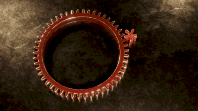
A ring gear, as the name suggests, is an annular-shaped gear with teeth either inside or outside the ring. Commonly used as the outer gear in planetary gear systems, a ring gear with internal teeth is also known as an internal gear.

A critical aspect of ring gears is their circular precision and tooth design. The shape and chamfering of the teeth significantly impact the gear’s smooth operation, meshing smoothness, and noise reduction.

Uses of Ring Gears

Ring gears are integral to systems requiring high reduction ratios, like drive plates in automatic transmissions and flywheel clutches in manual transmissions. Segment gears, created by cutting a portion of ring gears, are used in mechanical watches and clocks to transmit reciprocating motion.

Principle of Ring Gears

The functionality of ring gears is best understood within the context of planetary gears, where they are most commonly used. Planetary gear systems consist of sun gears, planetary gears, and ring gears, resembling planets orbiting the sun. These gears are held by a planetary gear carrier.

Planetary gears offer versatile combinations of input and output arrangements between the sun, planetary (carrier), and ring gears, allowing for different gear ratios and rotational directions. The configuration of these gears determines the gear system’s operation: fixing two gears results in a direct input-output connection while leaving one gear free with the other as input produces no output.

カテゴリー
category_usa

Miter Gear

What Is a Miter Gear?

Miter Gears

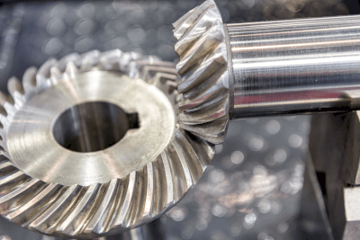
A miter gear, a specific bevel gear, is designed to transmit rotational motion to an orthogonal axis. This gear is typically shaped like the umbrella of a mushroom, and when two miter gears mesh at right angles to each other, they can effectively transfer motion.

While bevel gears come in various angles and tooth counts, miter gears are characterized by:

  • Meshing gears having an equal number of teeth, preventing compatibility with gears of different tooth counts.
  • Gears meshing at a 90-degree angle.

Consequently, miter gears are primarily used to alter the rotation direction by 90° while preserving the same rotational speed.

Uses of Miter Gears

Miter gears are crucial in transmitting rotation to a perpendicular shaft without altering the rotational speed. For instance, if shafts A and B intersect at right angles, miter gears attached to both shafts allow shaft B to rotate at the same speed as shaft A through seamless teeth meshing.

These gears are essential in applications like conveyor belts, machine tools, and automotive gears.

Principle of Miter Gears

As a subclass of bevel gears, miter gears are conical or mushroom-shaped, distinct in their 1:1 tooth ratio and a 90° crossing angle. This equal tooth count means miter gears are incompatible with gears having different numbers of teeth and must be mounted to intersect at 90 degrees.

Miter gears feature a keyhole-shaped hole for the rotating shaft, accommodating a keyed shaft. The shaft’s keyway aligns with the miter gear’s keyhole, and a metal fitting (key) secures the gear in place.

Typically made from S45C, a carbon steel for machine structural use, miter gears are hardened for enhanced tooth strength. Adequate bending strength prevents tooth breakage from the root, while sufficient tooth surface strength avoids chipping. It’s vital to adhere to specifications and ensure the mechanical device’s rotational energy stays within the gear’s load capacity.

カテゴリー
category_usa

Base Plate

What Is a Base Plate?

A base plate is a foundational component, typically a flat or thin plate, manufactured in various types for different applications. Its role and design vary significantly based on its field of use.

In machining, base plates are robust and thick, serving as stable platforms for securing workpieces. They often come equipped with high-precision holes to attach jigs and tools.

Uses of Base Plates

Base plates have diverse applications across multiple industries:

  • In machining, they function as tables for jigs and molds.
  • In construction, they are integral to building structures and mounting seismic isolation devices.
  • In electronics, particularly hard disk drives (HDDs), base plates are selected for their strength and thin profile.

Features of Base Plates

The material and characteristics of base plates vary based on their specific application:

  • For jigs and tools, common materials include S45C, S50C, SS400, SCM steels, and SUS303/304 or SUS400 series stainless steels.
  • For aluminum base plates, A2017 (duralumin), A5052 series, and A7075 are frequently used.
  • Base plates for jigs and tools typically feature numerous pre-drilled holes for mounting, providing versatility and eliminating the need for additional processing by users.
  • In equipment manufacturing, base plates are often custom-designed to meet specific customer requirements regarding material, shape, and dimensions.
  • In construction, materials are selected for their strength, durability, and air resistance. Seismic isolators, for example, use a pair of base plates – one on the ground side and the other on the building side – to encase the seismic isolation material.
カテゴリー
category_usa

Tool Presetter

What Is a Tool Presetter?

Tool Presetters

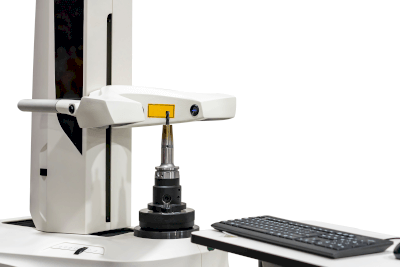
A tool presetter is a device used in machine tool operations to check for defects or dimensional variations in tools like drill bits. It’s essential for ensuring accuracy in the machining process, as a defective tool can lead to faulty operations and potentially render machined products unusable.

Tool presetters enable the inspection of a tool’s tip, shape, and size before its use, eliminating the need for risky and time-consuming in-machine inspections.

Uses of Tool Presetters

Tool presetters are commonly used in metalworking shops where machine tools are frequently operated. They help identify wear on drill bits and other tools, which can affect drilling speed, depth, and hole diameter. By using a tool presetter, operators can avoid such failures and maintain consistent quality in their work.

The measurements taken by tool presetters can be transmitted directly to the processing equipment for precise adjustments.

Principle of Tool Presetters

Tool presetters utilize three main methods to read the geometry of machining tools:

  • CMOS Camera Method: This method involves capturing images of the tool using a CMOS camera and displaying them on a monitor. It provides a three-dimensional perspective and can rotate the tool for comprehensive inspection. While offering high performance, this method tends to be more expensive due to the use of a CMOS camera.
  • Projection Type: This approach projects the tool’s shape using a light source. It allows for visual confirmation of the tool’s shape but cannot display three-dimensional details and outermost outlines. However, it is more cost-effective than the CMOS camera method.
  • Contact Type: This type measures the tool’s size by direct contact. It can determine the outer diameter and length but not complex shapes or detailed dimensions. This method is the most affordable but offers limited information compared to the other types.
カテゴリー
category_usa

Plastic Chain Conveyor

What Is a Plastic Chain Conveyor?

Plastic Chain Conveyors

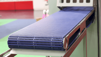
A plastic chain conveyor utilizes a plastic chain as its medium for conveying items. These conveyors are ideal for moving lightweight products, foodstuffs, and electronic equipment due to their light weight, ease of handling, and simplicity in installation and maintenance. They are a sustainable option, offering a quieter and environmentally friendlier alternative to metal conveyors.

Uses for Plastic Chain Conveyors

Plastic chain conveyors find applications across various industries:

1. Logistics

Used for transporting and sorting goods in warehouses and distribution centers, enhancing order fulfillment efficiency.

2. Food Industry

Preferred for transporting food products due to stringent hygiene standards, used in packaging and cooling lines.

3. Medical Devices

Essential in the assembly and inspection lines for medical devices, where cleanliness is paramount.

4. Electronics

Facilitates the transport of parts and products in the assembly and testing lines of electronic equipment.

Principle of Plastic Chain Conveyors

Plastic chain conveyors operate on a looped plastic chain driven by electric motors and pulleys. The chain’s design allows for both horizontal and vertical movements. However, plastic’s susceptibility to high temperatures limits its use to conditions below about 60°C.

How to Select a Plastic Chain Conveyor

Key factors in selecting a plastic chain conveyor include:

1. Conveyor Dimensions

Determine the conveyor length and width based on the size of the goods and the conveying route, considering space for potential future adjustments.

2. Speed

Choose conveyor speed based on material type and process requirements, with options for variable speeds to suit different needs.

3. Frame Material

Select frame material (e.g., stainless steel, aluminum) based on the operating environment and hygiene standards, particularly in the food industry.

カテゴリー
category_usa

Power Unit

What Is a Power Unit?
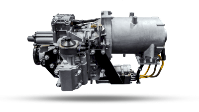
Power Units

A power unit is a device that generates power, such as an engine or motor for automobiles and other vehicles.

It is used as a power source for large equipment, such as various industrial devices. Since a power unit consists of an internal combustion engine, several motors, and a generator, it is called a power unit as an integrated power source.

Diesel engines are often used as internal combustion engines. The power generated by the diesel engine is transmitted to the hydraulic pumps and other devices to operate the machine.

Uses of Power Units

Power units are used to operate a variety of large machines. Examples include drainage pumps, oil pumps, agricultural machinery, construction equipment, and communications equipment. In these cases, hydraulic power units are often used.

Power units are also used to power F1 cars in Formula 1, a form of motorsports. The power unit is not only powered by a conventional engine but also by a hybrid turbocharged engine, which has been improved to reduce carbon dioxide emissions.

Principle of Power Units

Power units can be used to operate various industrial machines by using the power generated by diesel engines and other engines through multiple motors and other devices. While power units have long been used in industrial applications, recent years have seen the development of power units in Formula One.

Power units in F1 consist of an internal combustion engine, a turbocharger and battery, and hybrid devices, such as an energy recovery system. Computer control of these devices can improve fuel efficiency, engine performance, and exhaust emissions. Thus, Power units are becoming increasingly sophisticated in the automotive industry.

On the other hand, the term for devices including engines, transmissions, and clutches in automobiles is power plant. The term power plant is also used to refer to a power plant.

Other Information on Power Units

1. History of F1 Power Units

For more than 50 years after the start of F1, F1 cars have been running on fuel. F1 is not only a motorsport but also a development of next-generation technology.

In light of the depletion of oil and fossil fuels and environmental issues, F1 introduced a hybrid power unit in 2014. This power unit is packed with technology that produces high power with a small displacement.

2. Structure of the F1 Power Unit

The F1 power unit consists of the following components.

ICE
The ICE is an internal combustion engine, the equivalent of an engine. Previously, unimaginably high-power engines were used, but now they are defined as engines with a displacement of 1.6 liters and six cylinders.

TC
A TC, also called a turbocharger, uses the exhaust gas emitted from the engine to compress and feed air to the engine. By sending a large amount of compressed air, the power of the engine is increased dramatically.

The MGU-H, which is linked to the turbocharger, is a thermal energy regeneration system. It assists the rotation of the turbocharger. This, together with heat recovery, alleviates turbo lag, which is the biggest crying point of turbochargers.

MGU-K
The MGU-K is a kinetic energy regeneration system, which corresponds to a generator in a general hybrid vehicle.

The electric energy is sent to a battery for storage. The MGU-K also has a motor drive function, which uses the electrical energy in the battery to provide driving power as a motor.

MGU-H
The MGU-H is a thermal energy regeneration system that converts thermal energy from exhaust gases into electrical energy.

The converted electrical energy is stored in a battery, and the battery’s electrical energy is used to assist the turbocharger.

Other

  • ES
    A battery that stores the converted electrical energy.
  • CE
    An electronic device that controls the Power Unit.
カテゴリー
category_usa

Power Management System

What Is a Power Management System?

Power Management Systems

Power management systems are crucial for reducing system power consumption in various devices. As energy conservation becomes increasingly important, these systems have gained prominence for their ability to manage and save power efficiently.

In devices like automobiles, where advanced features lead to higher power usage, power management systems are essential. They optimize power usage by enabling low-power operation and shutting down when not in use.

Uses of Power Management Systems

These systems use computer controls to minimize power consumption in devices. For instance, the CPU in a computer may reduce or halt operations during periods of inactivity, as seen in PC sleep functions. Similarly, automotive control systems are incorporating power MOSFETs to reduce circuit power consumption.

Principle of Power Management Systems

Power management systems are vital in applications like automobile power devices, where energy conservation is critical. As automotive control circuits become more advanced, the load on the battery increases, leading to higher power consumption.

These systems often include semiconductor circuits known as Large Scale Integration (LSI) circuits within Electronic Control Units (ECUs). To manage power efficiently, it’s crucial to control the power consumption of these LSIs. Power management systems achieve this by using power management LSIs and power MOSFETs, known for their high power conversion efficiency, particularly in low-voltage applications.

With the growing number of LSIs in various industrial devices, including automobiles, the advancement of power management systems is becoming increasingly important.

カテゴリー
category_usa

Power Switch

What Is a Power Switch?

A power switch is a device that creates an electrical connection between power or ground and a load. These switches are categorized into two main types: IC-based switches, which utilize electronic circuits with components like MOSFETs on silicon substrates, and mechanical contact switches.

The term encompasses a wide range of switches, from simple mechanical load switches to smart power switches found in power management ICs, each tailored to specific applications.

Uses of Power Switches

Mechanical switches are widely used in applications requiring human interaction. They are essential in various devices and machines, such as industrial robots, home appliances, lighting equipment, automobiles, and personal computers. These switches come in various structures, including pushbutton, toggle, slide, seesaw, reed, rotary, and tactile types.

Toggle and rotary switches are often used for power on/off functions and circuit or power level switching. Tactile switches are commonly found in PC keyboards.

Principle of Power Switches

The basic principle of power switches involves physically switching electrical circuit connections. In mechanical switches, this is achieved by human operation, while in IC switches, it’s done through the ON/OFF operation of transistors like MOSFETs. The power circuit is controlled by the movement of electrode contacts in relation to fixed contacts.

Switches are technically defined by terms like ‘throw’ and ‘pole.’ ‘Throw’ refers to the number of control paths a switch can handle, while ‘pole’ indicates the number of circuits it can control simultaneously. For example, a ‘Double Poles Double Throws’ (DPDT) switch can control two circuits in two different ways.

With push-button switches, it’s important to distinguish between normally OPEN and CLOSE positions, indicating the switch’s state when pressed. Power switches also require careful consideration of maximum rating specifications, including current and voltage limits, to prevent overheating or damage due to arcing.

When selecting a power switch, considerations should include whether the bias is DC or AC and the specific load conditions, as these factors influence the switch’s current and voltage ratings.