カテゴリー
category_usa

Relay Socket

What Is a Relay Socket?

In electric circuits, a relay is an electrical component that uses an ON/OFF control signal to switch the output to or from an input signal.

A relay socket is a component mounted on a printed circuit board or built into a control panel, allowing for the relatively easy installation or removal of the relay itself.

Installation can be done by simply inserting the terminals from the relay body into the holes provided on the relay socket side or by securing them with a lever attached to the relay socket after insertion.

Uses of Relay Sockets

When relay sockets are placed on printed circuit boards or control panels, the footprint (the area occupied by the relay sockets on the board) is basically the same size as the relay itself, so there are few problems in terms of mounting area.

However, in the height direction, the relay sockets will certainly be taller than the relay directly mounted on the board.

Therefore, it is necessary to verify in advance using 3D structural drawings or by temporarily placing the relay and relay sockets in the actual position to ensure that there is no interference with other components in the structure of the product or other equipment to which it is to be mounted.

Principles of Relay Sockets

Relays and relay sockets are used in circuits that handle large currents, sometimes several amperes.

Therefore, the construction of relays and relay sockets is designed to provide sufficient insulation distance between the coil and the contacts, ensuring safety measures are taken to reinforce insulation.

The purpose of safety standards is to avoid problems that could result in electric shock to the user or, in the worst case, fire, depending on the operating environment (temperature, humidity, power supply conditions, etc.) and characteristics of the product when the equipment is used.

The IEC is the global technical standard that serves as the basis for safety standards. These standards have been developed by referring to the IEC standards and adding or modifying them as individual standards according to the circumstances of each country.

In Japan, the Electrical Appliance and Material Safety Law is based on the JIS standard, while in the US, the well-known UL standard is based on the ANSI standard. In Canada, the CSA standard, and in Europe, the EN standard are also well known.

カテゴリー
category_usa

Vertical Conveyor

What Is a Vertical Conveyor?

Vertical Conveyors

A vertical conveyor is a specialized conveying equipment designed to move objects or luggage vertically to different levels.

Distinct from elevators, vertical conveyors are specifically engineered for transporting goods in a vertical direction and are not meant for transporting people.

Compared to traditional cargo elevators, vertical conveyors typically offer higher transport capacity. They are not categorized as “elevators” under building regulations, thus simplifying installation by eliminating the need for building certification or permits from labor regulatory bodies.

Uses of Vertical Conveyors

Vertical conveyors are commonly used in factories, distribution centers, and warehouses to efficiently transport large loads. They are especially effective for moving carts and pallets simultaneously, handling substantial quantities of goods.

While elevators can also be used for vertical transportation of goods, vertical conveyors are often more cost-effective, approximately half the cost of installing an elevator when considering installation and procedural aspects.

Principles of Vertical Conveyors

While similar in function to an elevator, the structure of a vertical conveyor is more akin to a “shelf,” making it relatively simple. The main body frame houses a carriage (cage or platform) and weights, with the carriage being raised and lowered by a suspension chain or metal wire driven by a motor unit.

There are also conveyor-type vertical conveyors where the entrance is integrated with a conveyor belt. These types are particularly efficient and safe for continuous vertical movement of loads, such as in manufacturing plant lines.

While vertical conveyors offer cost advantages over elevators, it is important to note that the size and weight of the items to be conveyed are subject to strict guidelines set by the type of conveyor and the manufacturer, limiting what can be transported.

カテゴリー
category_usa

Heating Apparatuses

What Is a Heating Apparatus?

Heating devices are used to heat various objects such as scientific chemicals and samples using combustible gas or electricity.

Generally called “heaters,” there are a wide variety of products in circulation, ranging from industrial products capable of heating up to 1,000°C or higher to so-called “induction heaters” and “electric heaters” for general household use.

In recent years, in addition to improvements in production technology, electric heaters have become more common due to the ease of securing a heat source (power source) and safety.

Applications for heating apparatuses

Heating devices are extremely versatile and are used in a variety of industries.

For R&D of industrial products, heaters are used for “chemical heaters,” which are immersed in a chemical solution and heated from the inside, and heaters for “constant temperature storage,” which are used to store chemicals or powdered objects that easily scatter in a high-temperature state. In addition, “bar heaters” or “electric stoves” are used to heat materials in oil when hard-fitting ring gears, bearing inner races, and the like.

In addition, “high-frequency heating equipment,” which can heat to extremely high temperatures, is used as a metal melting furnace because it can self-heat metal to ultra-high temperatures exceeding 1,000°C without contact.

Features of heating apparatuses

Taking the aforementioned product as an example, a “chemical heater” is a “rod heater” coated with a fluoroplastic or other material that excels in corrosion and weather resistance, so it is resistant to erosion even when immersed in a chemical solution.

Also, “rod heaters” used for heating liquids such as water and oil can directly heat the liquid from the inside of the container instead of from the outside, thus reducing the time required for temperature rise.

Unlike “high-frequency heaters” and “induction heaters” that use Joule heat generated in electric heating wires or heating elements, “high-frequency heaters” and “induction heaters” use “self-heating phenomenon (Joule heat)” generated by electromagnetic induction, which can heat an entire object evenly. The temperature can be easily varied from low to ultra-high temperatures by controlling the output power. In the case of metal melting furnaces, the electromagnetic force stirs the inside of the furnace, and this feature makes the furnace very easy to use in terms of operator load and work environment.

Other products using silicone rubber can be freely deformed. Those using transparent conductive films, such as those used to prevent fogging of the glass, have the feature of not interfering with vision.

カテゴリー
category_usa

Three-Phase Motors

What Is a Three-Phase Motor?

三相モーター

Three-Phase Motor is an electric motor driven by a three-phase AC power source.

They are widely used as power sources for industrial equipment and machinery. Also called three-phase induction motors (induction motors), they are generally powered by a three-phase AC power supply of 200 VAC.

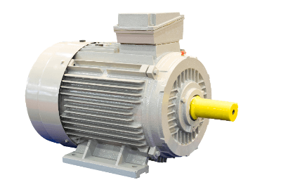
Three-Phase Motors consist of a stator, rotor, output shaft, flange bracket, and ball bearings.

Usage of Three-Phase Motor

AC power supplies are classified as single-phase and three-phase. Single-phase is an AC power source mainly used in general households. On the other hand, three-phase motors are mainly used in the industrial field.

Specific applications of Three-Phase Motors are as follows

Three-Phase Motors have a wide range of applications and are used in many industrial machines other than those listed above.

Among Three-Phase Motors, there are also stepping motors and servo motors, which are used to precisely control rotation. These are used in the use of automated machinery such as industrial articulated robots.

Principle of Three-Phase Motor

In Three-Phase Motors, three-phase AC power with a phase shift of 120 degrees is applied to the coils of a stator, and the coil to an electromagnetic steel plate becomes an electromagnet, forming a magnetic field inside the motor. The polarity of the electromagnet is determined by the direction of the current flowing through the coil and the right-hand thread law.

Since the AC power source is out of phase with time, the direction of the magnetic field rotates with time.

Figure 1 shows the principle of generating a rotating magnetic field. As the phases of the U, V, and W phases of the three-phase AC power supply change, the direction of the stator’s magnetic field changes (in Figure 1, the rotating magnetic field rotates counterclockwise).

3136_Three-Phase-Motors_三相モーター-1.png

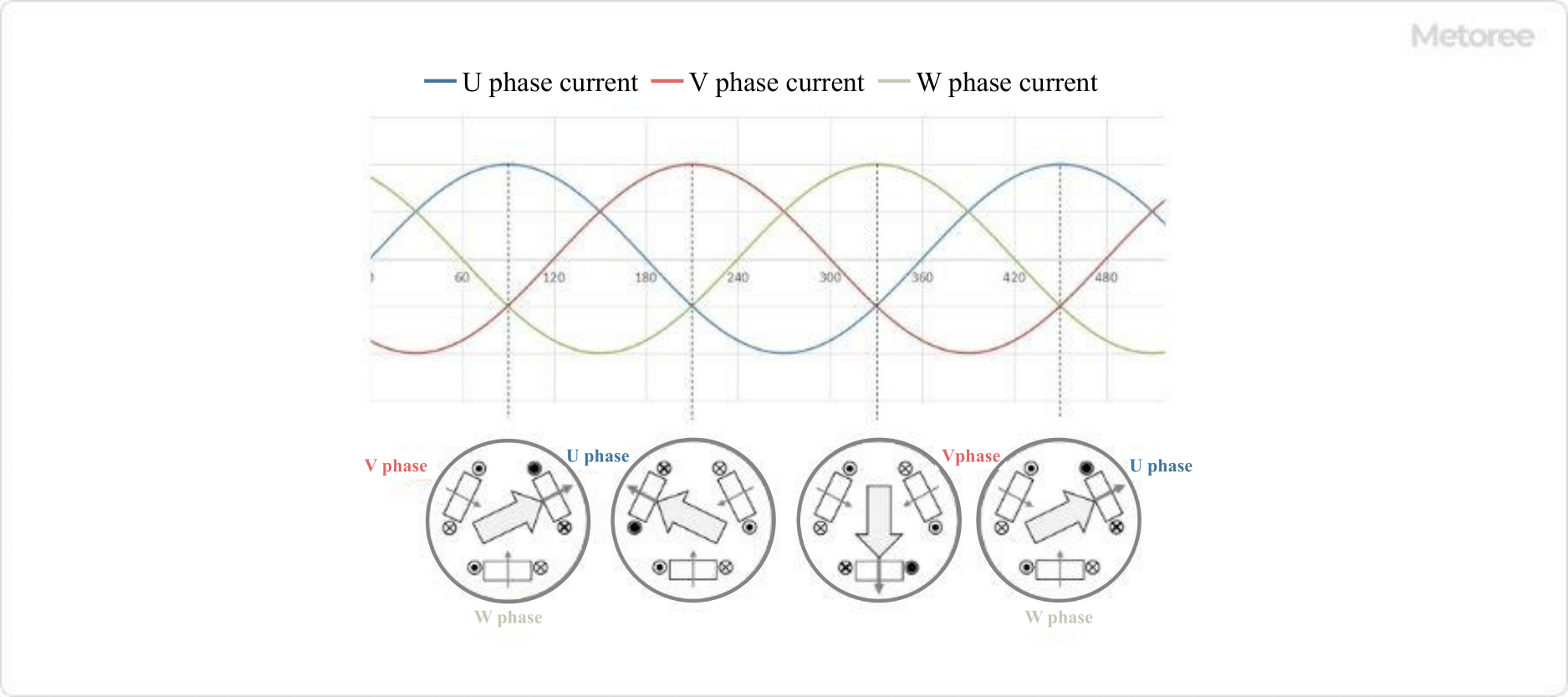
Figure 1. The principle of rotating magnetic field generation

The rotation of the magnetic field generates eddy currents to the rotor, and the eddy currents and the magnetic field generate a force on the rotor. As a result, power is generated on the motor’s rotating shaft. The direction of the rotational force of the motor is determined by Fleming’s left-hand rule.

The speed of the rotating magnetic field as the rotor rotates is called the synchronous rotation speed. The synchronous rotation speed can be calculated from the frequency of the power supply and the number of stator poles.

The actual rotational speed of the rotor is slightly slower than the synchronous rotational speed. This is because the magnetic flux crossing the rotor conductors generates an induced current that causes the rotor to rotate.

The difference between the synchronous rotation speed and the actual rotation speed is called “slip.” The greater the load torque, the greater the slip. The output (W) of a motor can be calculated from its rated rotational speed and rated torque.

Other Information on Three-Phase Motors

1. Wiring for Three-Phase Motors

Three-Phase Motors are wired differently depending on the starting method. Four types of starting methods are introduced here.

Direct-in Starting
Three-Phase Motors are started by applying three-phase AC power directly to their terminals via an electromagnetic contactor. Wiring is easy, but the current flowing through the motor during starting (starting current) is large, several times the rated current.

This method is often used with small capacity motors that require a low starting current.

Star-Delta Starting
This is a starting method that starts with star wiring and then switches to delta wiring.

There are two types of motor wiring: star-wired and delta-wired (Figure 2). Star-wiring requires only 1/3 of the starting current of delta-wiring, so it is the starting method used for Three-Phase Motors with a high rated current.

3136_Three-Phase-Motors_三相モーター-2.png

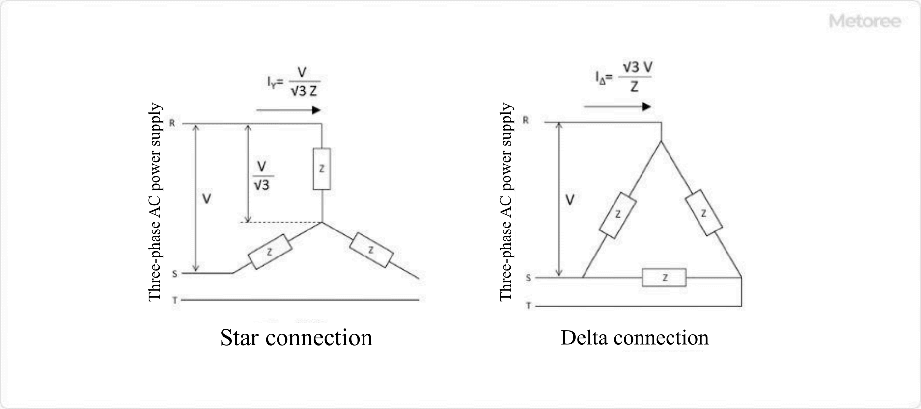
Figure 2. Star and delta connections

The terminal box of a star-delta starting motor has six terminals (U, V, W, X, Y, and Z). Outside the stator windings is a circuit that combines an electromagnetic contactor and a timer to automatically switch between star and delta wiring.

Reactor Starting
A reactor is connected between the Three-Phase Motor and the power supply at startup, and the circuit of the reactor is disconnected with an electromagnetic contactor and timer a short time after startup.

Inverter Starting
An inverter is an electrical device that controls the speed of a Three-Phase Motor (Figure 3). It can freely change the output and frequency of the three-phase AC power supply.

By installing an inverter, the motor can be started from a low frequency of a few Hz and the starting current can be reduced.

3136_Three-Phase-Motors_三相モーター-3.png

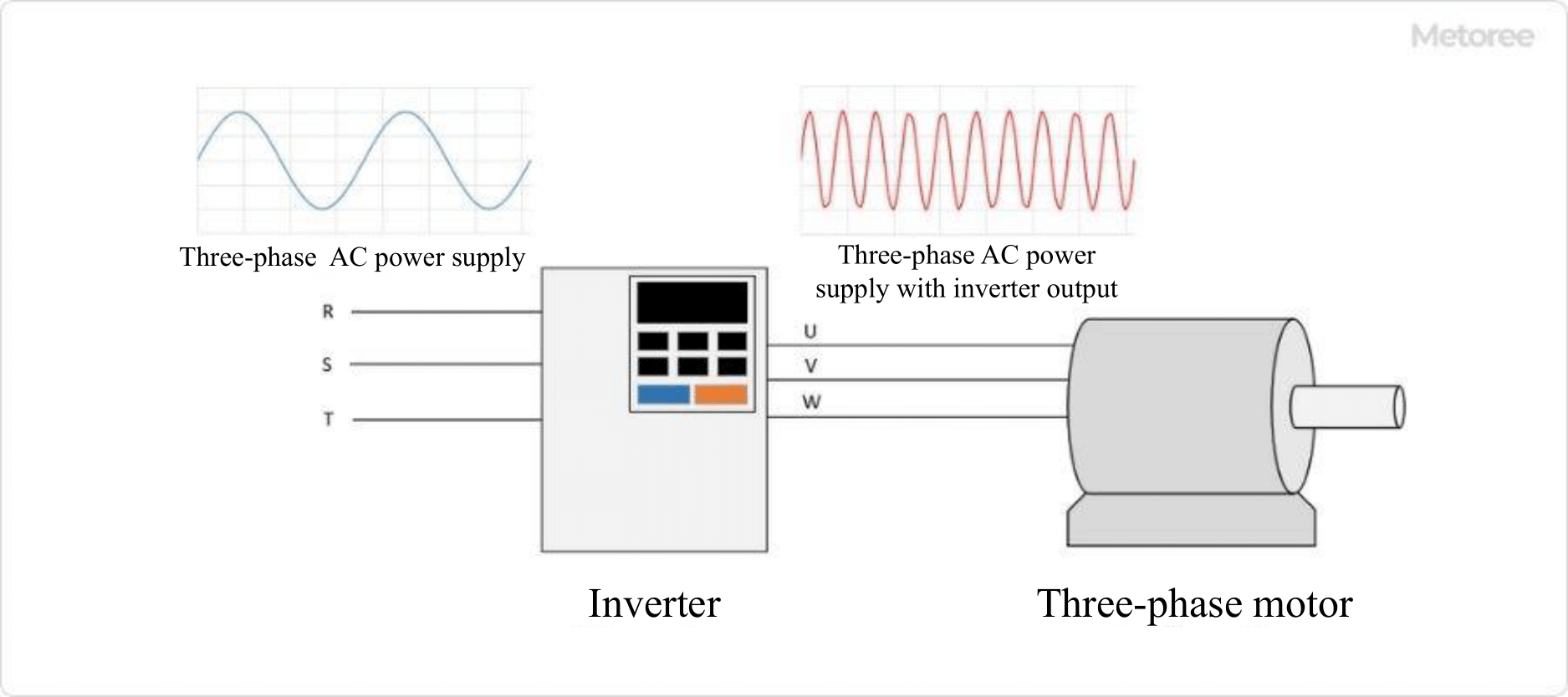
Figure 3. Three-phase motor and inverter

2. Rotational Speed of Three-Phase Motor

The formula for the number of revolutions is 120 x the frequency of the AC power source/number of poles.

For example, for a 4-pole motor with a 50 Hz power supply, the number of revolutions is 120 x 50 ÷ 4 = 1500 rpm.

However, Three-Phase Motors rotate with a slight lag behind the power supply frequency. This delay is expressed as the slip ratio. If the slip ratio is 5%, the speed will be 1500 x (1-0.05) = 1425 rpm.

To control the speed of a Three-Phase Motor, either the frequency or the number of poles must be controlled, but the number of poles cannot be changed because of the structure of the motor. Therefore, the frequency must be changed to control the speed. Currently, inverters are the most common way to control the speed of Three-Phase Motors.

カテゴリー
category_usa

Hygrothermograph

What Is a Hygrothermograph?

Hygrothermographs

Hygrothermographs are instruments that simultaneously measure and record temperature and humidity.

They are used both indoors and outdoors to monitor environmental conditions accurately. By tracking temperature and humidity, hygrothermographs aid in effectively managing air conditioning and humidification systems, ensuring comfortable living and working environments. These measurements are also crucial in industrial settings, where environmental conditions directly impact product quality and efficiency. In extreme conditions, such as high heat and humidity, they play a vital role in maintaining safety and preventing health risks like heatstroke.

For accurate readings, it’s essential to regularly calibrate hygrothermographs. Selecting a high-precision instrument is especially important in critical applications, and the accuracy should be confirmed based on specifications or manufacturer guidelines.

Applications of Hygrothermographs

Hygrothermographs are versatile and find applications in various fields:

1. Living Space Management

These devices help maintain comfortable and healthy indoor climates by monitoring room temperature and humidity. Proper environmental control can also lead to energy savings.

2. Industrial Process Control

In industries such as semiconductor manufacturing and chemical storage, strict control of temperature and humidity is essential. Hygrothermographs ensure consistent quality by monitoring these parameters during production.

3. Agriculture

Monitoring temperature and humidity is crucial for optimal crop growth. Hygrothermographs help in enhancing crop yield and quality and are instrumental in predicting and managing pest outbreaks.

Principle of Hygrothermograph

Hygrothermographs measure temperature and humidity using various sensors:

– Temperature is typically measured using electrical resistance sensors, thermistors, or thermocouples. These sensors respond to temperature changes by altering electrical resistance or generating a voltage difference.

– Humidity is measured with moisture-sensitive resistance sensors or capacitance sensors, which change resistance or capacitance in response to humidity levels.

Digital hygrothermographs convert these sensor signals into digital data, displaying the measurements on an integrated display.

How to Select a Hygrothermograph

Consider the following when choosing a hygrothermograph:

1. Size

Select a size appropriate for the intended location. Smaller devices are portable for personal use, while larger units are better for wall mounting in larger spaces.

2. Measurement Range

Ensure the device covers the necessary temperature and humidity ranges for your environment. Wider ranges are preferable for diverse or extreme conditions.

3. Power Supply

Choose between battery-powered or AC-powered models based on portability needs and usage duration. Battery-powered models offer flexibility, while AC-powered devices are suitable for continuous, long-term monitoring.

カテゴリー
category_usa

Button Die

What Is a Button Die?

A button die is a component used in the lower die plate of a mold for nesting. It is designed to be easily removed, polished, and replaced, allowing for prolonged use and maintenance. Typically used in die plates not subjected to hardening, button dies facilitate easy fabrication and maintenance of dies.

Uses of Button Dies

Button dies serve as crucial parts in die plates for creating and finishing holes, especially in non-hardened materials. They are integral to the drilling process, acting as the lower blade while the punch serves as the upper blade. Their design allows for the removal and regrinding of worn blades, enhancing longevity and performance in hole processing.

Principle of Button Dies

The button die is the part of the blade that needs to be hardened to prevent wear. However, the lower die does not need to be hardened.

It can be processed by punching. During processing, it is necessary to penetrate the hole so that the cut shavings can fall as a countermeasure against hole jamming to avoid the punch breaking and damaging the product. In addition, the remaining processed shavings may fly out of the surface of the button die, and if processed in this state, dents will remain on the product, so care must be taken.

Structure of Button Dies

The hole in a button die consists of a relief section and a land section, and there are three types of cross sections. Some button dies have a tapered land section to allow the material to pass through. The disadvantage, however, is that the hole gradually becomes larger during regrinding.

There are also button dies that have a straight section where regrinding is required, so that the dimensions of the hole do not change during regrinding. On the other hand, button dies that do not have a large relief at the bottom of the land area, but instead have a straight land area with a tapered relief at the bottom, are called angular button dies. Angular button dies are easy to use for pulling out small-diameter holes, taking into consideration the possibility of clogging.

Types of Button Dies

Button dies come in various forms, including straight and standard types with collars, and are made from materials like powdered HSS, cemented carbide, SKD11, and SKH51. They are designed to fit into plates either with a press-fit or using spacers for adjustment, accommodating regrinding without altering hole dimensions significantly.

Selecting a Button Die

Selection depends on the ability to regenerate cutting edges through regrinding. Considerations include the method of regrinding (whole plate vs. nested parts), ensuring evenness post-polishing to avoid quality issues, and adjusting the “L” dimension for optimal performance, especially in preventing clogging for small diameter holes. Proper adjustment and selection criteria are essential for maintaining quality and efficiency in drilling operations.

カテゴリー
category_usa

Torque-Measuring Instrument

What Is a Torque-Measuring Instrument?

A torque-measuring instrument is a device designed to measure the rotational force, or torque, of an object or machine.

Torque is the force that causes rotation. These instruments are crucial in various applications, including machine and engine performance evaluation, quality control, and accurate torque adjustment. Proper torque setting enhances machine efficiency and reduces energy wastage. In manufacturing, accurate torque measurement ensures product quality by preventing defective assembly.

Regular calibration of torque measuring instruments, as recommended by manufacturers, is essential for maintaining accuracy.

Applications of Torque-Measuring Instruments

Torque-measuring instruments are vital in numerous industries. Some of their applications include:

1. Automotive Industry

In the automotive sector, precise torque application is critical for engine bolt assembly and tire installation, directly impacting operational reliability and vehicle safety.

2. Aerospace Industry

These instruments are integral in assembling aerospace components like engines, wings, and frames, where precision and reliability are paramount.

3. Machinery Industry

Correct torque application is crucial for assembling bearings and other machine components. It also affects power transmission in clutches and transmissions, influencing machine operation and load control.

Principles of Torque-Measuring Instruments

Two common types of torque measuring instruments are the Strain Gauge Type and Ultrasonic Type.

1. Strain Gauge Type

This method involves attaching a strain gauge to an object’s surface to measure stress changes caused by torque. The resulting resistance change is converted into a torque value. It’s widely used in the automotive and aerospace industries.

2. Ultrasonic Type

The ultrasonic method detects slight object deformations due to torque by measuring ultrasonic wave propagation times. This non-contact measurement approach offers high accuracy and reliability.

How to Select a Torque-Measuring Instrument

Key factors to consider when selecting a torque-measuring instrument include:

1. Measurement Accuracy

Accuracy is crucial in torque measurement. For instance, an accuracy of ±1% means the measured value could vary by up to ±1% from the actual torque. Choose an instrument that meets your accuracy needs.

2. Measuring Range

The measuring range should cover the torque requirements of your application, usually expressed in Newton meters (N-m).

3. Measurement Direction

Ensure the instrument can measure torque in the necessary direction(s), whether clockwise, counterclockwise, or both.

カテゴリー
category_usa

Hammermills

What Is a Hammermill?

HammermillsA Hammermill is a device that can instantaneously grind various raw materials by feeding them through a hopper and rotating a hammer installed on the rotor at high speed, thereby impacting the fed materials.

The hammer part can be a movable or fixed type, and the rotation speed can be changed to change the particle size of the material. The screen part is attached to the outlet after processing and used as a filter, and by changing the mesh of the screen, the particle size can be uniformly adjusted.

Therefore, by changing the combination of hammers and screens, the mill can be used for a wide variety of applications.

Uses of Hammermills

Hammermills are used for fine grinding, i.e., to grind particles of a few centimeters to a size of 10 to 1 micron. Hammermills are used for a wide variety of applications, ranging from the processing of building materials to food and pharmaceuticals.

There are different types of hammermills, depending on their purpose and use. Hammermills with fixed hammers are used for grinding and processing raw materials, and are suitable for soft materials such as grains, or when the required load is small and the rotation of the hammer is low.

Hammermills with movable hammers are suitable for hard materials such as ores and wood, or when a large impact is required for crushing.

Principle of Hammermill

Hammermills grind by rotating the hammer at high speed and swinging the hammer to impact the object to be processed. Therefore, the impact can be adjusted according to the material and application of the object by the rotation speed of the hammer and the swinging motion.

A screen is installed at the outlet of the crushed workpiece to adjust the particle size after processing to ensure consistent quality. Although the machine is noisier and vibrates more, it is characterized by its high crushing capacity and ability to process relatively hard materials.

In addition, its simple structure makes it easy to disassemble, reassemble, replace parts, and perform other maintenance. In addition, the use of super steel makes it possible to take countermeasures against wear, so it has a long service life and can be used for a long period of time.

Cautions for Hammermills

Hammermills have a simple structure and can be used to grind various types of materials, but there are some points to note. Hammermills are suitable for hard, brittle, and easily broken materials because the impact force of the hammer crushes the sample. On the other hand, elastic or fibrous materials such as plastics cannot be crushed very finely.

In addition, for not only hammermills, but also other dry mills, it is difficult to grind materials with water or oil content, such as food, because they stick to the equipment or clog the screen. In addition, hammermills can heat up when operated for long periods of time, so care must be taken when grinding heat-sensitive samples.

Thus, it is important to select the appropriate milling machine depending on the sample to be milled, since the appropriate milling mechanism varies depending on the material characteristics.

カテゴリー
category_usa

Barbed Fitting

What Is a Barbed Fitting?

A barbed fitting is a type of fitting characterized by its jagged, bamboo shoot-shaped design.

These fittings are primarily used at connection points between hoses and tubes and are sometimes referred to as hose nipples or bamboo shoot fittings. Some variations include hexagonal hose nipples that can be securely tightened using a wrench and are often combined with fittings and elbows.

Barbed fittings are known for their affordability and compact size, making them a popular choice in applications where pressure resistance is required.

Applications of Barbed Fittings

Due to their cost-effectiveness, barbed fittings are frequently used in conjunction with hose bands at the junctions of rubber hoses and urethane tubing.

The sizing standard for barbed fittings is typically expressed as the thread diameter of the pipe multiplied by the outside diameter of the bamboo shoot. It is recommended that the outside diameter of the bamboo shoot be slightly larger than the inside diameter of the hose to ensure a proper seal.

Using a bamboo shoot size that matches the hose’s size is essential for achieving the intended hose grip on the fitting and preventing leakage.

Principle of Barbed Fittings

The effectiveness of barbed fittings relies on the hose or tube securely gripping the bamboo shoot portion, ensuring a tight seal.

Choosing the correct size is crucial as a size too small can lead to leakage, while a size too large may damage the tubing or hose and result in improper fitting during installation, rendering it unusable.

For applications with fixed hose sizes and frequent installations, specialized fitting installation tools are available. These tools help reduce variations in installation and enhance installation quality.

Barbed fittings come in a wide range of materials, including nickel-plated brass, stainless steel, and plastic resin. Selecting the most suitable material depends on factors such as shape, outer diameter, cost, and operating environment (temperature, pressure, etc.). This applies to hose extension joints as well as branching T-type and elbow applications.

カテゴリー
category_usa

Constant Force Spring

What Is a Constant Force Spring?

A constant force spring is a type of spring that generates a consistent load regardless of the distance it is stretched.

These springs are utilized when there is a need to support a constant load. Unlike traditional wire springs commonly found in daily life, which are made of coiled metal wire, constant force springs have a distinctive design. They consist of a thin plate wound around a drum, and when pulled externally, the drum rotates, extending the spring.

Constant force springs have a relatively simple structure, making them easy to design and install. This simplicity can lead to cost savings. When properly designed and manufactured, constant force springs can maintain stable performance over extended periods.

However, it’s essential to note that constant force springs are designed for specific load ranges and may be vulnerable to loads beyond that range. When unexpected loads may be applied, it’s crucial to consider an appropriate safety margin.

Applications of Constant Force Springs

Constant force springs find applications across various industries. Here are some examples:

1. Buildings and Structures

Constant force springs are used for various purposes in buildings and structures. In bridge supports, they help distribute loads evenly, supporting the weight of bridge loads and vehicular traffic. This equalization of load distribution enhances stability.

They are also employed in building foundations to stably support the structure’s weight, mitigate ground subsidence, and reduce the risk of building distortion, particularly in earthquake-prone areas.

2. Door Hinges

Constant force springs are used in mechanisms like door hinges to support a specific weight. This ensures smooth door movement and stable operation during opening and closing, particularly for larger doors.

3. Weight Adjustment of Industrial Products

In industrial machinery and production lines, maintaining consistent product weight is sometimes necessary. Constant force springs are often employed to achieve this by keeping the product’s weight constant. This ensures uniform product quality and stability in the production line.

Additionally, it helps prevent machinery malfunctions and issues arising from fluctuating product weights.

Principle of Constant Force Spring

Constant force springs are specialized springs designed to support a constant load, based on fundamental principles of mechanics. The key principles involved are Hooke’s Law and the law of action-reaction.

Hooke’s Law is a fundamental concept in mechanics that describes the linear relationship between stress and displacement for elastic materials. According to this law, stress and displacement are proportional within the elastic deformation range. Constant force springs are designed based on Hooke’s Law and achieve their ability to support a constant load by generating a reaction force through deformation when a load is applied.

In addition, constant force springs are often adjusted to provide a consistent displacement within the specified load range. Achieving equilibrium between the external force applied to the constant force spring and the reaction force generated by the spring is crucial. This equilibrium allows for the support of a constant load.

Constant force springs are designed to maintain a constant load by utilizing Hooke’s Law and ensuring equilibrium between external forces and reaction forces. By selecting appropriate materials and dimensions and manufacturing constant force springs to suit their intended purpose, structures and devices with high stability and reliability can be achieved.

How to Select a Constant Force Spring

When choosing a constant force spring, several essential factors should be considered. Here are some examples:

1. Spring Material

The material of the constant force spring affects its elastic properties and durability. Commonly used materials include steel or stainless steel. The choice of material should align with the specific application’s requirements, taking into account factors like elastic deformation range and strength.

2. Drum Material

The material of the drum on which the constant force spring is wound is crucial. The drum is responsible for winding and holding the spring, so it must be robust and durable. Materials like steel or hard plastic are often used for the drum. The choice of drum material can impact the spring’s applicability and durability, so it should match the operational environment and purpose.

3. Rated Load

The load rating of a constant force spring indicates the range of loads it is designed to support. The selection of a constant force spring should consider the expected load applied to the equipment or structure in which it will be used. Exceeding the load rating can result in unexpected deformations and potential safety and performance issues.

4. Dimensions

Dimensional parameters, including length, outside diameter, and the number of turns, are critical in constant force spring design. These dimensions influence stiffness, deformation, and stress distribution. Careful consideration of these dimensions is essential to meet specific application requirements.