カテゴリー
category_usa

Infrared Lamps

What Are Infrared Sensors?

Infrared SensorsInfrared sensors are sensors that detect light rays in the infrared region.

Light differs in color and characteristics depending on its wavelength. The wavelength of visible light is considered being around 400 nm to 800 nm, and light other than that is not visible to the eye. To the human eye, light rays in the 400 nm range appear purple, while light rays in the 800 nm range appear red. When referring to invisible light, light with a wavelength of 400 nm or less is called ultraviolet light, and light with a wavelength of 800 nm or more is called infrared light.

Infrared sensors are sensors that detect the above mentioned infrared rays. However, in addition to detecting infrared rays, there are also methods that emit infrared rays and detect reflected waves.

Uses of Infrared Sensors

Infrared sensors are used in a variety of ways in consumer products. A typical use is in TV remote controls. The TV’s infrared sensor receives the remote control’s operation signal. This takes advantage of the invisible nature of infrared light.

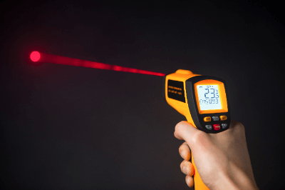
Infrared sensors are also used in thermometers. The temperature is detected using the characteristic that the hotter the substance is, the more infrared light it emits. Since temperatures can be detected quickly and without contact, they are useful during infectious disease outbreaks.

Infrared sensors are used in a wide range of industrial applications, including space development and military applications.

Types of Infrared Sensors

Infrared sensors have been actively researched and are available in a variety of materials. The principles are mainly divided into thermal and quantum types.

Infrared sensor wavelengths are classified into near infrared, mid infrared, and far infrared, and each sensor has its own area of expertise.

1. Thermal Infrared Sensors

A typical example of a thermal infrared sensor is a pyroelectric sensor. Pyroelectric infrared sensors are made of ferroelectric pyroelectric ceramics and utilize the pyroelectric effect. When the infrared sensor is heated, the amount of electric charge on the ceramic changes due to the pyroelectric effect. The sensor detects the electric current that flows according to the changed amount of charge. Even the slightest infrared radiation emitted from the human body can be detected.

Thermopile sensors are also a type of thermal type. A thermopile is a thermo-electromotive sensor that consists of multiple thermocouples and converts the thermal energy of infrared sensor into an electromotive force. 

2. Quantum Infrared Sensor

Quantum infrared sensors are sensors that detect band gap energy as an electric current. The mechanism is the same as that of solar panels, which are made of elements that generate electricity from infrared rays. While the detection sensitivity is 100 to 1,000 times higher than that of thermal sensors, the heat generated by the sensor itself is also detected, so it must be cooled sufficiently.

Other Information on Infrared Sensors

1. Disadvantages of Infrared Sensors

Infrared sensors can malfunction or fail to operate. Cases of malfunction include when the sensor is blocked by an object that does not transmit far infrared sensors, such as glass or acrylic, or when the object to be detected is hardly moving.

Let us use an automatic door as an example. Automatic doors detect objects by the rate of change of infrared reflection. Due to its principle, if a persons wears clothes of the same color as the carpet or approaches an automatic door slowly, it might malfunction.

Heat sources other than the human body can also cause malfunctions. For example, infrared devices may malfunction in response to sunlight or incandescent light. Malfunctions can also occur when there is a sudden change in temperature in the vicinity of air conditioning or heating equipment. 

2. Infrared Sensors and Automobiles

Driving at night increases the probability of accidents due to poor visibility. Infrared sensors are gaining attention as the new eyes that can solve nighttime driving problems and increase safety.

Night Vision Systems
Infrared sensors are used to identify pedestrians and other objects and visualize them on a display. Passive-type sensors directly detect far-infrared radiation, eliminating the need for light illumination.

The active type uses near-infrared lights to illuminate the road ahead, and the reflected light is captured by an infrared camera.

Vehicle Perimeter Monitor
Infrared cameras are installed on all four sides of the vehicle to detect pedestrians in blind spots. If pedestrians are present, an alarm is triggered when the vehicle starts, and a system has been developed to deter the vehicle from starting.

Air Conditioning Systems
An air conditioning control system has been developed that measures the surface temperature using far-infrared radiation emitted from the occupants and switches the air outlets.

カテゴリー
category_usa

Hydraulic Presses

What Is a Hydraulic Press?

油圧プレス

A hydraulic press is a device that uses hydraulic pressure as its power source to apply pressure to thin sheet metal and process it into the shape of a die.

The hydraulic motor sends oil to the hydraulic cylinder, and the piston in the hydraulic cylinder slides the die up and down to press it. Hydraulic presses are characterized by the speed of the slide, the pressure at the time of operation, and the long stroke. On the other hand, there is a risk of falling accidents due to oil leakage, etc., which must be considered when using hydraulic presses.

Applications of Hydraulic Presses

Presses are available in mechanical and servo motor types, depending on the operating system.

Although hydraulic presses have relatively slow production speeds, they can handle a wide range of materials and allow precise control of press speed, acceleration, force, and stroke length. In addition, large compression capacity can be obtained on a relatively small scale. These features make them suitable for small-scale production, drawing, and bending.

Hydraulic presses are mainly used in the processing of sheet metal materials for automobiles, home appliances, and electrical equipment. The types of presses available include cutting presses, deep drawing presses, injection presses, forming presses, punching presses, and forging presses. When selecting a press, it is necessary to consider the amount of press pressure, length of stroke, size of the press to be handled, and safety aspects. Examples of hydraulic presses in use are shown below.

  • Pressing of a car body
  • Pressing of gear outlines
  • Pressing metal parts of lunchboxes and bathtubs

Principle of Hydraulic Presses

Hydraulic presses use Pascal’s principle to produce a large force with a small force. Pascal’s principle states that fluid in a closed container, regardless of the shape of the container, transmits the pressure per unit area received at one point directly to all other parts of the fluid. For example, in the figure below, F1/A1 = F2/A2 because the pressures on both sides are balanced, and F2 = F1 × A2/A1. In other words, the larger the area ratio, the more force can be generated. 

Also, the principle of leverage allows the force (f) at the force point of the lever to be transmitted as a larger force (F1) at the point of action. By utilizing these two principles, a very large force can be generated even by human power.

It is important to note here that the larger the area ratio of the two sides, the greater the force that can be generated, but at the same time, the length that can be moved (stroke) becomes shorter. The stroke is determined by the amount of oil that is pushed out, and the larger the area ratio, the smaller the amount of oil that can be pushed out, resulting in a shorter stroke.

Hydraulic Press Structure and Principle of Operations

1. Principle of Operations

In the explanation of the principle, the manual method using a lever is briefly explained. However, hydraulic presses used industrially need to apply very large force precisely, so they use a hydraulic pump to push out oil. The following is an explanation of the operating principle of a hydraulic press. 

A hydraulic press consists of a hydraulic pump, hydraulic cylinder, pressure control valve, flow control valve, directional valve, hydraulic tank, and a press section. The hydraulic pump, pressure control valve, and hydraulic cylinder are connected to the hydraulic tank. The pipe extending from the hydraulic pump is connected to the pressure control valve, flow control valve, and hydraulic cylinder.

2. Structure of Hydraulic Presses 

When the hydraulic press is in operation, oil is transported from the hydraulic tank to the hydraulic cylinder by the hydraulic pump through pipes. At that time, the pressure and flow of the oil are adjusted by the pressure control valve and flow control valve to achieve the target pressure and stroke speed. The hydraulic cylinder is then pushed by the oil to operate the cylinder press. When the press is completed for the set time, the oil used is sent from the hydraulic cylinder to the hydraulic tank. It is possible to control compression by the cylinder, stop, and return the cylinder by means of a directional valve.

酸水素混合ガス発生装置

監修:T・D・S 株式会社

酸水素混合ガスとは

一般的に日本国内では、「ブラウンガス」「HHOガス」「パワークリーンガス」等の名称で呼ばれており、水を特殊な方法で電気分解することで発生し、その成分比は水素成分約66%、酸素成分約30%となっております。単なるH2とO2との混合とは異なり、水素原子(H)と酸素原子(O)とが原子状態を維持したまま結合し、結果としてガスの状態で発生し、着火すると青白い炎を出しながらで連続燃焼する(燃焼温度は約3,500℃以上)ことが大きな特徴で、この現象により、人が吸引した場合の効果や、発電等のエネルギー源に応用した際、他のガスでは見られない絶大な効果が発揮されます。

酸水素混合ガス装置の特徴

装置の基本的なシステムとしては、酸水素混合ガスを発生させる「セル」と、このセルに特殊な「水」を供給するタンク及び直流電源装置からなる構造が最も簡単なものであり、これら3要素の部品のサイズや供給電源の容量を変更することで、ガスの発生量が決まります。ガスの発生量の単位は基本的には○○cc/分です。具体的には各メーカーごとにそれぞれ特徴の異なる方法で、より安全で大容量のガス発生装置の開発に努めておりますので、以下に示すメーカーの資料を参照して下さい。

酸水素混合ガス発生装置の使用用途

この装置にて生成される酸水素混合ガスの用途としては、その発生量からガス吸引用及び美容用とクリーンエネルギー源としての利用の2種類に大別できます。

1.酸水素混合ガスの吸引による人の健康増進効果(ガス発生量:1,000cc/分~3,000cc/分)

このガスには、水素ガスだけでなく水素ガスのサイズと同程度の酸素ガスが含まれている為、顔等皮膚へ照射した場合、素早くこれらの成分が内部に吸収される為皮膚の殺菌や水分補給効果が発揮されます。又、吸引した場合、ほとんど瞬間的に血液中に高濃度の酸素が取り込まれることで、コロナウィルス等のウィルス感染症に罹ってもその重症化が防止されます。

その具体的な事例としては、下記があります。

1.コレステロール値の改善・血糖値の低下
2.バセドウ病や膠原病等血液や自律神経系に起因する病気の改善
3.認知症の予防と改善
4.乳酸の分解作用もあることから、スポーツ選手の疲労を急速に回復でき、新記録続出に貢献している。
5.近年、装置メーカーや医療専門家等による関係者の研究と治験例から、ミトコンドリアの核にまで、このガスに含まれている酸素が素早く供給されることで、ガン細胞の増殖防止と消滅効果が確認されております。

2.クリーンエネルギー源としての利用(ガス発生量:5,000cc/分以上)

水の電気分解によって発生した酸水素混合ガスは、燃焼させてもエンジンの燃料として使用しても、CO2をはじめ人体や地球環境を破壊するような有害物質を含んだ排出ガスの排出は、ゼロであるため以下のような分野への応用があり既に実用化されております。

1.家庭用電力供給システム—出力が5KWh程度のガス発電機用燃料

2.この発電機を搭載した充電不要の無限走行電気自動車の開発

3.原発に替わる爆発しない安全な排気ガスゼロの大規模発電システムの構築

特に3のシステム構築により、化石燃料の争奪に伴う国際紛争もなくなることが期待できます。正に究極的なSDGsが実現されることとなります。

本記事は酸水素混合ガス発生装置を製造・販売するT・D・S 株式会社様に監修を頂きました。

T・D・S 株式会社の会社概要はこちら

作業手順書

監修:株式会社Tradition BookS

作業手順書とは

作業手順書 (英:work instructions) とは、作業者が安全かつ確実に必要な作業を行う手順をまとめたものです。

職場のさまざまな作業について、ミスや無駄、人による差異がなく、安全に良い品質の作業を進める手順とポイントなどを定めた資料です。
マニュアルが業務全体の流れをまとめたものであるのに対し、手順書は業務のうち担当する作業について安全に確実に作業を進めるために作成します。作業者による品質の差を無くすためにも、正しい手順書を使用して指導することが大切です。

作業手順書の使用用途

SOPと呼ばれる言葉が企業で使われます。標準作業手順書 (英:Standard Operating Procedures) の略で、すでに確立した製品仕様や、製造手順などの基準をまとめたものです。製造業では機械の操作手順や商品の製造方法など、医療業では治験で守るべき手順など、農業では農薬の利用方法などを標準化することで、人によって手順の違いや品質のばらつきを防止します。

作業手順書の原理

作業手順書の作成は、次のように行います。

1. 対象業務のフローや課題の整理

まず、対象業務についてフローや課題を整理し、作業手順書に反映させるための洗い出しを十分に行います。既存の業務フローがある場合は内容の見直しを行い、追加すべき項目や分かりにくい点を確認します。また、複数人で確認することにより、過去に起きたトラブルや災害なども洗い出すことができ、今後の対象業務におけるト ラブル防止にもつながります。

2. 作業手順書の書式設定

フォーマットやテンプレートを定めると作業手順を埋めることができるため情報の抜けや漏れが減り、効率的に手順書が作れます。
フォーマットにはステップ式とフローチャート式の2種類が使われます。 ステップ式はプロセス名と使用対象者を記入し、作業手順を箇条書きで書きます。単純に作業手順を書く場合に適しており作成の効率が上がります。
フローチャート式は条件別に手順を記入します。判断をしながら作成する場合に多く使われ、記入しやすくなります。

3.作業手順を1ステップずつ記入

フォーマットやテンプレートに作業手順や作業内容を記入します。作業手順や工程を飛ばさず、1ステップずつ記入することが重要です。 作業手順書は作業手順に現場全体で共通認識をもつために作成するため、認識にズレがないレベルまで、明確に書くことが求められます。

4.作成する場合のポイント

手順書を作成する場合、ポイントになることが3つあります。

  • 熟練技術者や若手の意見をよく聞く
    熟練者と若手両者の意見を取り入れることが大切です。例えば、製造現場では熟練者が長年のカンやコツで作業していることが多いです。この場合、若手にも理解できるように、経験を数値化した表現が必要です。手順書ができたら熟練者と若手に実際に作業してもらうと新たな改善点が見つかります。
  • 5W1Hを明確化
    作業手順書は、5W1H (いつ、どこで、誰が、何を、なぜ、どのように) を意識して作成することで具体性が出るため初めて業務する人にもわかりやすくなります。
  • 画像や図を入れて分かりやすくする
    手順書に画像や図を入れて作成すると一目で理解できる効果が得られ、文章を読んで理解するまでの時間を短縮することができます。また、動画にすると業務の流れがイメージでき、すぐに従事しやすくなります。

作業手順書のその他情報

1. 作業手順書とマニュアルの違い

作業内容や操作手順を表した書類は、業務マニュアルや作業マニュアルなどと呼ばれています。
マニュアル類は、業務のプロセスや関連する情報なども含め、総合的にまとめたものです。 一方、作業手順書は全体の業務の1作業についての手順のみを詳しく記したものです。とくに決まった様式は無く、企業独自のフォームで作られています。実際にはマニュアルに近い形態のものもあります。

2. 作業手順書の効果

  1. 作業の効率化
    作業手順書を作成すると、その作業を分析するのでさらに効率の良い方法が創出できます。また、異動などで新しくその作業に従事する場合でも手順書があることにより、業務内容を理解し、スムーズに引き継ぐことができます。
  2. 作業の均質化
    作業手順書を使用して作業を行えば、同じ方法・同じ品質・同じ時間で作業を行うことができ、作業の均質化が可能です。
  3. 企業価値のアップ
    作業手順書は、作業の情報を明確に書くためコーポレートガバナンスを有効にする効果があります。手順書には会社のノウハウが詰まっているため、大きな知的財産となります。

本記事は作業手順書を作成・代筆する株式会社Tradition BookS様に監修を頂きました。

株式会社Tradition BookSの会社概要はこちら

カテゴリー
category_usa

Rocker Switches

What Are Rocker Switches?

Rocker Switches
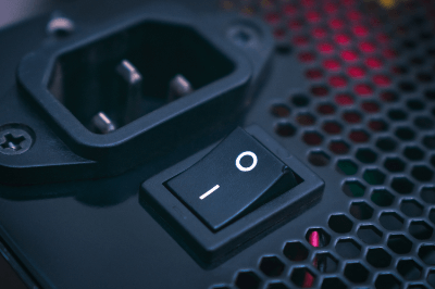
Rocker Switches are a type of manual switching device. Rocker switches are used to switch electrical circuits on and off by means of seesaw-like motion buttons.

Rocker switches can also be found in the home. For example, they are light switches or power buttons on devices that have a “0” and a “-” on both ends. They are used in a wide variety of equipment and facilities because of their simple construction.

Rocker switches are characterized by the click sound they make when operated, and the fact that they are clearly distinguishable between on and off, which reduces the possibility of accidental operation.

Uses of Rocker Switches

Rocker Switches are widely used as manually operated switches. Most of the switches we see and operate in our daily lives are rocker switches.

Specific examples of rocker switch applications include:

Rocker switches are used as operation switches for all kinds of products because of their simple structure and intuitive on/off operation.

However, there are many types of rocker switches. Each switch has different characteristics, such as operating voltage, durability, and water resistance.

Therefore, it is necessary to select the appropriate rocker switch for the intended use and operating environment.

Principle of Rocker Switches

The structure of a rocker switch is simple. The main components of a rocker switch are an operating button that moves like a seesaw, a sealing rubber, a spring, a fixed contact point, a movable contact point, and two connection terminals.

The operating button of the rocker switch is joined to the spring inside. In addition, between the switches operating button and the spring is a sealing rubber. The purpose of the sealing rubber is to protect the contact points from water, dust, and other substances that could affect the operation.

The spring of a rocker switch is bowed. The spring is connected to the operating button and the movable contacts.

When the switch is switched on, the movable contact side of the arched spring moves to press against the fixed contact side, and when the contacts make contact with each other, an electric current flows.

When the rocker switch is switched off, the bow-shaped spring moves so that the movable contact is pulled away from the stationary contact, stopping the flow of current. The advantage of this action is that it prevents the contacts from welding to each other as they are pulled apart.

The terms momentary and alternate are used for push-button switches such as rocker switches. These have different meanings in terms of how the switch moves when pressed.

1. Momentary Rocker Switch

Momentary Rocker Switches switch the electrical circuit only as long as it is pressed, and the contacts return to their original position when the hand is released. For example, the button that turns on the hot water in a kettle is a momentary type.

Momentary rocker switches function only while the button is depressed, and return to their original function when the button is removed from the hand.

2. Alternate Type Rocker Switch

Alternate Rocker Switches switch the electrical circuit when the switch is pressed, and the contacts are held until the switch is pressed again. For example, a switch that turns on the lights in a room is an alternate type.

An alternate rocker switch switches between ON and OFF each time the button is pressed.

Other Information on Rocker Switches

Number of Rocker Switch Terminals and Connection Methods

Rocker switches are simple in construction, but care must be taken in their selection. When selecting a rocker switch, it is necessary to consider the current and voltage supported, the resistance of the switch itself, its size, and its durability in relation to temperature and operating environment. Especially important to know is the number of rocker switch terminals and the method of connection.

Connecting rocker switches is easy if you simply turn them on and off. If it has two terminals, connect one to the power supply and the other to the device. If the rocker switch has three terminals, connect one to the power supply and one of the remaining two to the device. It is common practice to check the continuity of the circuit with a tester before connecting the terminals to distinguish between the terminals for the power supply and the terminals on the contact side.

Some rocker switches have four or more terminals. This is the case when a light bulb for lighting is built inside the rocker switch. The breakdown of the terminals is a circuit that feeds power to the device and a power ground for the bulb.

To connect a rocker switch with four terminals, connect the power supply to two terminals for a rocker switch with built-in lighting, connect one to the device, and then connect the ground wire for the lighting inside the rocker switch. Of course, note that the internal circuitry varies depending on the rocker switch used.

Check the electrical circuit in the instruction manual that comes with the rocker switch or use a circuit tester to check the continuity of the internal circuit before making wiring connections. If wiring connections are made blindly, the switch may not operate as expected, and in the worst case, the rocker switch or equipment may be damaged.

カテゴリー
category_usa

Electromagnetic Switches

What Is an Electromagnetic Switch?

Electromagnetic Switches
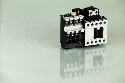
An electromagnetic switch is a switch that combines an electromagnetic contactor, which opens or closes an electric circuit by the action of an electromagnet, and a thermal relay, which interrupts the circuit when overloaded.

Most electromagnetic contactors have three main contacts corresponding to a three-phase power supply. In addition, there are several auxiliary contacts, which have a lower current rating than the main contacts. They are used to energize lamps and buzzers to indicate open/closed states or overloads, and for self-maintaining circuits.

Thermal relays detect the overcurrent that flows in the event of an overload and output a signal, but do not themselves have the function of interrupting the circuit. Therefore, they are used in combination with electromagnetic contactors that have a circuit-breaking function.

Uses of Electromagnetic Switches

Electromagnetic switches, unlike circuit switches, are used as a switching function for circuits with relatively large load currents, such as motors. They are mainly used in control panels. When selecting a switch, it is necessary to consider the allowable current, durability of switching, and ease of maintenance.

The most common application is in motor switching circuits. The method of providing an on/off button on the control panel is often used. Auxiliary contacts are used in circuits for self-hold circuits, lamp on/off, overload protection, etc.

For lighting applications, switching functions and overcurrent protection mechanisms are built into the control panel that manages all the lighting in a building.

Three-phase induction motors can be operated in forward and reverse by changing the phase order.

A reversible electromagnetic switch is available to switch between forward and reverse operation using two electromagnetic contactors; a mechanical interlock is incorporated to prevent the two contactors from being turned on at the same time. They are used when forward and reverse rotation is required.

Principle of Electromagnetic Switches

Electromagnetic switches consist of an electromagnetic contactor and a thermal relay.

1. Electromagnetic Contactor

The electromagnetic contactor consists of an electromagnet, a movable contact, a fixed contact, a coil, and a spring.

When the power is off, the movable and fixed contacts are separated by a spring. When the power is turned on, an electric current flows through the coil and a magnetic field is generated. The electromagnet is pulled by the magnetic field, the movable and fixed contacts contact each other, and current flows into the main circuit.

2. Thermal Relay

A thermal relay consists of a bimetal, which is a combination of two metals with different expansion rates, a heater, a push plate, and two connection terminals. When an electric current flows through the thermal relay, heat is generated from the heater in proportion to the magnitude of the current.

The heat causes the bimetal to bend and the push plate to be pushed. If a current greater than the set amount of current flows, the euphemism of the bimetal increases and the circuit is interrupted. This principle protects electrical equipment from overcurrents. For motor loads, it is common practice to set the current setting at 1.73 times the normal value or less.

When the thermal relay is activated, the operating circuit through the auxiliary contact of the electromagnetic contactor is interrupted. The current flowing through the electromagnet coil of the electromagnetic contactor is then turned off, interrupting the main contact circuit and stopping the motor, etc.

Other Information on Electromagnetic Switches

1. Difference Between Electromagnetic Switches and Relays

The difference between electromagnetic switches and relays is the value of current that can flow through the contacts. Relays are generally used only in control circuits. Relays are generally used only in control circuits, and even when they are used to operate a load, it is limited to a small motor or solenoid valve. The maximum contact capacity of a relay is about 5A.

Electromagnetic switches consist of a main contact that can carry a large current and an auxiliary contact that is used in a control circuit. The current that can flow through the main contact depends on the capacity of the electromagnetic switch, which can be 400 to 1,000A at maximum.

 2. Failure of Electromagnetic Switches

Electromagnetic switch failures can be broadly classified into two types. One is contact failure, which occurs when the contacts fail to make contact due to arcing caused by opening and closing, and the other is contact welding, which occurs when an excessive current flows through the contacts, causing them to stick together.

Contact failure occurs mainly due to deterioration over time. The higher the open/close current and the greater the frequency, the higher the probability of occurrence. Dust between contacts can also cause contact failure, which can be prevented by periodic cleaning.

Contact welding is often caused by forced deterioration and occurs when the load is too large or the wiring is faulty and rare shorts occur.

There are also coil failures. Coil failures include coil disconnections, shorts, and unfastening of the fixed iron core. Disconnection or short-circuit occurs when the control power supply voltage is wrong in the design stage. Coil failure can also occur due to age-related deterioration and can be avoided by periodic replacement, etc.

カテゴリー
category_usa

Zener Diodes

What Is a Zener Diode?

Zener DiodesA Zener diode is a diode consisting of an n-type semiconductor and a p-type semiconductor connected together, and has a relatively small reverse voltage and a stable voltage value. They are also called constant voltage diodes.

Normal diodes exhibit a rectifying effect in which the degree of conduction changes according to the polarity of the bias applied to both ends, and no current flows even when a very high reverse bias voltage is applied. However, a special type of diode called a Zener diode exhibits diode characteristics that allow a large amount of current to flow rapidly when a relatively small reverse bias voltage above a certain threshold is applied.

By utilizing the unique rectification characteristics of Zener diodes, a constant voltage can be maintained in the circuit.

Uses of Zener Diodes

Zener diodes are characterized by the fact that when a reverse bias above a certain value is applied, a rapid flow of current occurs and further voltage increases are suppressed. For this reason, they are used to maintain the voltage of unstable power supplies at a constant level and to protect circuits from surge currents.

For example, a Zener diode is connected in parallel with an unstable power supply with a reverse bias. As a result, if the voltage of the power supply is higher than the breakdown value of the Zener diode, a large current flows through the Zener diode, thus lowering the voltage and keeping the voltage across the circuit constant.

Principle of Zener Diode

The origin of the unique characteristics exhibited by Zener diodes is said to be related to two factors: the Zener effect and the avalanche effect. The former is a phenomenon (unique to Zener diodes) in which the depletion layer generated when a reverse bias is applied becomes thinner by intentionally creating a pn junction using a semiconductor with a high concentration of impurities, and at a certain threshold value, electrons jump through the depletion layer due to the tunneling effect, causing electrical conduction to occur.

The latter is a phenomenon in which electrons accelerated more strongly than those with a higher bias collide with semiconductor atoms, knocking out many carriers, and the electrons knocked out repeatedly collide with semiconductor atoms, knocking out more carriers, causing an electron avalanche and large current flow.

When the bias exceeds the threshold, the avalanche effect occurs, in which electrons that jump over the depletion layer due to the Zener effect cause a high reverse bias that results in a large current, which in turn causes a voltage drop, thus lowering the voltage to the threshold.

The voltage applied to the circuit is then kept constant, stabilizing an unstable power supply and protecting the circuit from external surges. Currently, the reverse breakdown voltage of these Zener diodes can be fabricated with extreme controllability, depending on the impurity concentration ratio and semiconductor process treatment.

A wide range of types and tolerances are available on the market, from 1 V to several hundred V, with narrow tolerances of ±0.05% depending on the voltage value.

Other Information on Zener Diodes

1. Series and Parallel Connection of Zener Diode

Series Connection
When connecting Zener diodes in series, pay attention to the value of the Zener current lz that flows. The maximum allowable current for the entire series corresponds to the smaller allowable current of the connected Zener diode. Therefore, use it within the smaller allowable loss.

Also note that if the Zener current for the Zener voltage specification is different for each diode, the voltage value will be different from the Zener voltage you want to obtain. The reason for this is that one of the Zener diodes will not have the specified Zener current value.

Parallel Connection
Zener diodes cannot be connected in parallel because it increases the allowable losses of the Zener diode. Note that when connected in parallel, the zener current may concentrate in whichever has the lower zener voltage and exceed the allowable power dissipation. 

2.Characteristics of Zener Diode

Temperature Characteristics
Temperature characteristics mean that the characteristics change with temperature. In the case of Zener diode, this temperature characteristic changes depending on the Zener voltage. The reason for this is the “tunneling effect” and the “avalanche effect.”

The temperature coefficient of the tunneling effect is negative, while that of the avalanche effect is positive. Therefore, if the Zener voltage is low, the Zener voltage will decrease as the ambient temperature rises. On the other hand, those with high Zener voltage are characterized by an increase in Zener voltage as ambient temperature rises.

A low Zener voltage here generally refers to a voltage lower than 5 V, while a high Zener voltage here generally refers to a voltage higher than 5 V. At around 5 V, the Zener phenomenon is caused by the combined effects of the tunneling and avalanche effects. At this time, the temperature characteristics are also about the same, making the Zener voltage less sensitive to ambient temperature.

Noise
In Zener diodes, the higher the Zener voltage, the higher the noise, and the higher the current, the lower the noise. To prevent noise, multiple elements with low Zener voltage should be connected in series. Noise can also be removed by connecting a capacitor in parallel with the Zener diode.

3. [By Application] How to Select a Diode

Although the characteristics and uses of Zener diodes have been described, there are various other semiconductor diode devices. Here is a supplementary explanation of the differences from other diodes and their characteristics.

One device that uses reverse characteristics is the TVS (Transient Voltage Suppressors) diode. Like Zener diodes, these diodes are used to provide over voltage protection, but unlike Zener diodes, TVSs are normally turned off and only turn on when a surge voltage is applied.

Schottky barrier diodes, which utilize a metal-semiconductor Schottky barrier, have even lower voltage values and are often used for rectifying applications with high switching speeds. PIN diodes with reduced terminal capacitance for RF (high frequency) applications are also used.

カテゴリー
category_usa

Load Cells

What Is a Load Cell?

Load Cells
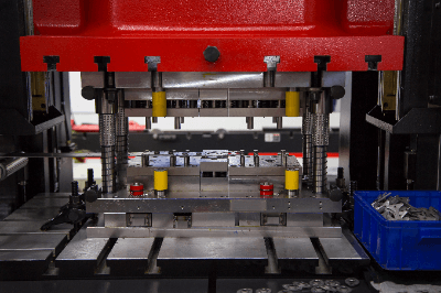
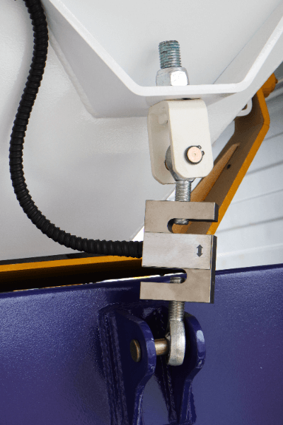
A load cell is a load transducer, a sensor that detects a load or force, converts it into an electrical signal, and outputs it. The output corresponding to the load or force is used to display or record the load, and may also be used for control.

In addition to the strain gauge type, which measures the deformation strain of an object, other types of load or force detection methods include the piezo piezoelectric type, metal thin film type, capacitance type, optical fiber type, vibration type, and magnetostrictive type.

The output of load cell is an analog or digital signal of voltage or current corresponding to the load. They are used to display and record the load on scales, measure loading capacity, and measure the load on material testing machines, and are also used to control plants.

Uses of Load Cells

Load cells are used in electronic scales, testing machines, flow meters, industrial scales, and various measuring instruments. For example, products for household use include scales, digital scales, and toilet seats for shower toilets.

In industrial applications, in addition to scales for heavy objects, they are often used in tensile testing machines, viscoelasticity measuring devices, presses, and yarn and film winding devices. They are also used to test the propulsion of jet engines, monitor the tension of mooring ropes on ships, measure torque in engines, monitor axle loads, measure wire tension in elevators, and weigh hoppers and silos.

Load cells are also used on the control rods of some aircraft. When the pilot applies force to the control stick, the computer detects the magnitude of the load and controls the airplane.

In industry, load cells are indispensable devices to measure the weight of products for quality improvement, productivity enhancement, and cost reduction, and to digitize the data for monitor display, good/fail judgment, printing, and data storage.

Principle of Load Cells

There are four main types of load cells: beam type, column type, S-shape type, and diaphragm type, depending on the shape of the member that is deformed when subjected to a load.

1. Beam Type

Beam type load cells measure the amount of beam deformation that occurs when a load is applied to the tip of a cantilever beam. It is used for platform scales.

2. Column Type

The column type measures the deformation strain in the compressive direction on the surface of a cylinder by applying a load to the cylindrical member. It is used for industrial applications such as tanks and hoppers. Multiple load cells are often used, in which case the load must be applied equally to each cell.

3. S-Shape

In the S-shape, a load is applied to both ends of an S-shaped member, and the deformation of the S-shaped member is measured and converted into a load. It is often used in tensile testing machines to measure tensile force.

4.Diaphragm Type

Diaphragm type load cells apply a load to the center of a diaphragm and measure the amount of deformation of the diaphragm. This type is generally used for load cells.

By changing the size and material of the cell member used, the scale of the load to be measured can be made larger or smaller. This makes it possible to measure loads over a wide range, from a few grams to huge forces in the ton range. In the measurement of minute loads, high-precision load cells capable of measuring on the order of mN have been developed and are used in the research and development of artificial muscles.

Methods for detecting the amount of deformation of materials that deform under load include strain gage, piezo piezoelectric, thin metal film, capacitance, optical fiber, vibration, and magnetostrictive methods.

In particular, the strain gage type is often used. A strain gage is attached to an elastic body called a strain generator, which expands or contracts due to minute deformation, resulting in a change in cross-sectional area, which in turn changes the resistance of the gage. Since this change is proportional to the load, the load applied to the strain gage is calculated from the change in resistance.

Other Information on Load Cells

1. Units of Load Cells

A load cell displays the measured value in SI unit of “force” “N” newton. Depending on the capacity of the Load Cell, “mN” or “kN” may be used.

“N” Newton is the value obtained by multiplying the mass by the acceleration of gravity. If the gravitational acceleration at the measurement location is known, the load cell can measure the mass (㎏). 

2. Accuracy of Load Cells

Generally, “accuracy” is not mentioned in the specifications of a load cell. The accuracy of a load cell is judged comprehensively based on the linearity, hysteresis, repeatability, and temperature effects described in the specifications.

When a predetermined voltage is applied to a load cell, it outputs a voltage proportional to the load, but this voltage is tiny, about 20mV at most. Since this small voltage is further divided into parts per million and measured, the measuring instrument used must be highly stable and accurate.

The accuracy of a measuring device using load cells must be judged comprehensively, including errors caused by individual load cells and indicators, temperature conditions, installation conditions, vibration, and other factors. To do so, the accuracy of the load cell, which is the detection part, and the accuracy of the indicator, are determined respectively, and the overall accuracy is calculated by the square root of the sum of their squares.

カテゴリー
category_usa

UV Sensors

What Is an Ultraviolet (UV) Sensor?

Ultraviolet (UV) sensors are sensors that detect ultraviolet light.

UV light is considered as being good for health when exposed to it in moderation and is used for health applications. Also, since ultraviolet rays have a sterilizing effect, sterilization equipment is one of the applications for ultraviolet rays.

However, since ultraviolet rays cannot be seen by the human eye, ultraviolet (UV) sensors are used in UV irradiation devices. In recent years, the sterilizing effects of UV light and UV-curing resins have been attracting attention, and UV irradiation devices are increasingly being used not only in industry but also in the home. There are various types of ultraviolet (UV) sensors in use, with some models outputting intensity and total amount.

Uses of Ultraviolet (UV) Sensors

Devices that artificially irradiate ultraviolet light are used in a variety of applications, from small health devices to industrial applications. Such devices are always equipped with ultraviolet (UV) sensors.

The purpose is to control the intensity of ultraviolet rays, as over-exposure to ultraviolet rays is harmful to the human body.

Industrial applications include the following uses:

  • Production of UV-curing resins
  • Inside semiconductor manufacturing equipment
  • Identification and printing of banknotes
  • Tanning salon machines
  • Athlete’s foot treatment equipment for the sterilizing effect of
  • Ultraviolet light
  • Air purifier

Principle of Ultraviolet (UV) Sensors

The main component of a UV sensor is a UV silicon photodiode. When the photodiode is irradiated with light containing ultraviolet rays, an electric current flows. Since the current value changes in accordance with the intensity of the ultraviolet light, the amount of ultraviolet light is detected by measuring the current value.

Photodiodes are characterized by different response speeds, etc., depending on their structure. There are Schottky junction, PN junction, and photoconductive types, each of which has its own characteristics, so they are selected according to the application.

Since diodes do not respond to sunlight, or incandescent light, sensors with optical filters are sold. There are also sensors that detect ultraviolet (UV) light by subtracting the visible light component from the difference between a high-sensitivity and a low-sensitivity Ultraviolet (UV) Sensor.

Some sensors use a photomultiplier tube instead of a photodiode as the UV light receiving element.

Other Information on Ultraviolet (UV) Sensors

1. The Ultraviolet (UV) Sensor Market

Ultraviolet (UV) sensors and other environmental sensors are attracting increasing attention, and the global market is expected to exceed 1.1 trillion yen. In the global market size surveyed for six types of industrial sensors, gas sensors account for the largest share, followed by magnetic sensors and ultraviolet (UV) sensors in third place.

The market for ultraviolet (UV) sensors is expected to grow to 1.4 trillion yen in 2024, and the overall demand for ultraviolet (UV) sensors is expected to grow as well.

2. Ultraviolet (UV) Sensors Used in Sterilization Applications

Taking advantage of the sterilizing effects of ultraviolet rays, UV sensors have recently been widely used in public facilities such as airports and commercial facilities such as restaurants. As a result, there are more opportunities for general consumers to come into contact with ultraviolet light generating devices than ever before.

As the demand for sterilization increases in places used by the public, it is necessary to measure whether the UV light is strong enough for sterilization, while at the same time making sure that no harmful wavelengths of UV light are leaking out. Ultraviolet (UV) Sensors will be important for this purpose. 

3. Flame Detection Using Ultraviolet (UV) Sensors

One product that utilizes ultraviolet (UV) sensors is a flame sensor that detects faint ultraviolet rays in flames. Applications include places where instantaneous fire detection is desired, such as clothing and bedding stores and smoking areas, where there is a risk of flames spreading. They are also used for flame detection in boiler burners.

Flame sensors are available in a variety of sensing methods, such as heat and infrared, but they present challenges, such as fire progression by the time they detect it. Ultraviolet (UV) flame sensors also have the challenge of potentially issuing false alarms depending on the machine generating the ultraviolet light. High-precision sensors are needed to detect fires quickly.

カテゴリー
category_usa

Sneeze Guards

What Is a Sneeze Guard?

Sneeze Guards

With the outbreak of the new coronavirus, the use of sneeze guards as a countermeasure against coronavirus infection is increasing.

Based on the recognition that coronavirus infection is caused by saliva droplets, sneeze guards are employed to block saliva droplets that fly mainly when people cough or talk. Accordingly, sneeze guards are used at places such as cash registers in stores, or offices, places where people come in face-to-face contact with each other.

Since they can physically block droplets, they provide greater droplet control and peace of mind than masks alone. Many of the sneeze guards currently on the market are transparent, which is an advantage because it allows people to see each other’s faces and situations even when being separated by the partitions, making it possible to have smooth conversations.

Places Sneeze Guards Are Useful

Sneeze guards have been introduced to prevent infectious diseases and are often used in offices, various sales outlets, bank and government offices, etc., where it is necessary to meet with many people, and are mainly installed on desks.

In addition, the sneeze guards are recommended for use in restaurants where removing masks is required and the spread of droplets from eating and drinking is a concern. These types of close contact situations are the partitions’ specialty.

In addition to full-surface panels, there are also panels with a partially open window for receiving tickets, money, etc.

Precautions for use of Sneeze Guards

Since droplets remain on the panel after use, it is advisable to disinfect the panel frequently after use by wiping it with wet wipes, etc. Whatever you use should be disposed of to avoid the infected droplets from spreading.

Acrylic, PET resin, and rigid polyvinyl chloride are used as materials for sneeze guards and PET resin and rigid polyvinyl chloride are resistant to alcohol and sodium hypochlorite used for disinfection. However, acrylics may develop minute cracks when wiped with highly concentrated alcohol, so use caution.

Also, since flammable plastics may be used, please read the precautions and avoid using the product in areas where fire is present, such as around stoves or lit cigarettes.

Effectiveness of Sneeze Guards

Saliva from coughing or talking can be splashed over a wide area, with an average distance of 1 to 2 meters if not wearing a mask and no sneeze guard is used.

When we tested how much of the droplets could be prevented from spreading with a sneeze guard, we confirmed that when a person coughs with the panel 120 cm from the floor (about the mouth height of a person sitting on a chair), some fine droplets spread beyond the partition panel to the person directly in front, diagonally in front, and to the person beside him. In the case of a panel about 140 cm high (about enough height to cover the seated person’s head), the droplets were almost nonexistent on those around the panel. In other words, panels at least as high as the head should be placed to prevent splashing.

Characteristics of Sneeze Guards by Material

There are two types of sneeze guards: foldable and assembled. The characteristics vary greatly depending on the material of the panel part. Typical materials and characteristics are as follows.

Polystyrene foam used for building boards, fish boxes, etc. is a very inexpensive, lightweight, strong, and hygienic material that can be disinfected with alcohol, making it a good choice. However, it is opaquely colored white or black and is not transparent. Therefore, it is not suitable for use in places where face-to-face interaction is required, as the view is obstructed.

Like styrene foam, corrugated fiberboard is inexpensive and lightweight. It is also easier to dispose of than other materials. On the other hand, like styrene foam, it is not suitable for use in places where face-to-face interaction is required because it blocks the view.

Acrylic material, originally used as acrylic glass and acrylic cases, is the most robust material because of its thickness. It is also highly permeable and has a luxurious feel, making it suitable for face-to-face customer service situations.

Plastic materials such as PET are relatively transparent and lightweight, are less likely to break, and are easier to handle than acrylic materials.

On the other hand, vinyl curtains are sometimes used for the same purpose as sneeze guards. Since they are easy to install, they can be used in different ways depending on the location and situation to be used.

Criteria for selecting Sneeze Guards and future prospects

The following five points are the criteria for selection.

  1. Location and situation of use
  2. Type of the splash prevention panel
  3. Precautions for use
  4. Size of the panel
  5. Material of the panel

Demand is expected to continue to increase as a means of preventing the spread of infectious diseases. Some companies have more than doubled their sales of plastic and acrylic panels, while others have increased production by as much as 50%, which is having an impact on raw material manufacturers. A survey conducted at a certain exhibition showed that about 60% of companies have introduced sneeze guards, indicating that many companies feel the need for the panels and that demand will further increase in the future. Therefore, it is expected that this will also continue to have an impact on raw material manufacturers, manufacturers, and sales distribution companies involved in the panels.

This product can be a great business opportunity for both buyers, manufacturers, and distributors.