カテゴリー
category_usa

Power MOSFETs

What Is a Power MOSFET?

Power MOSFET
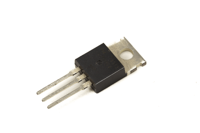
Power MOSFET is a generic term for MOSFET devices for high-power applications. MOS stands for Metal Oxide Silicon.

In the past, bipolar transistors with base, collector, and emitter terminals were the main switching devices. In comparison, MOSFETs have faster switching speed, lower voltage, and lower on-resistance, enabling low-loss operation.

Uses of Power MOSFETs

Power MOSFETs can be used as a substitute for bipolar power transistors in circuits that conventionally use bipolar power transistors. In particular, Power MOSFETs have lower switching losses than bipolar power transistors.

The high on-resistance and low breakdown voltage of MOSFETs and the difficulty of applying them to high-power circuits have all been overcome by recent technological innovations such as the planar-gate double diffusion structure, trench gate structure, and super junction structure, and now power MOSFETs have become the most popular power transistor in the world.

MOSFETs are now the mainstay of the power transistor world.

Principle of Power MOSFET

Power MOSFETs, by their very principle, operate only with a large number of cores (electrons for n-type transistors and holes for p-type transistors). Therefore, they are not affected by the minority carrier like the bipolar type, which has been the mainstay of power transistors in the past. Fundamentally, they have a higher input impedance than junction-type FETs, so recent Power MOSFETs are more difficult to break than conventional ones.

Power MOSFETs can be broadly classified according to their gate structure and drift layer structure, and the three major structures that have prevailed in recent years are described below.

1. D-MOS Double-Diffused MOSFET Structure

This structure achieves high breakdown voltage by double-diffusion channel formation, resulting in a high-performance Power MOSFET with high integration, low ON-resistance, and low loss.

Specifically, in the case of an N-channel MOSFET, a low-concentration p-type layer and a high-concentration n-type layer are formed by double diffusion on an N-substrate epitaxial layer.

P-channel MOSFETs are also available, but the mobility of holes is smaller than that of electrons, resulting in higher on-resistance and degraded characteristics.

2. Trench Gate Structure

The trench gate structure is a U-groove gate structure in which the channel is formed vertically to achieve higher integration and lower ON-resistance. However, this structure is used for low-voltage Power MOSFETs.

The unit cell area is reduced by U-grooving the gate.

3. Super Junction Structure

This is currently the best Power MOSFET available, except for the change in substrate material. The periodic vertical p/n structure called super junction is formed in the drift layer to achieve ultra-low ON-resistance below the silicon limit of conventional Power MOSFETs.

Other Information on Power MOSFETs

Scope of Use of Power MOSFETs in the Market

Power MOSFETs are used in high-power power supply applications at relatively low cost due to their low cost and high reliability on silicon substrates. However, when it comes to high-power power supply applications that handle several kVA, the on-resistance increases to several ohms, which significantly increases losses and takes them out of the usable range.

Currently, the semiconductor devices mainly used in this area are IGBTs (Insulated Gate Bipolar Transistors) or SiC Power MOSFETs, which are used in combination with bipolar transistors to suppress the increase in on-resistance in the high-current region of MOSFETs.

The SiC power MOSFET is a power MOSFET with a bipolar transistor and a SiC power MOSFET.

SiC Power MOSFETs are characterized by the use of SiC compound semiconductors, which are wide bandgap crystals, as the substrate material, and by the dramatic improvement in breakdown voltage. MOSFETs are used for high power and high speed switching power supply applications at several 100KHz.

IGBTs are not suitable for high-speed switching power supplies due to their device structure, while SiC Power MOSFETs are used because of the relatively high cost of SiC substrates (due to wafer size limitations and other factors). Nevertheless, Power MOSFETs on silicon substrates, which are relatively inexpensive and easy to use, will continue to be used in the mid- to low-power range, with improvements in characteristics and cost, unless new devices emerge that can replace them.

カテゴリー
category_usa

Touch Switch

What Is a Touch Switch?

A touch switch is a switch that is turned on and off by touching the screen with a user’s finger or pen.

Various detection methods are available, such as capacitive, resistive, and infrared, and are used according to the application. Compared to buttons and keys, switches can be placed on a flat surface and are superior in design, so they are widely used in operation panels of AV equipment and industrial equipment, and in operating units of public equipment.

It was also a pioneer in touch operation even before the appearance of touch-operated products such as smartphones and tablets. Recently, smaller and thinner touch switches are required to accommodate the miniaturization of mobile devices and the IoT.

In the development of touch switches, reliability and cost performance, as well as improved operability, have become important factors.

Uses of Touch Switches

Touch switches that we often see in our daily lives are mainly intended for human operation. Examples include pushbuttons for electrical appliances in homes, elevators in shopping malls, and automatic doors. Recently, capacitive touch switches that are activated simply by touching the screen, such as smartphones and touch panels, are becoming the mainstream.

Touch switches are also widely used inside industrial robots and machine tools. At hazardous sites such as factories, they also serve as safety devices to prevent workers from entering or being pinched and to detect damage to tools.

Principle of Touch Switches

As the name suggests, touch switches are operated by touching. The most appropriate type of touch switch should be selected according to the operating environment and purpose.

1. Capacitive Touch Switch

Capacitive touch switches utilize the fact that the human body is a conductor of electricity. When a finger approaches the surface of the switch, the capacitance changes, and the switch turns on or off by detecting this change. This technology is often used in touch screens for smartphones and tablets.

2. Resistive Touch Switches

Resistive touch switches have two conductive layers with an insulating layer in between. When the user touches the surface, the two conductive layers come into contact and an electric current flows. The change in this current is detected and the operation of the switch is controlled.

3. Infrared Type Touch Switch

Infrared touch switches use an infrared sensor to detect the proximity of the user’s hand or finger. The sensor emits infrared light and detects the reflected light. As the hand or finger approaches, the amount and angle of the reflected light changes, and the switch operates based on this change.

Types of Touch Switches

Touch switches are used in many situations, and their range of application is expanding every day. However, not all touch switches are the same.

It is important to select the most appropriate type depending on the specific application and environment.

1. Low Power Type

This is a touch switch with extremely low power consumption. Suitable for battery-powered portable devices.

2. High Durability Type

This type can maintain high performance for a long period of time. Often used in industrial applications and public facilities.

3. Multi-Point Type

This type of touch switch can detect multiple touch points simultaneously. Often seen in smartphones and gaming devices.

4. Other

Types that operate stably even in environments with a lot of moisture or dirt are useful in kitchen appliances and medical equipment. Some types can also be customized for specific applications or special environments. They are used in multifunctional operation panels and special industrial applications.

カテゴリー
category_usa

Board-to-Board Connectors

What Is a Board-to-Board Connector?

Board to Board Connectors

Board-to-Board Connector is a connector used for high-density mounting of printed circuit boards.

Among these connectors, those that are designed to allow the connected connectors to move in three directions (pitch, row-to-row, and mating) or to move in either direction to suppress the effects of mating misalignment are called floating connectors.

By combining a socket and a plug, the connector can move in the x-y-z three-dimensional direction, making it less susceptible to pry (shock) and misalignment.

Applications of Board To Board Connector

Board-to-Board Connectors are used in response to the recent trend toward miniaturization of equipment, and can directly connect boards together. Because of this advantage, Board-to-Board Connectors have a wide range of applications, including computers, portable information devices, digital TVs, automobiles, and industrial machinery and infrastructure.

In recent times, as electronic devices have become increasingly sophisticated, demand for more advanced and precise Board-to-Board Connectors has been increasing.

Principle of Board-to-Board Connector

Board-to-Board Connectors use pins and sockets to connect boards. The function of the pins and sockets is to connect and separate the boards through electrical contact and mechanics.

This ability to separate and join allows equipment to be configured as a unit, which is an advantage over permanent connections such as soldering or screwing. The structural design of the product and the ease of mass production enable a reduction in the total cost of ownership. It also improves maintainability, such as parts replacement and inspection, leading to stabilization of performance and quality.

How to Select Board-to-Board Connector

Board-to-Board Connectors are available in two types: the stacked type, in which the boards are stacked top to bottom, and the stand-up type, in which one of the boards is used standing up for connection. Since the shape of the connector changes depending on the direction in which the boards are connected, first consider which direction you wish to connect the boards.

There is also a bottom-entry type in which the pins penetrate from the underside of the connector. While they have the disadvantage of low mounting density, the distance between boards can be set freely. Because of this characteristic, they are used in products that have heat-generating components on separate boards.

When selecting Board-to-Board Connectors, it is necessary to confirm that the current value, withstand voltage, insulation, etc. meet the circuit specifications. In the case of circuits that require micro level and high reliability, it is also important to check the material.

Other Information on Board-to-Board Connector

1. Advantages of Board-to-Board Connector

Board-to-Board Connectors are used when additional circuits can no longer be placed on the printed circuit board during the design process. Other times, when several boards with slightly different functions are combined into one board, the boards with different functions are treated as optional boards.

The Board-to-Board Connector enables the use of a single type of board to realize the functions of multiple products by installing and removing optional boards. Normally, cables are used to connect boards to boards, but when boards are connected by cables in this way, the space occupied by the board in the equipment becomes large.

Board-to-Board Connectors are useful in meeting the need for miniaturization, since this is an obstacle when miniaturizing products. This connector can be used when circuits do not fit on a single board, when boards of different sizes are mounted, or when boards need to be joined together because of the miniaturization of the product.

2. Cautions for Board-to-Board Connector

When joining boards, it is necessary to make sure that the joints of the boards match each other in terms of the number of pins, etc. In addition, connectors only have the function of joining boards together and do not have a large mechanical support force for the boards.

Therefore, a separate mechanism to support the board with screws or other means is required. Although this connector facilitates maintenance of the board, careful handling is required to prevent excessive force from being applied to the board and damaging it when the connector is removed.

カテゴリー
category_usa

Tilt Sensors

What Is a Tilt Sensor?

Tilt Sensors

Tilt Sensor is a device that detects the inclination of an object to be measured.

It measures the inclination from the horizontal position and detects the tilt, angle, or slope of the object to be measured. 

It measures the tilt from the horizontal position with respect to gravity and displays the tilt, angle, or gradient of the object. Tilt Sensors are also called Angle Sensors. Tilt Sensors strictly refer to the tilt detection part only, and there are other types of Tilt Sensors, such as inclinometers, to which electronic devices are added to adjust input and output.

Uses of Tilt Sensors

Tilt Sensors are used for tilt detection and posture control. Specifically, they are used to maintain the level of construction equipment beds, detect the tilt of cranes, and adjust the illumination angle of automobile headlights. They are also used to check the level of land and rooms, and to automatically rotate smartphone screens.

Strictly speaking, Tilt Sensor refers only to the element that detects inclination, and when an electronic device that adjusts input and output is added, it is called an inclinometer. However, devices that include an input/output device and an arithmetic device are also conventionally called Tilt Sensors.

Principle of Tilt Sensor

Tilt Sensors are devices that detect inclination by generating an electrical output when the object being measured is inclined. Tilt occurs in the uniaxial, biaxial, and triaxial directions, so it is important to select a Tilt Sensor according to the number of axes of inclination to be detected.

In addition, Tilt Sensors have changed from the switch form that switches on and off when an inclination is detected, which was often used in the past, to those that combine sensing technology, which have become mainstream in recent years. The methods used to detect the tilt of Tilt Sensors include the electro-electrolytic and MEMS, which have been used since the early days. In recent years, the MEMS type has become the mainstream in terms of accuracy and response time.

1. Electrolytic Tilt Sensor (Electrostatic Tilt Sensor)

The electrolyte type Tilt Sensor uses the property of a liquid surface to always be horizontal to detect the tilt of the liquid as a change in electrostatic capacitance. Specifically, the sensor consists of a cylindrical body with an internal cavity in which electrolytic solution (conductive liquid) is sealed at a depth of about half its length, and electrode plates facing each other in the longitudinal direction.

In other words, the corresponding electrodes are half submerged in the electrolyte in the longitudinal direction. When the cylindrical body is tilted with voltage applied between the electrode plates and the electrolytic solution in the cavity is kept horizontal on its axis in the longitudinal direction, the internal resistance in the circuit changes due to the difference in the portion of the opposite electrode that is immersed in the liquid. The tilt detection of the electrolyte Tilt Sensor is performed by detecting this change in the internal resistance of the circuit and converting it to an angle.

However, it has the disadvantages of a relatively slow response time and a tendency to be affected by vibration of the liquid surface. The electrolyte type Tilt Sensor can detect tilt in two axes by arranging two pairs of electrodes orthogonally to each other.

2. MEMS (Micro Electro Mechanical Systems) Tilt Sensor

The MEMS Tilt Sensor is an inclination sensor that utilizes micro-electromechanical system technology. The MEMS Tilt Sensor consists of a pair of fixed electrodes and a spring-loaded movable electrode between the fixed electrodes.

When the MEMS Tilt Sensor is tilted about the support direction of the fixed and movable electrodes, the fixed electrodes do not move, while the movable electrodes move in the direction in which the sensor is tilted. In other words, the capacitance between each fixed and movable electrode changes. This change in capacitance is detected and converted to an angle.

If movable electrodes are installed orthogonally to the XY direction and each is sandwiched between a pair of fixed electrodes, inclination in two axial directions can be detected.

3. Other Methods

Other methods used in Tilt Sensors include the pendulum type and the quartz crystal type.

Pendulum Tilt Sensor
Pendulum Tilt Sensors have a pendulum and a sensing element such as a magnetoresistive element inside the body. The pendulum Tilt Sensor detects changes in the magnetic field caused by the movement of the pendulum when the main unit is tilted, and calculates this into an angle of inclination.

Quartz Tilt Sensor
The Quartz Crystal Tilt Sensor is a highly sensitive Tilt Sensor that utilizes the characteristics of a quartz crystal. A cantilever made of processed quartz crystal and a holding part are fixed at one end facing each other, and an electrode is provided on each of the cantilever and holding part.

When the sensor is tilted, the cantilever deflects while the holding part does not. Because the cantilever deflects, the distance between the electrodes changes and the capacitance also changes. The capacitance is measured as a change in frequency, which is how the quartz tilt sensor works. The conversion from capacitance to frequency is achieved by combining the Tilt Sensor with a quartz crystal and a transmitter circuit.

Other Information on Tilt Sensors

Acceleration Sensor

Similar to the Tilt Sensor, the Acceleration Sensor is a sensor that detects tilt. The Tilt Sensor outputs the sensor output itself with information on the angle of inclination. Because of its low frequency fluctuation, the tilt sensor is effective for measuring the tilt angle in slow motion or in a stationary state. Acceleration sensors, on the other hand, detect acceleration applied to an object.

Using Newton’s law of motion, which states that acceleration acting on an object is proportional to external force, acceleration sensors are used to measure acceleration itself or to detect the application of external force. Since acceleration itself can be detected, it is used in gravity and seismic measurements. Since it can also detect the application of external force, it can detect movement in front-back and left-right directions in addition to the direction of gravity, such as tilt, vibration, movement, impact, and fall. Compared to the Tilt Sensor, it has a wider frequency bandwidth and can also measure fast movements.

Because of these differences, Tilt Sensors are used, for example, to prevent cranes and construction vehicles from tipping over. Acceleration sensors, on the other hand, are used, for example, in applications that change the vertical and horizontal display of a smartphone to match the environment in which it is used.

カテゴリー
category_usa

Signal Converter

What Is a Signal Converter?

Signal Converters

A signal converter is a device that transforms electrical signals from various sensors into industrial current signals.

Sensors gather information, such as temperature, load, or the number of revolutions of a machine’s rotating shaft, and convey it as measurement data. This data is then transmitted to control equipment, which uses it to output commands and control the system.

Signal converters adapt the electrical signals from sensors into a format compatible with control equipment. They also isolate abnormal electrical signals from sensors to prevent damage to downstream control devices.

There are many types of signal converters, each playing a crucial role in transmitting sensor information to control systems and devices.

Uses of Signal Converters

Signal converters are essential in electronics that utilize various sensors. Their applications range from industrial manufacturing machinery to laboratory instruments and measurement devices.

They are also employed in factory processing furnaces for heating or cooling, in equipment for controlling turbine, spindle, and shaft speeds, in load measurement for machine tools, and test equipment.

Principle of Signal Converters

The operation principle of signal converters varies by type:

1. Isolator

Isolators disconnect signals from the electrical circuit between the sensor and control circuit, preventing signal routing issues, protecting equipment, reducing noise effects, and facilitating signal exchange between different manufacturers’ equipment.

2. Pulse Transducers

Pulse transducers convert signals from proximity sensors into analog signals for rotational speed control. They transform pulse signals detected by proximity sensors into analog signals for output.

3. Couple Transducers

Couple transducers, used for temperature measurement, convert the electromotive force (emf) signals from thermocouples into analog signals for output.

4. Load Cell Transducers

Load cell converters transform the resistance changes in strain gauges, caused by force-induced deformation, into analog electrical signals for measuring force magnitude.

Other Information on Signal Converters

Signal Converter Cautions

It’s crucial to consider noise countermeasures for signal converters. They should be installed away from high-frequency and surge-generating devices and, where necessary, supplemented with surge absorbers and noise filters to mitigate interference from motors, transformers, solenoids, and magnet coils.

カテゴリー
category_usa

Torque Sensors

What Is a Torque Sensor?

Torque Sensors

Figure 1. Appearance of a Torque Sensor

A torque sensor is a device that measures torque, the force that causes a shaft to rotate, as illustrated in Figure 1.

It converts the slight twist of a shaft under torque into a measurable output, displaying the torque value. Torque sensors are crucial in various scenarios requiring torque measurement, including torque management in production lines and evaluating the performance of industrial machinery.

While it may also be referred to as a torque gauge or torque meter, there are no strict naming conventions. This article will use “torque sensor” consistently regardless of application.

  • Torque Sensor
    A device used in electric bicycles and robots to control motors or robots based on detected torque.
  • Torque Gauge
    A device for measuring the tightening torque with tools like screwdrivers and instantly checking the torque value on a display.
  • Torque Meter
    A device for assessing motor torque in motor testing setups.

Uses of Torque Sensors

Torque sensors are commonly used in electrically powered bicycles, where they detect the pedal force (torque) applied by a cyclist. The motor then provides the necessary assistance based on this torque, easing the pedaling effort.

In industrial settings, torque sensors are vital in quality control and research testing.

1. Quality Control

Torque sensors are utilized mainly in:

  • Spot Checks
    Examining how tightly container caps are sealed during production.
  • Periodic Inspections
    Ensuring electric screwdrivers on the production line operate within expected parameters before work commences.

2. Test and Research

In testing and research, torque sensors are mainly employed in:

  • Strength Measurement
    Assessing test materials and components for torsional strength.
  • Motor Performance Evaluation
    Determining motor performance under various loads.
  • Rotational Torque Measurement of Machinery
    Measuring the torque in machinery, such as rotary printing press rollers, to find optimal operating conditions.

Principle of Torque Sensors

The operation of torque sensors involves the following steps:

  1. A torque is applied to the shaft.
  2. This torque induces torsion/strain on the shaft.
  3. The shaft’s torsion/strain is measured.
  4. The torque on the shaft is calculated from this measurement.

The measured torsion/strain is converted into an electrical signal, often amplified by an amplifier for easy interpretation and displayed by an A/D converter. Some sensors come with a display for immediate torque reading.

Types of Torque Sensors

Various methods exist for measuring shaft torsion and strain, with the following four being prevalent in current torque sensors:

1. Strain Gauge Type Torque Sensor

2060_Torque-Sensors_トルクセンサー-2.png

Figure 2. Axis of Strain Gauge Type Torque Sensor

This method employs strain gauges to measure shaft strain due to electrical resistance changes during expansion and contraction. As depicted in Figure 2, tensile and compressive stresses occur at ±45° angles when torque is applied, which is measured by strain gauges.

2. Capacitive Torque Sensor

This method gauges shaft strain through capacitance changes between two electrodes on the shaft, affected by its warping.

Due to its simpler structure and shorter shaft requirement, it’s widely used in robotic torque sensors.

3. Magnetostrictive Torque Sensor

Here, shaft strain is measured by detecting inductance changes in a coil due to the inverse magnetostrictive effect when torque is applied, altering the magnetic permeability.

Advantages include non-contact measurement capabilities, making it suitable for rotating shafts without compromising shaft integrity.

4. Optical Torque Sensor

An optical sensor measures shaft strain by detecting changes in light amount due to emitter and receiver displacement under torsion or distortion.

Other Information on Torque Sensors

Products With Built-in Torque Sensor

Advancements in technology have led to the miniaturization of torque sensors, integrating them into industrial products. Here are examples:

1. Motor With Built-in Torque Sensor
Integrates a motor, reduction gear, and torque sensor for compactness and accurate torque measurement for smoother operation and safety enhancement through human contact detection.

2. Torque Sensor for Robots

2060_Torque-Sensors_トルクセンサー-3.png

Figure 3. Torque Sensor Built Into the Cooperative Robot

Articulated robots with integrated torque sensors, especially in cooperative robots, enable precise control of force and detection of human or obstacle contact.

カテゴリー
category_usa

Hydraulic Valves

What Is a Hydraulic Valve?

Hydraulic Valves

A hydraulic valve is a device used to control the flow of fluid in a hydraulic system.

They are used in machines and equipment to transmit and control power. Hydraulic valves control the operation of a system by adjusting the pressure, flow, and direction of fluid according to specific conditions.

These devices are widely used in a variety of industries, including automotive braking systems, construction machinery, and factory production lines. These valves stabilize machine operation by providing efficient and accurate control.

Applications of Hydraulic Valves

The main applications of hydraulic valves are as follows:

1. Construction Machinery

In construction machinery such as bulldozers, excavators, and cranes, hydraulic valves are used to control drive systems and braking. This provides precise control of machine operation and improves safety and efficiency.

2. Agricultural Machinery

In agricultural machinery such as tractors and combines, hydraulic valves are used to control the operation of steering, lifting, and traction devices.

3. Factory Machinery

In factory production lines and machinery, hydraulic valves are used to control movement. This ensures proper regulation of machine movement and pressure to make the production process more efficient.

4. Industrial Machinery

In industrial machinery such as presses, injection molding machines, and robotic arms, hydraulic valves are used for precise motion control.

5. Aircraft and Ships

In aircraft and ships, hydraulic valves are used to control flight control systems, landing gear, hydraulic doors, etc.

6. Vehicles

Hydraulic valves are incorporated in the braking systems of cars and trucks. This ensures that the proper braking force is applied and that the driver can safely control the vehicle.

7. Pressure Control Systems

Hydraulic valves are sometimes used to control pressure. Examples include automotive suspension systems and hydroforming processes.

Principle of Hydraulic Valves

Hydraulic valves use hydraulic pressure to drive valves. Hydraulic drives use the incompressibility of oil to drive a machine or system. When oil is subjected to pressure, the force generated by the oil is transmitted to the machine or actuator to control its motion or force.

When oil is pressurized, the pressure is transmitted evenly throughout the liquid, effectively transferring the force received by the oil to the actuator. The principle of hydraulic drive is also based on Pascal’s principle. Pascal’s principle states that when a fluid is in a closed container, the pressure on the fluid is evenly distributed, and that a small force can be applied to produce a large force by using the pressure of the fluid.

In other words, hydraulic drives can generate large forces and torques by taking advantage of the incompressibility of fluids. This allows them to lift heavy loads and perform tasks that require high torque. Hydraulic valves are therefore particularly suited for controlling highly viscous fluids that require high forces and torques.

Types of Hydraulic Valves

The main types of hydraulic valves are as follows:

1. Switching Valve

A switching valve switches the fluid between the input and output ports. By supplying fluid to different ports, the operation of the system can be switched.

2. Pressure Control Valve

Pressure control valves are used to control the pressure in a system. They help to set a specific pressure value, prevent the system from overloading, and ensure the required operation.

3. Flow Control Valve

Flow control valves are used to control fluid flow. They can ensure a specific flow rate and regulate the speed and operating stability of the system.

4. Directional Control Valve

Directional valves are used to control the direction of fluid flow. They help to change the operating direction of cylinders and actuators.

5. Quasi-Safety Valve

Quasi-Safety Valves are used to prevent abnormal pressure build-up in a system and open automatically when a specific pressure is exceeded.

カテゴリー
category_usa

Vibration Sensors

What Is a Vibration Sensor?

Vibration Sensors

Vibration Sensors are sensing elements used to measure the vibration state of a machine or object.

Vibration Sensors are necessary to understand and monitor the vibration state of a machine. There are three indices that represent the vibration of an object: acceleration, velocity, and displacement. Vibration Sensors measure these physical quantities and convert them into electrical quantities such as voltage and current.

In general, Vibration Sensors are available in two configurations: contact and non-contact. Depending on the physical quantity being measured (acceleration, velocity, displacement) and the conditions of the object, these two types of Vibration Sensors must be used in different ways. In addition, the magnitude and frequency range of the object being measured, as well as the measurement environment, must be taken into consideration when selecting a detailed Vibration Sensor to improve measurement accuracy.

Applications of Vibration Sensors

Vibration Sensors are used in production facilities and research and development. In production facilities, Vibration Sensors are useful for preventive maintenance to detect equipment failures and damage at an early stage. The use of sensors can prevent the occurrence of huge repair costs and loss of production efficiency due to breakdowns and damage.

In recent years, small Vibration Sensors have been used in production facilities, mostly for the purpose of machine diagnostics and predictive maintenance using IoT technology. An example of the use of Vibration Sensors in the field of research and development is the measurement of vibrations in product testing and durability testing.

Vibration Sensors are also used to evaluate passenger comfort, particularly in the automotive industry. Other applications in the field of industrial equipment range from electrical equipment and automobiles to production robots.

Principle of Vibration Sensors

As mentioned above, there are two types of Vibration Sensor configurations: contact and non-contact. Contact Vibration Sensors are used to measure acceleration, while non-contact Vibration Sensors are used to measure velocity and displacement.

This section introduces the principle of each type of Vibration Sensor suitable for various vibration (acceleration, velocity, and displacement) measurements. 

1. Contact Type: Acceleration-Sensing Piezoelectric Sensors

Piezoelectric sensors utilize the piezoelectric effect that occurs in piezoelectric materials. The piezoelectric effect is a phenomenon in which a piezoelectric material (piezoelectric element), such as a single crystal of quartz, generates an electric charge on its surface when subjected to a force. The piezoelectric effect produces an electrical signal corresponding to the acceleration.

2. Non-Contact: Laser-Doppler Sensor with Velocity Detection

Laser-Doppler sensors are sensors that utilize the Doppler effect. A laser beam is emitted from the Vibration Sensor to a vibrating object, and the frequency change of the laser beam reflected from the vibrating object is converted into a voltage as a change in velocity.

3. Non-Contact Type: Displacement-Detecting Capacitive Sensor

Capacitive sensors are sensors based on the principle of measuring the capacitance between the sensor and the object to be measured and calculating the distance. When the distance between the sensor and the object to be measured changes, the capacitance value changes, thereby measuring the displacement of Vibration Sensor.

Other Information on Vibration Sensors

1. Detecting Elements of Vibration Sensors

The detection element of mechanical vibration is the temporal change in the magnitude of a quantity representing the motion or displacement of a mechanical system. In many cases, the vibration alternates between a state that is greater than or less than the average or reference value. In general, this vibration is composed of three elements: amplitude, frequency, and phase.

In particular, vibration that repeats at regular intervals is called harmonic vibration and consists of a single frequency. In such cases, displacement, velocity, and acceleration are as follows. By differentiating the displacement, the velocity can be derived, and by differentiating the velocity, the acceleration can be derived.

  • Displacement d = Dsin (ωt + Φ)
  • Velocity v = Vcos (ωt + Φ)
  • Acceleration a = – Asin

D: single amplitude, ω: each velocity ω=2πf, f: frequency f=1/T, T: period (seconds), Φ: initial phase.

The types of Vibration Sensors used to detect this harmonic vibration include Acceleration Sensors (piezoelectric type), Velocity Sensors (electrokinetic type), and Non-contact Displacement Sensors (eddy current type). Among these, the piezoelectric type acceleration sensor in particular is characterized by its ability to cover a wide frequency range. 

2. Usage of Vibration Sensors

As an example, we will explain how to use a piezoelectric Vibration Sensor, which is used for vibration monitoring. Piezoelectric Vibration Sensors utilize the piezoelectric effect, and when an external force is applied, they generate and output an electric charge proportional to that force. Piezoelectric Vibration Sensors with charge output are particularly advantageous for miniaturization.

It is important to fix the sensor firmly with stud bolts to ensure it closely adheres to the non-measured object. If the sensor is not firmly attached, it may exhibit distinctive filter characteristics with peculiar attenuation patterns in the frequency response, thus making accurate measurements impossible. Other methods include using adhesives or magnets to fix the sensor.

Frequency analysis is widely used to analyze data detected by Vibration Sensors. Frequency analysis is a method of examining the frequency components and intensity of the measured waveform, and can provide an indicator to determine whether the vibration of an object is in normal operating condition or not.

カテゴリー
category_usa

Photoelectric Sensors

  • What Is a Photoelectric Sensor?

Photoelectric SensorsA Photoelectric Sensor is a sensor that detects light.

The sensors use the properties of light to detect the surface shape and condition of the object being measured, as well as its constituent materials.

They are suitable for pre-shipment inspection and nondestructive testing equipment because they can detect surface shape and constituent substances without contact.

They are characterized by their ability to measure long distances, short response time, and high resolution. Detection methods include transmissive, retro-reflective, and diffuse-reflective types.

Uses of Photoelectric Sensors

Photoelectric sensors are used in a wide range of applications from consumer products to industrial equipment. Examples of applications are as follows:

  • Inspection in production plants for food, consumer products, etc.
  • Automatic doors and ticket gates of buildings and condominiums
  • Distance measurement sensors for mobile transportation equipment such as trains and automobiles
  • Laboratory equipment such as thickness measuring instruments and non-destructive testing equipment

Principle of Photoelectric Sensors

Photoelectric sensors consist of a projector with a built-in light emitting element, a receiver with a built-in light receiving element, an amplifier or other amplifying device, and an output terminal.

They can be classified into transmission, retro-reflection, and diffuse-reflection types according to the measurement method.

1. Transmission Type

In the transmission type, a measurement target is placed between the projector and receiver, and light emitted from the projector is intercepted by the measurement target to detect the target. As long as the object is opaque, measurement is possible regardless of its color or constituent substances. 

2. Retro-Reflection Type

In the retro-reflection type, a projector and a receiver are combined into a single unit, and the object to be measured is placed between the projector and the receiver and a reflector. The reflector can be installed in a narrow space, allowing measurement in a limited space. 

3. Diffuse-Reflection Type

The diffuse reflection type detects light emitted from the transmitter and receiver by reflecting it back at the object to be measured. It is characterized by its ability to distinguish colors.

Other Information on Photoelectric Sensors

1. Difference Between Photoelectric and Laser Sensors

Photoelectric and Laser Sensors are divided by the type of light source used. Photoelectric sensors generally use LED light sources, while laser sensors use laser light.

Laser light is more directional than LED light, and the diffusion of light emitted from the projector is smaller. Therefore, even small objects can be detected. Also, the light can be projected over long distances without attenuation due to its high energy.

When LED light is emitted from a floodlight, it cannot detect small objects due to diffusion and wrap-around effects. It is also not suitable for detection over long distances because its energy is not high. Also, if neighboring photoelectric sensors are installed nearby, false detection may occur due to diffuse light.

Photoelectric sensors are therefore used when less accuracy is required and are less expensive. Laser sensors are used for applications that require high accuracy, such as long-distance detection and small object detection, and are relatively expensive.

2. How to Use Photoelectric Sensors

Photoelectric sensors are used in many facilities because they are inexpensive and easy to handle, but if used incorrectly, they can cause problems.

One of the most common problems with photoelectric sensors is mutual interference between adjacent sensors. Mutual interference occurs when light emitted from the light emitter of one sensor enters the light receiver of the other sensor.

The LED light source of a photoelectric sensor diffuses the light after irradiation, and the longer the projection distance, the greater the diffusion width.

To prevent mutual interference, it is effective to separate the installation distance, to install the light emitters and receivers alternately, and to install anti-interference filters or light shields. Generally, the recommended installation distance is 1.5 to 2 times the operating distance. If the installation distance needs to be closer, interference prevention filters should be considered. Anti-interference filters are sold by various manufacturers according to the sensors.

カテゴリー
category_usa

Power Inductors

What Is a Power Inductor?

Power InductorsA power inductor is an element of a coil used in a power circuit among inductors.

They are also called power chokes. There are three basic types of construction: windings formed by lamination technology, windings on a bar-shaped core, and windings on a drum-shaped core.

Inductors, including power inductors, have a property that allows DC current to pass through, but prevents AC current from passing through. This property is used to eliminate high-frequency noise in circuits for voltage conversion.

Impedance is a measure of the resistance to the passage of alternating current, and the following formula for the impedance of an inductor easily explains this property.

Impedance of inductor [Ω]ZL=jωL 
(L: inductance [H] ω: angular frequency [rad/s])

Uses of Power Inductors

Power inductors are used in a wide range of fields such as home appliances, communication equipment, and transportation equipment to stabilize the voltage supply of power circuits. Examples include smartphones and automobiles.

Controlling the voltage of a DC power supply is very important for any electronic device. The reason is that electronic devices have a range of supply voltages that can guarantee normal operation, and the ability to supply the proper voltage to each component affects stable circuit operation and the life of the equipment.

A DC-DC converter is a circuit that converts voltage, and the supply of stable voltage depends on the performance of the Power Inductor. There are two types of converter circuits: a step-down type that lowers the voltage, and a step-up type that raises the voltage. Both types contain switching elements, diodes, and power inductors as components.

Principle of Power Inductor

When an alternating current flows through an inductor, electromagnetic induction generates an induced electromotive force proportional to the time rate of change of the current.

 Induced electromotive force [V]e = -L* (dI/dt)
(L: inductance [H] I: current [A] t: time [sec])

Since the direction of the induced electromotive force is the direction that counteracts the original magnetic flux change (Lenz’s law), it is marked with a minus sign to indicate this explicitly. An induced electromotive force is generated in the direction that cancels the current change, making it difficult for the alternating current to flow.

The proportionality constant involved in the induced electromotive force is the inductance (unit: Henry [H]). It is expressed as the ability to convert electrical energy into magnetic energy.

To increase inductance, there are several methods, such as “increasing the cross-sectional area of the coil,” “increasing the number of turns,” and “adding a core to increase the magnetic permeability.” For use in converters, the inductance is determined according to the switching frequency.

Compared to inductors for other applications, power inductors are characterized by larger external dimensions and greater inductance, and are designed to have characteristics more suitable for a stable supply of DC voltage.

How to Select a Power Inductor

When selecting a power inductor, first consider the inductance value and the allowable current flowing through the inductor. In addition to these factors, the shape and frequency characteristics of the inductance must also be taken into account to determine the optimum component. The decision is based on how much efficiency, output characteristics, and noise immunity are required for the DC-DC converter to be designed.

For power inductors, the allowable DC superimposed current and allowable temperature rise current are specified.

For inductors:

  • The larger the DC current flowing through the inductor, the lower the inductance.
  • As the current increases, Joule heat due to the resistance of the winding increases.

Therefore, not only the inductance value but also the allowable current is important. Manufacturers produce a wide variety of inductors for a wide range of applications. For example, a component with a large inductance has a high efficiency due to low DC loss, but there is a tradeoff in that the external dimensions of the component are larger and more heat is generated. These points also require careful attention.

Ideally, the voltage value of the DC power supply of each circuit group to be designed should be maintained at a constant value at all times, but this is rarely possible in reality. However, it is important to select devices with excellent characteristics to prevent problems before they occur.