カテゴリー
category_usa

Methanol Fuel Cell

What Is a Methanol Fuel Cell?

Methanol fuel cells are a type of fuel cell that directly uses methanol as fuel.

Fuel cells are fueled by hydrogen, but the introduction of fuel cells has been a hurdle due to the need for large-scale equipment to generate hydrogen gas and the high cost of equipment to transport and store explosive hydrogen gas.

However, methanol, being a liquid, can be stored in a smaller volume than hydrogen gas, making it possible to downsize fuel cells. It is also easier to handle than hydrogen gas, making the introduction of fuel cells easier. For these reasons, applications in mobile devices are expected.

Uses of Methanol Fuel Cells

Methanol fuel cells can be used just like regular batteries as long as the batteries can generate electricity.

Although the switch from gasoline-powered to fuel cell vehicles is underway to reduce carbon dioxide emissions, most current fuel cell vehicles are hydrogen-powered. This is because there are still some challenges in generating electricity with methanol fuel cells.

However, as methanol fuel cells become more common, they could be used to power cars and rechargeable batteries for smaller smartphones and other devices.

Principle of Methanol Fuel Cells

There are two main types of methanol fuel cells: direct and reforming.

1. Direct Methanol Fuel Cell

Methanol-Fuel-Cells_メタノール燃料電池-1

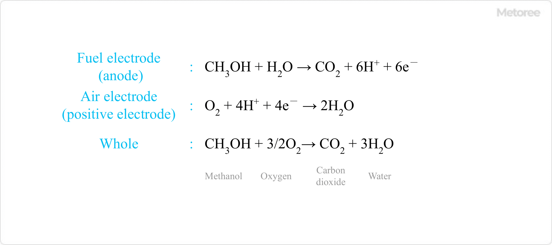
Figure 1. Reaction equation of a methanol fuel cell

Methanol fuel cells are fuel cells that use methanol directly as fuel, and are often referred to as methanol fuel cells. It consists of a fuel electrode (anode), where methanol reacts, and an air electrode (cathode), where oxygen from the air reacts. The reaction equation at each electrode is shown in Figure 1.

The reaction of methanol in aqueous methanol solution generates electrons through the action of a catalyst such as platinum in the fuel electrode, which continues to react as long as the fuel continues to be used. By generating electricity while supplying methanol, the fuel can be used for a long period.

2. Reforming Methanol Fuel Cell

Methanol-Fuel-Cells_メタノール燃料電池-2

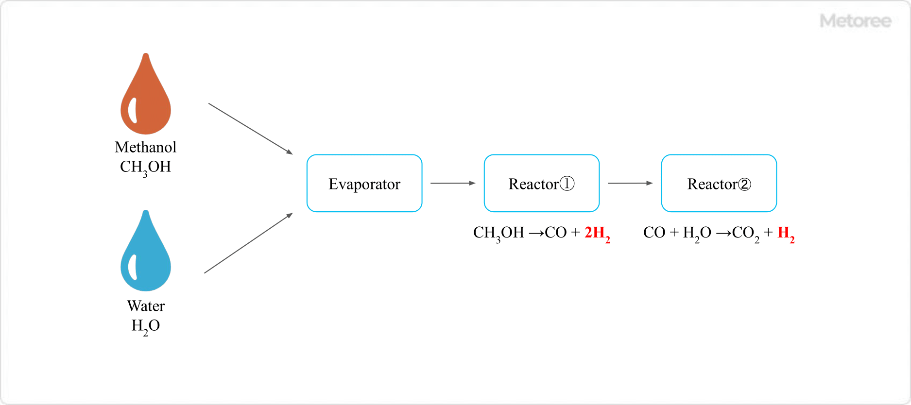
Figure 2. Modification of methanol

Reforming refers to extracting hydrogen from methanol. Since the extracted hydrogen is used as fuel to generate electricity, the principle of power generation is exactly the same as that of general hydrogen fuel cells, but since the starting material is methanol, these cells are also sometimes referred to as methanol fuel cells.

In methanol reforming, methanol is mixed with water vapor and reacts with a catalyst such as copper, zinc oxide, or aluminum oxide, which ultimately decomposes it into hydrogen and carbon dioxide.

Since this reaction is endothermic, heat must be supplied from an external source to advance the reaction. Although it is preferable to react at high temperatures to accelerate the progress of the reaction, the catalytic activity of the above catalysts is deactivated at temperatures above 300°C.

Other Information on Methanol Fuel Cells

1. Characteristics of Methanol Fuel Cells

Typical characteristics of methanol fuel cells include:

  • Small size
  • Small installation cost
  • Quiet operation
  • Low maintenance

While a typical fuel cell requires a hydrogen tank as well, methanol fuel cells can be made smaller because there is no need for a hydrogen tank. In addition, they do not rotate a turbine as in thermal or nuclear power generation, so they can generate electricity with quiet operation.

2. Challenges of Methanol Fuel Cells

Methanol-Fuel-Cells_メタノール燃料電池-3.

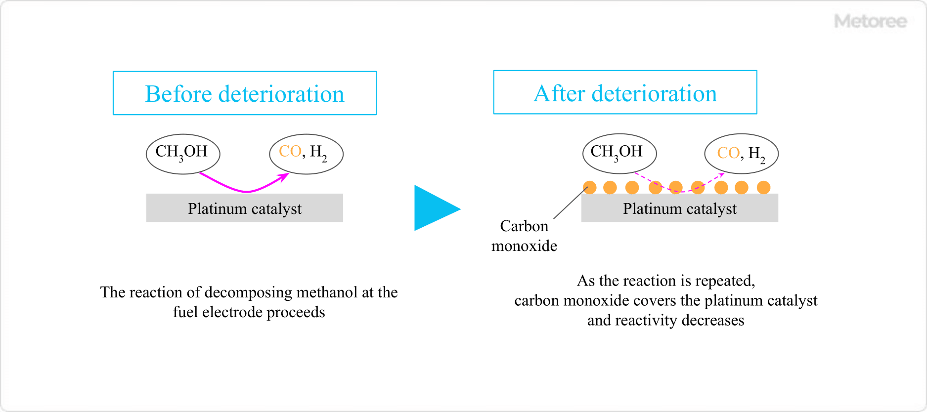
Figure 3. Decrease in reactivity of methanol fuel cell

In methanol fuel cells, the catalyst on the anode side that comes into contact with the methanol solution is contaminated by carbon monoxide, an intermediate product, resulting in reduced reactivity. This also shortens the life of the fuel cell itself.

Another major issue is the methanol crossover phenomenon, in which methanol permeates the electrolyte and reaches the air electrode, resulting in lower power generation efficiency and lower battery voltage. It can be said that fuel cells using methanol, which is inexpensive and easily stabilized but has a short product life, will take time to become widely used.

カテゴリー
category_usa

Air Flowmeter

What Is an Air Flowmeter?

Air Flowmeters

An air flowmeter is a flowmeter that measures the amount of air flowing through a pipe.

The principle of flowmeter measurement varies, and it can be used to measure a variety of gases and liquids. There are many flowmeter products, and the output method varies greatly depending on the product, such as those with only a sensor that measures flow rate and an electrical output, and those with a display unit.

Due to the difference in the principle of measurement, there are also many non-contact types that do not come into contact with the fluid to be measured.

Uses of Air Flowmeters

Air flow meters are widely used in manufacturing where fluids are used, such as chemical and petroleum plants, automotive, semiconductor, electronics, pharmaceutical, food, resin processing, and welding processes.

The fluids that can be used vary depending on the product. Many air flowmeters are capable of measuring not only air but also other gases, such as nitrogen and argon.

Flowmeters that are installed in a pipe may disrupt the flow. It is important to consider the extent of this effect before making a selection.

Principle of Air Flowmeters

An air flowmeter is a type of flowmeter that measures gas, and there are many principles of measurement. Examples of gas flow rates that can be measured are ultrasonic, differential pressure, thermal, and Kalman vortex.

1. Ultrasonic Flowmeter

This flowmeter utilizes the property of ultrasonic waves to propagate through a material. Ultrasonic waves are received diagonally across the gas in the pipe, and the difference in propagation time between the two ultrasonic waves is converted to a flow rate.

The advantages of ultrasonic flowmeters are that there is no pressure loss and that some types can be detected from outside the piping.

2. Differential Pressure Flowmeter

The principle of differential pressure flowmeters is based on Bernoulli’s theorem. An orifice is installed in the fluid flow path, and the flow rate is measured by detecting the pressure difference before and after the orifice.

The pressure difference is detected using a diaphragm. Advantages include low cost. Disadvantages include the need for a long, straight pipe section upstream and downstream of the flowmeter and a small maximum-minimum flow ratio.

3. Thermal Flowmeter

Thermal flowmeters measure the flow rate by detecting the amount of heat taken away from a heating element by a fluid. Since there are no moving parts, maintenance is not required, and even minute flow rates can be measured. There are also types that can measure temperatures ranging from several hundred degrees Celsius to ultra-low temperatures of -100 degrees Celsius or lower. Direct measurement of gas mass flow rate is possible.

4. Kalman Vortex Flowmeter

When fluid passes through an object, regular vortices are generated. Kalman vortex anemometers measure the flow rate by detecting the number of these vortices with a piezoelectric element or the like. It is susceptible to vibration and acoustic noise and requires a straight pipe section for installation.

5. Surface Flowmeter

In an area flowmeter, a float in a vertical tapered tube interrupts the flow from bottom to top, creating a pressure difference before and after the float. The meter rests at a position where the weight of the float and the force of the pressure difference are in equilibrium, and by reading the position, the flow rate can be measured.

The advantages of this type are its simple structure, low cost, and the fact that it does not require a straight pipe section or power supply. On the other hand, it also has disadvantages, such as large errors in the presence of pulsation and problems with dirt and wear of the float.

6. Coriolis Flowmeter

A Coriolis flowmeter consists of two U-tubes, a vibrating machine, and a force sensor. This flowmeter utilizes the principle of two oscillating U-tubes with fluid flowing through them, which generate forces in opposite directions to each other, i.e., Coriolis force.

Although the measuring principle has the disadvantage of increasing the overall length, it can directly measure the mass flow rate. It is highly accurate and responsive.

How to Select an Air Flowmeter

There are many types of flowmeters, and they are selected based on the object to be measured, the purpose of the measurement, and price.

1. Object of Measurement

The density, viscosity, conductivity, contaminants, corrosiveness, maximum and minimum flow rates, pulsation, temperature, pressure, and allowable pressure drop of the air to be measured are considered.

2. Purpose of Measurement

Once the intended use of the measured results is clarified, the measurement accuracy also becomes clear and the appropriate type of flowmeter can be selected. For example, if the purpose is to monitor or alarm the flow rate, high accuracy is not necessary.

Also, mass flow is often obtained by converting from volume flow, but if accuracy is required, a flowmeter that can directly measure mass flow is needed. Specifically, thermal or Coriolis flowmeters are suitable.

カテゴリー
category_usa

Vacuum Pressure Gauge

What Is a Vacuum Pressure Gauge?

Vacuum Pressure Combined Gauges

A vacuum pressure gauge is a pressure measuring instrument that measures negative pressure below atmospheric pressure.

There are three types of pressure gauges: pressure gauges, compound gauges, and vacuum gauges. Each of these instruments has a different range of pressure that can be measured: a manometer can measure only positive pressure, a compound gauge can measure a limited range of positive and negative pressure, and a vacuum pressure gauge can measure only negative pressure.

Therefore, care should be taken not to use vacuum gauges for measurements other than negative pressure, as this may cause malfunctions.

Uses of Vacuum Pressure Gauges

Vacuum pressure gauges are used in plasma etch spaces in semiconductor manufacturing equipment, metallurgy, organic synthesis, and other laboratory facilities. Other applications include ion beam equipment, vapor deposition equipment, and processing facilities requiring surface cleanliness.

For operations in which air is removed from piping to create a vacuum and then fill the piping with gas, vacuum pressure gauges are used to measure the degree of vacuum. A familiar example is when installing a new air conditioner.

By filling the inside of the air conditioner piping with cooling gas only, the air conditioner can be operated without malfunction.

Principle of Vacuum Pressure Gauges

There are three main methods for measuring vacuum pressure: mechanical phenomena, gas transport phenomena, and gas ionization phenomena.

1. Mechanical Phenomena

Measurements using mechanical phenomena can be made with U-tube manometers, McLeod vacuum gauges, diaphragm vacuum gauges, Bourdon tube vacuum gauges, and dead-weight vacuum gauges.

U-Tube Manometer
This differential pressure gauge is a glass U-tube, one end of which is sealed by exhausting it into a vacuum. It is capable of reading the pressure difference of gases from the height of the liquid column produced by the pressure difference, and is not affected by the type of gas. Therefore, it can measure absolute values of pressure.

McLeod Vacuum Gauge
This mercury liquid column pressure gauge is designed to measure high vacuum pressure. It is equipped with a mechanism that compresses gas to expand pressure and can measure absolute pressure.

Diaphragm Vacuum Gauges
This method reads the amount of deformation caused by pressure on the diaphragm mechanically, optically, or electrically.

2. Gas Transport Phenomena

A thermal conductivity vacuum pressure gauge is a vacuum pressure gauge that makes use of the gas transport phenomenon. It utilizes the property that the thermal conductivity of a gas varies with pressure.

There are many types of thermal conductivity vacuum gauges, including Pirani vacuum gauges, thermistor vacuum gauges, and thermocouple vacuum gauges. The important point to note about thermal conductivity vacuum gauges is that, at high vacuum, the effect of thermal radiation is greater than that of thermal conductivity. Therefore, thermal conduction vacuum gauges have the disadvantage that they cannot be used to measure high vacuum.

The Pirani vacuum gauge is a measuring instrument that detects changes in electrical resistance. It is based on a method in which an electric current is applied to a thin platinum resistance wire, and the change in platinum resistance due to heat lost by collision of gas molecules is detected by a bridge circuit.

3. Ionization Phenomena of Gases

This method uses the phenomenon of gas ionization to measure vacuum. There are several types of vacuum gauges, including hot cathode ionization vacuum gauges, cold cathode ionization vacuum gauges, and radiation vacuum gauges.

Hot Cathode Ionization Vacuum Gauge
The hot cathode emits thermal electrons to ionize the gas, and the ions produced are measured.

Cold Cathode Ionization Vacuum Gauge
This method ionizes gas by cold cathode discharge and measures ions.

Radiation Vacuum Gauge
Measures ions produced by radiation.

How to Select a Vacuum Pressure Gauge

Because there are numerous types of vacuum pressure gauges, the appropriate vacuum gauge must be selected for the intended purpose. The vacuum space for the purpose of measurement can be classified as low vacuum, medium vacuum, high vacuum, or ultrahigh vacuum.

  • Low vacuum (low vacuum) : 105Pa~102Pa
  • Medium vacuum (medium vacuum) : 102Pa~10-1Pa
  • High vacuum (high vacuum) : 10-1Pa~10-5Pa
  • Ultra-high vacuum (ultra high vacuum) : 10-5Pa~10-8Pa
  • Extremely high vacuum (extremely high vacuum) : 10-8Pa以下

U-tube mercury manometers and diaphragm vacuum gauges can measure in the low vacuum range. McLeod vacuum gauges can measure from high vacuum to low vacuum.

Pirani vacuum gauges are able to measure in the region of low to medium vacuum, and ionization vacuum gauges measure in the region of medium to ultra-high vacuum.

カテゴリー
category_usa

Resol Resin

What Is Resol Resin?

Resol resin is a type of phenolic resin.

It is obtained by reacting phenol and formaldehyde with an alkali catalyst and curing. There is also a type of resin called novolac. While resol resins use an alkali catalyst, novolac resins are reacted with an acid catalyst.

Also, while novolac is a thermoplastic resin, resol resins are thermosetting resins that cross-link and cure by heating.

Uses of Resol Resins

Today, resol resins are rarely molded as single items. They are generally processed into pellets and used as building materials. Examples include soundproofing and heat insulation materials, wall and ceiling panels, flooring materials, and architectural coatings. Resol resins are used because of their high heat resistance and fire resistance.

They are also compatible with a variety of base materials, so they are often used in combination with other base materials to take advantage of their respective properties. Generally, they are mixed with base materials to increase their strength before being molded. Phenolic resins, including resol resins, are used in large quantities in industrial products because of their high electrical insulation properties for their low cost.

When used as coatings for electronic components, they can reduce the risk of electric shock. As a molded product, it is sometimes used in switches and buttons of electrical appliances. In addition, it is sometimes used as a raw material for adhesives.

Adhesives containing resol resin are classified as phenolic resin-based adhesives and have superior water resistance and heat resistance compared to other resin-based adhesives. In this application, they are often used on their own.

Properties of Resol Resins

Resol resins have the following advantages:

  • High Strength and Hardness
    Resol resin is very hard, durable, and has excellent compressive, tensile, and shear strength.
  • High Heat Resistance
    Resol resin has excellent heat resistance and is suitable for use at high temperatures.
  • High Chemical Resistance
    Resol resin has excellent chemical resistance and is highly durable against chemicals, oil, and water.
  • High Flame Retardancy
    Resol resins are flame retardant, highly durable against fire, and have excellent fire resistance.
  • High Adhesive Strength
    Resol resins have high adhesive strength and are used as adhesives and paints.
  • Beautiful Tones.
    Resol resins have beautiful colors and can produce glossy surfaces.

On the other hand, phenolic resin is brittle due to its hardness, making it vulnerable to impact. In addition, although they are highly flame retardant and have excellent fire and flame shielding properties, the smoke and toxic gases generated by heating and combustion can be harmful to the human body.

Other Information on Resol Resins

1. History of Resol Resins

Phenolic resins, including resol resins, are the oldest synthetic plastics and have a long history. 1907 saw the invention of Bakelite in the US, which was initially used for decorative purposes such as watches due to its high gloss.

Later, as a substitute for metal, it became popular for tableware and kitchenware in the 1930s, and in the 1940s it was used for grips and hand guards for firearms, electrical plugs and switches, and automotive parts. However, the use of phenolic resin as it is decreasing due to the introduction of various plastic materials that are cheaper, suitable for mass production, and have a certain level of functionality.

2. Manufacturing Process of Resol Resin

The production of resol resin proceeds in a two-step reaction. The initial polymerization with an alkali catalyst is the first step and then the cross-linking through heating. First, phenol and formaldehyde are reacted in the presence of an alkali catalyst. At this point, the cross-linking has not yet progressed, and the resin is in a fusible state. It also has many hydroxymethyl groups and can be dissolved in solvents.

Next, an oxidizing agent such as sulfuric acid or chromic acid is added to the resol and heated. In this reaction, cross-linking proceeds, resulting in an insoluble, insoluble resin. Care must be taken to avoid too much cross-linking by heating at this stage. If cross-linking proceeds too far, the resin becomes brittle.

Taking advantage of this two-step reaction, it is possible to use general processing methods for processing thermoplastic resins, such as injection molding in the first step and then heating to cross-link, even though it is a thermosetting resin that hardens when heated and does not return to its original form. Note that the properties of resol resins vary depending on the amount and type of alkali catalyst and the reaction conditions between phenol and formaldehyde.

カテゴリー
category_usa

Soap Film Flowmeter

What Is a Soap Film Flowmeter?

Figure 1. Various flow meters

Figure 1. Various flow meters

A soap film flowmeter is a type of flowmeter that uses a soap film to measure the flow rate to be measured.

A flowmeter is a measuring instrument that measures flow rate, and there are various types of flowmeters. There are various types of flowmeters, such as ultrasonic flowmeters that use ultrasonic waves to measure the flow rate, differential pressure flowmeters that measure the pressure difference, and hot wire flowmeters that measure the flow rate by placing an electric heating wire inside the pipeline and measuring the amount of heat lost by the fluid in proportion to the flow rate.

Although the vesicle flowmeter measures a small amount of flow, it is a highly accurate and inexpensive flowmeter. Recently, electric annular flowmeters are available that automate all operations at the touch of a button and automatically calculate atmospheric pressure compensation and temperature compensation.

Uses of Soap Film Flowmeters

Soap film flowmeters are used to measure minute gas ventilation and leakage volumes, as well as to calibrate various types of flowmeters. The glass tube used for measurement can be made thinner to enable even more minute measurements.

The soap film flowmeter is characterized by its ability to measure gas flow rates accurately and to measure minute gas flow rates. There are many applications that take advantage of these features.

Another advantage of the soap film flowmeter is that it is small and simple in construction, yet it can visibly measure minute flow rates that you may not even notice are flowing. Flow is invisible, but you can visually confirm that it is indeed flowing.

Principle of Soap Film Flowmeters

Figure 2. Principle of soap film flowmeter

Figure 2. Principle of soap film flowmeter

The soap film flowmeter forms a soap film on the inside surface of a glass tube inside the instrument. By spraying the gas to be measured onto the soap film inside the glass capillary, the film is moved by the velocity of the gas. Since the glass capillary has a known volume, it is possible to calculate the flow rate of the gas to be measured, including the atmospheric pressure and temperature at that time, by measuring the travel time of the soap film with a detector.

However, the disadvantage is that the soap film flowmeter can measure only the length of the glass tube, so continuous measurement is not possible, and since a soap film is used for measurement, it is difficult to measure large flow rates that may cause the soap film to break. This is a disadvantage.

Figure 3. Corrections for atmospheric pressure and temperature

Figure 3. Corrections for atmospheric pressure and temperature

The necessary precautions when using a soap film flowmeter are that the use of a soap film may cause problems such as volume changes due to wetting of the gas from the point of use of the soap film, or permeation through the soap film of some gases. Particular attention should be paid to light gases, such as hydrogen gas. In addition, for precise measurement, atmospheric pressure correction and water vapor pressure correction must be performed.

More Soap Film Flowmeter Information

1. Maintenance of Soap Film Flowmeter

Soap film flowmeters require little maintenance compared to other flowmeters, but simple maintenance tasks do occur.

Soap Solution Refill
Since the liquid that creates the soap film gradually runs out, it is necessary to check the amount of liquid and replenish it. Replenishment fluid is sold by various manufacturers.

Glass Tube Cleaning
Glass tubes become gradually contaminated by airborne debris and require periodic cleaning.

  • Drain all soap solution.
  • Connect a vinyl tube longer than the glass capillary to the gas inlet.
  • Inject water through the vinyl tube to fill the glass capillary.
  • Leave for a while, then drain the water.
  • Refill with soap solution.

In addition, the air pump may need to be replaced every few years for manual types and the pulse motor for electric types.

2. How to Use Soap Film Flowmeter

The procedure may vary slightly from manufacturer to manufacturer, but is generally as follows:

  • First do the plumbing, wiring and setup.
  • Moisten with soap solution.
  • Set temperature, atmospheric pressure, etc., and calibrate.
  • Start measurement.

If the inside of the glass capillary is not moistened, the soap film will disappear even if it is created. Wetting can be done directly with soap solution in manual meters, or by repeated soap film generation in automated meters.

These flow meters are highly convenient because they can be used easily whenever you want to use them. Read each manufacturer’s instructions for detailed procedures.

カテゴリー
category_usa

DC Clamp Meter

What Is a DC Clamp Meter?

DC Clamp Meters

A DC clamp meter is a type of clamp meter that measures direct current (DC).

There are also alternating current (AC) clamp meters and dual-use (AC/DC) clamp meters. However, only a limited number of DC-only clamp meters are available, such as for microcurrent measurement. Normally, dual-use AC/DC clamp meters are used to measure DC current.

Clamp meters can measure the current value flowing through the wire of the circuit to be measured by clamping it between the wires. Normally, when measuring the current value, the circuit must be disconnected, and an ammeter inserted, but with a clamp meter, the wire is simply clamped between the heads, making it an easy and safe method.

Uses of DC Clamp Meters

As noted in the previous section, DC clamp meters are used for microcurrent measurement and can handle current measurements from 0.1 mA to 100 mA. On the other hand, general AC and DC clamp meters have a measurement range of 10 mA to 100 A or more, making DC clamp meters suitable for use in semiconductor electronic circuits.

Note that there are no DC clamp meters specifically designed for use in DC high-voltage circuits, and AC/DC clamp meters are used. Since clamp meters measure current without disconnecting the circuit, they are relatively safe to work with, even in high-voltage circuits. They are especially useful for electrical work, as they are extremely convenient.

Principle of DC Clamp Meters

Clamp meters, including DC clamp meters, consist of a clamp section that clamps the wire to be measured and a processing section that converts the strength of the magnetic field detected by the clamp section into a current value and displays it. Normally, when electricity is flowing through a wire, magnetic field lines are generated around the wire. These magnetic field lines are confined in the core of the clamping section.

The clamping section consists of two components: a core made of magnetic material and a means of detecting the magnetic field lines in the core. A part of the core can be split, through which an electric wire is clamped. The core is closed during measurement. The clamps for AC currents are widely used to detect the current flowing through the wire by using the principle of a transformer with a coil wound around the core, but these clamps cannot measure DC currents.

The clamping part that measures DC current is mainly made of a Hall element embedded inside the core. Hall elements use the Hall effect, which outputs a voltage corresponding to the density of magnetic field lines in the core, and thus can measure current even for DC. Hall elements also respond to alternating current, so the current value flowing through the cable can be calculated by measuring its output voltage.

Therefore, clamping parts using Hall elements are mostly compatible with both AC and DC currents, but they have the disadvantage that if the core is magnetized, the effect will cause a large measurement error in the current value. Therefore, it is necessary to remove the residual magnetism of the core periodically. The part of obtaining the current flowing in the wire from the output voltage of the Hall element is handled by the processing section.

Other Information on DC Clamp Meters

How to Use a DC Clamp Meter

1. Clamping Method
Operation of the clamp meter is extremely simple: just clamp the cable on the head. Placing the cable in the center of the head minimizes the measurement error, but even a slight misalignment will not have a significant effect.

2. Direction of Current
When measuring DC current, care must be taken to determine the direction of the current flowing through the cable. The head of a typical clamp meter is marked with a “+” and “-” symbol. This is a guide to indicate the direction of the current. When the DC current flows from “+” to “-“, it is a positive current value, and when it flows from “-” to “+”, it is a negative current value.

3. Leakage Current Measurement
When measuring the current flowing through a device, either the outward or return cable is passed through the head. However, if there is a leakage current inside the device, part of the current flows to ground (earth), resulting in a slightly lower return current than the outward current.

Therefore, measuring the current flowing across the ground wire with a clamp between them can be regarded as leakage current. Since the leakage current is only a few mA to several tens of mA, a clamp meter dedicated to DC measurement is also suitable for this application.

カテゴリー
category_usa

Semi-automatic Arc Welding Machine

What Is a Semi-Automatic Arc Welding Machine?

Semi Automatic Arc Welding Machines

A semi-automatic arc welding machine is a type of welding machine in which the metal used for welding is supplied automatically.

Normally, when welding metals, work is performed by heating the molten metal necessary for welding with a heating device called a torch to melt it. If this is done manually, both hands are occupied by the hand holding the molten metal and the hand holding the torch, making it difficult to fix the metal to be welded. Therefore, semi-automatic arc welding machines were created to perform only the work of melting the molten metal automatically.

Uses of Semi-Automatic Arc Welding Machines

Semi-automatic arc welding machines are generally used when you want to weld metal to metal. Because the molten metal is fed automatically, welding can be done much faster than with manual welding operations.

However, the disadvantage is that the finish is not as good as manual welding, so it is often used for welding parts that are difficult to see, such as welding truck beds or welding angles and pipes for assembling structures.

Principle of Semi-Automatic Arc Welding Machines

A semi-automatic arc welding machine consists of a torch, a tip device that can melt molten metal, a device that supplies molten metal, and a power source that controls these devices. A switch lever is attached to the torch, and by pressing the lever, an electric current flows, which transfers heat to the metal to be welded or the molten metal to be welded, allowing welding to take place.

The molten metal must not react with oxygen. For this reason, semi-automatic arc welding machines are generally designed to emit a jet of gas from the tip of the welding machine.

The type of semi-automatic arc welding machine also depends on the type of gas to be jetted.

These include CO2 welding, which uses carbon dioxide or other carbon dioxide gas as the shielding gas, MIG welding, which uses argon or helium, and MAG welding, which uses a mixture of 20% carbon dioxide gas and 80% argon gas.

However, because gas welders are susceptible to wind, they must be used indoors.

Types of Semi-automatic Arc Welding Machines

Semi-automatic arc welding machines are available in the following types:

1. CO2 Welding

The advantage of using carbon dioxide is that it is inexpensive, and it is also characterized by its deep penetration and high strength. The finished product is neither good nor bad, but the disadvantage is the high risk of burns due to the large amount of spatter (sparks) produced.

In addition, CO2 cannot be used for welding aluminum or stainless steel because it causes a chemical reaction with nonferrous metals.

2. MIG Welding

Since inert gas is used, spatter is less likely to occur, which has the advantage of achieving a very clean weld surface. In addition, nonferrous metals such as aluminum and stainless steel can only be welded with MIG.

The disadvantages include the high cost of inert gas and the tendency of inert gas to spread the arc, resulting in shallow penetration.

Therefore, the strength is inferior to that of other gas arc welding.

3. MAG Welding

This welding method uses a mixture of inert gas and CO2, which produces less spatter than CO2 and has the advantage of lower running costs compared to MIG.

It is also a method with superior strength due to its deeper melting depth. On the other hand, it has the disadvantage that it cannot be used for welding aluminum and stainless steel because it contains CO2.

Other Information About Semi-automatic Arc Welding Machines

Features of Semi-Automatic Arc Welding Machines

Because the molten wire is fed automatically, even technicians unfamiliar with welding have the advantage of being able to weld relatively easily. In shielded-arc welding, which is a typical manual welding method, the welding rod becomes shorter as it is welded, so it must be fed at a constant speed to the end of the welding point while maintaining the optimum distance from the base metal.

The advantage of semi-automatic arc welding machines is that they automatically maintain the distance from the base metal, so that optimal processing can be achieved by paying attention only to the feed rate.

カテゴリー
category_usa

Industrial Tablet

What Is an Industrial Tablet?

Industrial Tableting

Industrial tablets are tablet PCs that can be used for on-site work.

Tablets are lightweight and easy to carry, and have been widely used in general households. In recent years, there has been an increase in the number of applications in various industrial fields to improve work efficiency and productivity.

On the other hand, the specifications required for on-site work differ greatly from those of personal tablet PCs. For example, in addition to durability, such as waterproof, dustproof, and shock resistance, and high performance for comfortable operation, security robustness is required to prevent information leakage.

Uses of Industrial Tablets

Industrial tablets can be used for in-vehicle terminals that are subject to vibration and shock. Others are used outdoors, such as at construction sites where they are exposed to rain and wind. They can also be used indoors where water droplets and dust are a concern, such as machinery manufacturing sites and food processing plants.

Since different sites require different performance and functionality, industrial tablets are customized. For example, they can be fully waterproof for use in wet areas, or painted to match corporate colors.

Industrial tablets are available with a wide range of accessories. Specifically, cradles, shoulder straps, hand straps, etc. can be utilized depending on the application.

Structure of Industrial Tablets

Industrial tablets, like regular tablets, consist of the CPU, memory, and other parts that make up a PC, as well as a touch panel display.

Tablets use a common operating system (OS) such as Windows, with enterprise versions such as Windows 10 IoT Edition.

A new version of a typical OS is released every two to three years and must be updated for continued use. Compatibility with older versions means that some tablets can no longer be used with previously used software or devices. On the other hand, industrial tablets are updated in relatively short periods of time, such as two to three years, and incompatibility is not desirable for business purposes. For this reason, industrial tablets are often equipped with operating systems that do not require functional updates.

How to Select an Industrial Tablet

When selecting an industrial tablet, it is necessary to consider the environment of the site where it will be used.

For example, dust and waterproof performance are required for construction sites, factories, and outdoor sites, where dust and water may enter. Furthermore, not only are cold and shock resistance often required, but the communication environment is also important.

When used for inventory management or transportation management in warehouses, etc., it is necessary to check whether the inventory management system or picking system installed in the company can be installed in order to improve operational efficiency. In addition, when used outdoors, such as at construction sites, the screen must be able to be operated by touch without problems even if it rains, the screen gets wet, or the user is wearing gloves.

1. Dustproof and Waterproof

Dustproof and waterproof are important features for tablet use in the field. General tablet PCs are also waterproof, but the amount of dust and moisture generated in the field differs greatly, so a higher level of dustproof and waterproof functionality is required. For this reason, industrial tablets are covered with a thick case around the tablet and other measures are taken.

2. Security

Industrial tablets store important confidential information, such as company production, logistics, and development plans, so information security measures are essential. However, because tablets are easily portable, there is a risk of loss. To counter such risks, it is necessary to set access restrictions, thoroughly record when information is taken out of the office, install anti-virus software, and encrypt information.

3. Radio Wave Environment

Since the signal environment may be poor at outdoor sites, some industrial tablets have systems that allow users to create reports and refer to manuals, even in an offline environment.

If the system is designed to operate in an offline environment, the existing software also needs to store data locally instead of in the cloud so that it can operate in an offline environment.

4. Explosion-Proof Measures

In chemical plants and other workplaces where organic solvents are handled or where a lot of dust is generated, electronic equipment can become a source of ignition and cause serious accidents. Explosion-proof tablets that can be used in such workplaces are also available.

Like other industrial tablets, explosion-proof tablets have waterproof, dustproof, and security functions, and can be used onsite as industrial tablets.

カテゴリー
category_usa

Electromagnetic Wave Analysis

What Is Electromagnetic Wave Analysis?

Electromagnetic wave analysis is a type of numerical analysis method that uses a computer from the initial stage of product development.

It is a type of CAE (computer aided engineering) that visualizes electric and magnetic fields in the high-frequency range and is used to study countermeasures for EMC (electromagnetic compatibility).

It can be used for waveguide analysis in a two-dimensional domain, resonance analysis in a three-dimensional domain, and transient analysis.

Uses of Electromagnetic Analysis

The most common uses of electromagnetic wave analysis are numerical analysis using computers during product development and analysis of defects during development.

Electromagnetic wave analysis is a type of electromagnetic field analysis, and is also used in the analysis of circuits for radio communication, antennas, and radars that use high frequencies, as well as in electromagnetic compatibility analysis for EMC. Electromagnetic wave analysis has become a field of numerical analysis during product development and is an indispensable tool in the design and development of applied products using electromagnetics.

Types of Electromagnetic Wave Analysis

For example, the Method of Moments (MoM), which is useful for EMC analysis of unbounded radiation problems, is excellent for analyzing the structure of uniform dielectric materials. However, it is not suitable for the analysis of non-uniform structures.

The finite elements method (FEM) is a method that meshes the entire area of the structure for analysis and is good for modeling heterogeneous structures. However, it does not model radiation problems as effectively as the method of moments.

The finite difference time domain (FDTD) method meshes the entire space and, unlike the moment and finite element methods, performs the analysis in the time domain. This makes it suitable for transient analysis and excellent for modeling complex heterogeneous structures.

Principle of Electromagnetic Wave Analysis

In computer-based electromagnetic wave analysis, the medium is modeled by dividing space, generally called a grid, and Maxwell’s equations are solved for each grid. The discretization of the space used in the calculation consumes computer memory, and the more grids there are, the longer it takes to solve the equations.

For large-scale electromagnetic analysis, the amount of memory and CPU time used by the computer sets a limit on the calculations. Various boundary conditions, such as insulating boundary, periodic boundary, symmetry boundary, and impedance boundary, as well as time step and frequency, can be set according to the required analysis.

For electromagnetic analysis, it solves Maxwell’s equations in the full-time domain at each instant, the inverse matrix that summarizes the coefficients of the basic equation when modeled by the finite element method, the product of matrices in the transfer matrix method, and the integral equation at the moment method. When calculating with the split-step or beam propagation methods, the FFT and inverse FFT are solved.

How to Choose an Electromagnetic Wave Analysis

Electromagnetic wave analysis is a type of electromagnetic field analysis, and there are various methods used for noise analysis, etc. Each method has different characteristics. For example, it is necessary to fully consider which method to choose, whether the analysis is based on integral or differential equations.

And it is necessary to understand why high-frequency circuit approximations are used. Design feedback is important, taking into account the characteristics of the analysis method.

Structure of Electromagnetic Wave Analysis

The calculation results of electromagnetic wave analysis are presented along with numerical values in easy-to-read color-coded graphs and contour plots. Electromagnetism is a difficult phenomenon because it is invisible to the naked eye, and visual representations make it easier for people who are not familiar with electromagnetic fields and non-engineers to understand the phenomenon.

Electromagnetic field analysis software is also called an electromagnetic field simulator. The 2.5D simulators are classified into 2.5D and 3D based on the dimension of the structure that can be analyzed. 2.5D simulators can analyze a structure that consists of multiple layers, each layer having a 2D figure. However, structures with different electrical properties cannot be placed on the same layer.

カテゴリー
category_usa

Print Management

What Is Print Management?

Print management is the process by which each individual manages the printing of materials within a company or organization, including security enhancements, authorization settings, print job management, and printer settings.

Print management makes information visible and reduces the cost of printing materials. The main role of print management is to manage the printing costs collectively, limit the number of sheets to reduce printing costs, or force a change in settings to black and white.

It also limits unauthorized use of the printing press by requiring the scanning of IC cards or other devices to activate the press and by print management of the logs.

Uses of Print Management

Print management systems are installed in companies with several printing presses on a single floor or in schools with printing presses on the premises that can be used by anyone. The advantages of installing a print management system include the ability to manage the printing presses centrally at each location and to reduce wasteful printing costs.

Although many of today’s printers are capable of printing in both color and monochrome, the system can also control printing by limiting printing to monochrome.

Principle of Print Management

There are many principles of print management, but we will use the example of a company’s shared printing press to illustrate the principles.

The backbone of a print management system is a dedicated management server. This server centrally manages printing instructions obtained from employees’ PCs and sends signals to each printing machine. The employee then activates the printing machine through his or her IC card to start printing.

All of this printing information is stored on the server, so that if an error occurs, all information is sent to the Print Management PCs for prompt repair, and after repair, printing can be redone from immediately after the error occurred. In this way, the main function of print management is to manage all printing instructions obtained from multiple computers centrally and send printing instructions to the appropriate printer.

In addition, it is possible to send a signal to a printer to restrict the printing of a monochrome document that is scheduled to be printed in black and white from printing in color, which is a very costly process. Print management can also help to reduce costs significantly by eliminating waste.

How to Choose Print Management

When choosing a print management system, the following should be taken into consideration. It is also important to have a trial period and actually review the system before implementing it.

1. Functionality

Print management functions can be divided into those for users who print and those for administrators. At this point, it is important to make sure that the necessary functions are provided for each position.

2. Adequacy of Cost

It is necessary to confirm that the cost at the time of introduction and running costs are in line with the budget. It is important to estimate in advance how long it will take to recover the cost of printing, as print management can also help to reduce the cost of printing.

3. Operability

Printing functions may be used by any employee. Therefore, it is important to have an operation performance that allows the user to do what they want to do intuitively, not something that requires reading a manual beforehand.

4. Security

Most printed materials contain confidential information. Therefore, it is very important that the data stored on the server is not only leak proof, but also resistant to external attacks.

5. Support Adequacy

It is necessary to ensure that support and backup systems are in place in the event of a malfunction.