カテゴリー
category_usa

Laser Processing

What Is Laser Processing?

Laser processing is, as the name implies, processing using a laser.

A laser is a beam of light with the same phase and amplitude, i.e., coherent light. Laser processing uses a powerful, light-amplified laser beam to cut, weld, engrave, mark, or punch holes in the workpiece. The types of materials processed include metals, ceramics, plastics, wood, fabric, glass, and more.

Laser processing is a non-contact processing method that does not require the use of cutting tools, and it is capable of processing without deformation or distortion of the material due to stress or pressure. It also requires fewer consumables and is easier to maintain.

The main types of lasers used are carbon dioxide gas lasers, YAG lasers, fiber lasers, and excimer lasers.

Uses of Laser Processing

1. Carbon Dioxide Laser Processing

It is capable of high output power and is used for cutting sheet metal, microscopic drilling, and welding in industrial applications. In medical applications, it is also used for surgical laser scalpels.

2. YAG Laser Processing

Mainly used for spot welding of automotive engine parts, roofs and bodies.

3. Fiber Laser Processing

Used for cutting and welding metals, welding plastic materials together, and marking.

4. Excimer Laser Processing

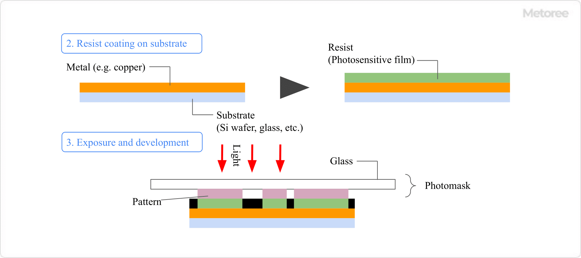
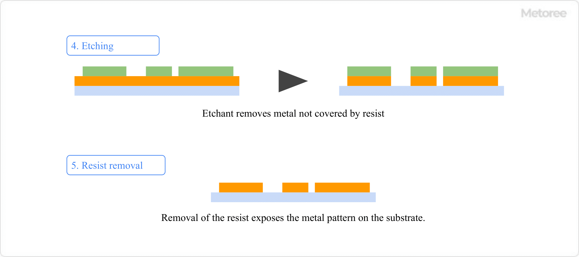
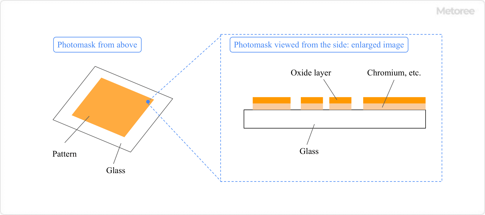
It is used as a light source for exposure in the semiconductor manufacturing process and in the low-temperature poly-silicon manufacturing process for liquid crystal displays.

Principle of Laser Processing

In general, when external energy (light, heat, etc.) is applied to atoms and molecules that make up a substance, the atoms move to a higher energy state (excited state). Then, they spontaneously emit light in an attempt to return to a lower energy state (ground state).

Especially when there are many high-energy atoms around, this spontaneous emission of light stimulates other high-energy atoms to emit light and return to the ground state. This light is called induced emission light, and its energy is amplified to twice that of the incident light.

When this induced emission light is repeatedly reflected by a mirror, it collides with electrons in other atoms, releasing light energy and producing an amplified, intense light. This is the principle of laser oscillation.

When processing a workpiece with this laser beam, a gas called a shielding gas is sprayed on the surface of the workpiece while protecting it from flying debris generated on the surface of the workpiece and preventing surface oxidation and ignition of the workpiece.

Types of Laser Processing

Laser processing is categorized by the substance that amplifies and oscillates the laser beam.

1. Carbon Dioxide Laser Processing

Uses laser light in the infrared region with a wavelength of 1.060 μm. It uses carbon dioxide-based gas as the laser medium.

2. YAG Laser Processing

It uses laser light in the infrared region with a wavelength of 1.064 μm. The laser medium is an artificial crystal composed of yttrium, aluminum, and garnet.

3. Fiber Laser Processing

The wavelength of the light is in the infrared region of 1.1 μm. This is a solid-state laser that uses an optical fiber as the laser medium. The laser light emitted from the excitation semiconductor is amplified by the optical fiber to produce a powerful laser beam for use in laser processing.

4. Excimer Laser Processing

The ultraviolet light source has a characteristic of very high optical energy. Laser beams with wavelengths in the deep ultraviolet region, such as 0.193 μm and 0.248 μm, are used. The laser medium is a mixture of inert gas (argon, krypton, xenon, etc.) and halogen gas (hydrogen chloride, fluorine).

Other Information on Laser Processing

Features of Laser Light

  • Directivity
    Laser light travels almost straight and true compared to natural light.
  • Monochromatic
    It is one color because the wavelengths of light are the same.
  • Coherence
    Since the phase and amplitude of light are the same, they can easily synthesize and strengthen each other.
カテゴリー
category_usa

Photoetching Process

What Is a Photoetching Process?

Photo Etching

A photoetching process is a processing technology that combines the principle of photography (photoengraving technology) and etching technology to remove unnecessary parts.

It can form complex and fine patterns on materials, such as substrates.

Uses for a Photoetching Process

The photoetching process has the following applications:

1. Electronic Board Fabrication

It is used to produce printed circuit boards that are built into most electronic devices. Printed circuit boards consist of copper foil attached to a base made of ceramics or resin. Unnecessary portions of the copper foil are removed by photoetching to produce electronic circuits.

Other uses include the production of flexible circuit boards (FPCs) and rigid circuit boards used in electrical products and cell phones. Components are used in circuit boards for touch sensors, temperature sensors, antennas, heaters, and camera sensors.

2. Fabrication of Electronic Circuits

It is used for fine patterning of semiconductors and liquid crystal displays.

3. Manufacture of Precision Parts

Used as a metal mask (stencil) to print solder paste on printed circuit boards in the surface mounting process where many electronic components are mounted.

Principle of Photoetching Processes

The photoetching process generally involves the following steps:

1. Mask Production

Draw mask patterns on glass and other materials.

2. Resist Coating on Substrate

A resist (photosensitive film) is applied to the substrate to be etched. Resist must be coated in a dark room, as it is altered by light.

3. Exposure and Development

Photo-Etching_フォトエッチング加工-1

Figure 1. Resist coating on substrate and exposure/developing

Expose with the mask created in step 1 placed on the resist coat. The area not covered by the mask is transformed and can be removed by the developer (only in the case of positive type. In the case of negative type, the unexposed areas will be removed by the developer).

4. Etching

The metal in the area where the resist was removed in step 3 is removed with an etchant. Etching on silicon substrates, for example, uses highly corrosive hydrofluoric acid as the etchant, so care must be taken when handling it.

5. Resist Removal and Cleaning

Photo-Etching_フォトエッチング加工-2

Figure 2. Etching and resist removal

The resist is removed and cleaned to complete the process.

Types of Photoetching Process

1. Metal Etching

After removing dirt from the material to be processed (stainless steel, copper, nickel, etc.), photoresist is applied to the reverse side of the material. After masking with a photomask, the photoresist is exposed to UV light to sensitize the photoresist.

Next, the photoresist is removed from the areas that were not illuminated by the photomask using specified chemicals. Finally, a metal-dissolving chemical (etchant) is used to dissolve the unmasked areas to obtain the pattern as designed.

2. Precision Hybrid Etching

This is a processing technique that combines etching and electroforming (a technique to create a model opposite to the master product). This processing technology makes it possible to manufacture precision products.

3. Etching of Special Materials

This method is used to etch very hard metals such as molybdenum and titanium.

4. 3D Etching

This is a method of etching three-dimensional or curved surfaces. Etching is performed on the inside of cylindrical products and on the outside of bar-shaped products.

5. Thin Film Etching

This is a method for etching thin metal films (ITO, Al, Cu, Ni, Cr, etc.) formed by vapor deposition or sputtering using a chemical process to form patterns with high processing accuracy.

Other Information on Photoetching Process

Photomask Fabrication Method

Photo-Etching_フォトエッチング加工-3

Figure 3. Photomask Structure

The photomask fabrication process is similar to that of photoetching. First, a pattern is drawn by CAD or other means. Next, a substrate with some kind of light-shielding film on a glass substrate is prepared.

There are three types of light shielding films: chrome mask, glass mask, and film mask, in order of processing accuracy. These substrates are called photomask blanks.

Next, resist is applied to the photomask blanks, and an electron beam or other means is used to draw the original mask that will become the basis of the product. Thereafter, in a process similar to photoetching, the light-shielding film is removed by a developer solution, and finally the resist is removed and washed.

カテゴリー
category_usa

Impact Test

What Is an Impact Test?

An impact test is a test to determine the degree to which a material can withstand an impact load applied to the material under test.

Usually, the test sample is fixed and then a pendulum hammer is swung down to the sample to apply the impact.

This impact test also reveals the strength of the material itself, which is useful for material selection in the case of a material base, and for quality assurance of the product in the case of a product state.

Uses of Impact Test

Impact tests can measure the impact resistance of the material itself or the product. Therefore, products that are prone to impact need to be evaluated by applying a shock that is appropriate for the environment in which they will be used.

Mobile products such as smartphones and tablets are most likely to be subjected to a drop impact during use, so impact tests are conducted under all conditions to ensure that they can withstand high impacts.

In addition, the products are also tested for impact during transportation to prevent damage caused by drop impact before they reach the consumer’s hands.

Principle of Impact Test

A drop test is similar to the impact test, but the drop test confirms the impact of a product dropped freely. The impact test is a hammer blow to a single point, which is a different type of impact test. Also, in an impact test, a high-speed load is applied to the test sample as it is struck at or above the velocity that occurs during a free fall.

Such impact tests can be performed by swinging a hammer on a pendulum down on a normally stationary test sample. The specific machines used for impact testing are the Izod impact testing machine and the Charpy impact testing machine.

1. Izod Impact Test Machine

In the Izod impact tester, one side of the test piece is fixed and is struck with a hammer from the unfixed side to measure the impact value.

2. Charpy Impact Test Machine

In the Charpy impact test machine, the left and right sides of the specimen are fixed, and the specimen is struck from the rear side with a hammer to fracture it and measure the impact value.

How to Choose an Impact Test

1. Izod Impact Test

The Izod impact test is used to check toughness, much like a golf tee shot. A small incision is made in the specimen and struck from a notched direction. The angle at which the hammer is lifted and the angle at which it is lifted can be measured. Measurements may be compared with notched and unnotched results.

In the Izod impact test, the movement of the hammer after breaking the specimen is important. If the specimen does not absorb the impact test, the hammer will swing up high; if the specimen absorbs the impact test, the hammer will swing down low. The test can be performed on a variety of materials, such as plastics and metals. Plastics have different impact strength at different temperatures, so it may be done at low and high temperatures.

2. Charpy Impact Test

Charpy impact tests can test for brittleness and strength based on the energy used during fracture. A specimen is placed in the testing machine and struck to the center with a pendulum, or, in the notched case, with a pendulum against the opposite side of the notch.

After swinging down, the hammer will swing up to the opposite side. The toughness can be checked by comparing the angle of swing up with and without the specimen. If the specimen does not absorb the impact test, the hammer swings up to a high place, and if the specimen absorbs the impact test, the hammer does not swing up so much. The test is performed on all kinds of products, such as plastic, wood, and metal.

Types of Impact Tests

1. Falling Ball Impact Test

In a falling ball impact test, a steel ball is dropped from a specified height onto a product or material to determine its toughness.

2. DuPont Drop Impact Test

The DuPont drop impact test is a test to determine the strength of plastic sheets and coatings. Since plastics and coatings can peel or crack due to impact, a simulated impact is applied to determine the fragility of the product.

3. Dirt Impact Test

Dirt impact test is a test to determine if a specimen is destroyed when a dart is dropped onto a plastic board, glass, or building board.

カテゴリー
category_usa

Corrosion Testing

What Is Corrosion Testing?

Corrosion testing is a general term for testing to confirm corrosion resistance under conditions that accelerate corrosion by extracting environmental factors that corrode materials.

Corrosion is one of the factors that cause products to break. Corrosion is caused by a complex combination of various environmental factors, and it is difficult to reproduce it completely. Even if it could be reproduced in a pseudo-realistic manner, it would require extensive testing. However, elemental testing can be performed simply by extracting the environmental factors that are thought to affect corrosion.

Since corrosion testing is conducted under conditions that dare to accelerate corrosion, it is possible to evaluate corrosion resistance in a relatively short period, and it is easy to compare the results with other materials.

Uses of Corrosion Testing

Corrosion testing is used as a standard for selecting materials and evaluating the corrosion resistance of products. For example, only materials that exceed a certain standard are used as materials.

There are also standardized corrosion evaluation standards which are used in a wide range of fields, including the automotive, home appliance, electrical appliance, civil engineering, and construction fields.

Principle of Corrosion Testing

Corrosion testing is performed using the mechanism of degradation caused by chemical reactions of materials. Degradation due to physical actions such as abrasion or scratches is not called corrosion, but only degradation due to chemical reactions.

First, in corrosion testing, the materials used in a product are placed in the environmental factors of the environment in which the product is likely to be used. For example, if the product is to be used in a coastal area, the environmental factors are the components of seawater, and if the product is to be used outdoors, the environmental factors are the components of acid rain.

The product is then left for a certain period under conditions that accelerate corrosion and observed. Over time, we will clarify the manner of corrosion and the time it took to corrode.

Types of Corrosion Testing

There are various types of corrosion testing, depending on the combination of materials and environmental factors. Among them, there are four typical tests that are commonly performed:

1. Real-World Exposure Tests

This corrosion testing is not an accelerated test, but rather a test to see how the material corrodes over time under actual environmental conditions. Also called weathering resistance testing, this test examines how corrosion progresses under the influence of light, humidity, water, and other factors.

It is often used to check the corrosion of bridges, buildings, machinery, vehicles, etc., which are mainly left outdoors for long periods of time. It can confirm the correct degree of corrosion, but it is not an accelerated test, and the test period is long.

2. Simulated Environmental Exposure Test

In this corrosion testing, the most corrosion-promoting conditions are selected according to the material to be tested, and the degree of corrosion is checked under the conditions that are most likely to promote corrosion.

Since the test is conducted under more severe conditions than corrosion that occurs in a real environment, it is possible to determine the limit value of the corrosion resistance strength of the material and to examine its corrosion resistance in a short period.

3. Electrochemical Corrosion Testing

In this corrosion testing, a pseudo-corrosive environment is created by adding electrochemical reactions, and the conditions under which corrosion occurs and its degree can be measured.

Specifically, corrosion resistance is evaluated using electrochemical measurement tests such as corrosion potential measurement, anodic polarization curve measurement, and impedance measurement testing. Evaluation combined with high-temperature, high-pressure water corrosion testing is also available.

4. Localized Corrosion Testing

In this corrosion testing, a material is immersed in a solution that is prone to corrosion, and stress is applied to cause strong corrosion in one area.

This test is used to evaluate metallic materials whose oxide film is destroyed by heat or force and corrodes at once.

Other Information on Corrosion Testing

Major Corrosion Factors Used in Corrosion Testing

Corrosion testing involves the use of various corrosion factors that can corrode materials. Commonly used corrosion factors are:

1. Salt Water
This factor is used for corrosion testing of materials left or used in coastal areas such as the sea. Tests using salt water include the salt spray test.

2. Acid Rain
This factor is used for corrosion testing of materials that are left or used near factories or in the open air. It is used, for example, in combined cyclic testing (CCT), which assumes atmospheric corrosion testing.

3. Gas and Ozone
This factor is used to examine the corrosion of materials used in factories and other places where corrosive gases are generated. Corrosive gases such as sulfur dioxide, hydrogen sulfide, nitrogen dioxide, chlorine, and ozone are used in gas corrosion testing.

4. Light
This factor is used for corrosion testing of materials that are left or used in places where they are exposed to sunlight. It is used for weathering resistance testing.

5. Low Temperature
This factor is used in corrosion testing of materials used in cold climates. It is used in temperature and humidity constant temperature and humidity cycling tests to examine coating hardening, embrittlement, and delamination due to low temperatures.

6. Wetting
This factor is used for corrosion testing of materials used in humid environments. It is used in water vapor oxidation tests, constant temperature and humidity, and temperature and humidity cycling tests.

7. Drying
A factor used in corrosion testing of materials used in low-humidity, dry areas. It is used in drying tests.

8. Chipping
This factor is used in corrosion testing that assumes corrosion that progresses from collisions and abrasions from road pebbles and other objects that are rolled up by driving automobiles and other vehicles. It is used in weathering tests.

カテゴリー
category_usa

Fatigue Testing

What Is Fatigue Testing?

Fatigue Testing Services

Fatigue testing is a test in which a load is repeatedly applied to a test sample to determine at what point this test sample is destroyed.

Even if a metal is subjected to a small load that does not break in one time, an invisible crack is generated by repeated application of the load. This is called “cracking.”

If further load is applied while cracks have formed, the metal will eventually fracture. This is called “fatigue failure.” Fatigue testing is used to investigate the number of times until fatigue failure occurs.

Uses of Fatigue Testing

Fatigue testing is performed on almost all products in which metal is used. It is no exaggeration to say that fatigue testing is indispensable, especially for products that are expected to be used repeatedly, such as automobiles, cables, and overpasses.

Fatigue testing is also used to determine durability against bending operations. This is because metallic materials are often processed in long and narrow shapes and are prone to small cracks as a result of repeated bending.

In addition, although not to the same extent as metals, rubber and resins also have a lower rupture stress when subjected to repeated loading. Depending on the material and application, fatigue testing is recommended, as with metals.

Principle of Fatigue Testing

Fatigue testing is performed in the following sequence:

  • A sample is cut from the metal material used for the product to be tested.
  • The specimen is placed in a special machine and subjected to a load.
  • A graph is created by plotting the load and the number of times a rupture occurs.
  • The fatigue limit point is calculated from the curve obtained by the graph.

The S-N diagram can be created by plotting the “magnitude of the load (stress)” on the vertical axis and the “number of times the load has ruptured” on the horizontal axis.

The S-N diagram shows that the load is horizontal after a certain stress. This stress is called the fatigue limit, which is the force at which fatigue failure does not occur, no matter how many times the load is repeated. By multiplying this fatigue limit by the safety factor, the allowable stress of the material can be calculated.

In order to create an accurate S-N diagram, it is important to test with a well-balanced set of large and small loads. It is recommended that at least six different loads be given and that as many points as possible be shaken to perform the test.

Types of Fatigue Testing

There are many types of fatigue testing. The type of test to be evaluated and the magnitude of the load will depend on the product and operating environment in which the test sample will be used.

  • Rotating Bending Fatigue Testing
    Tests to evaluate whether a rotating shaft can withstand its own weight, etc.
  • Tensile-Compressive Fatigue Testing
    Testing of materials in tension or compression
  • Giga-Cycle Fatigue Testing
    Test to fracture by applying low stress 10 times
  • Plane Bending Fatigue Testing
    Tests to evaluate the durability of steel sheets under bending loads.
  • Thermal Fatigue Testing
    Repeated heating and cooling tests with fixed displacement
  • Torsional Fatigue Testing
    Tests in which torque is repeatedly applied to a specimen
  • Ultrasonic Fatigue Testing
    Tests in which specimens are vibrated by ultrasonic waves
  • Internal Pressure Fatigue Testing
    A test to evaluate the durability of a pressure medium by increasing the pressure in the specimen.
  • Fatigue Crack Propagation Testing
    Fatigue testing to evaluate fatigue crack growth rate

Torsional fatigue testing is essential for automobile shafts because they are subjected to repeated torsional loading. In addition, there are two types of tension-compression fatigue testing: high-cycle fatigue testing, in which the entire surface of the specimen is subjected to loading, and low-cycle fatigue testing, in which loading is applied only to areas where stress is concentrated, such as steps.

For products that may be subjected to localized stress, it is recommended that both tests be performed.

Other Information on Fatigue Testing

Background on Fatigue Testing

The background of fatigue testing is that “metals are not always destroyed only when they are subjected to strong loads.” Machines and structures are often broken by “repetitive loading” in which force is applied periodically, which is said to be about 80% of the time.

If fatigue testing is not used to make the correct assessment, serious accidents may result. For example, the 2007 “ExpoLand roller coaster rollover accident” is said to have been caused by destruction due to axle fatigue.

To prevent such a situation, it is important to conduct fatigue testing appropriate for the material and uses of the product, and to calculate the upper limit of stress (allowable stress) that can be used for the material.

カテゴリー
category_usa

Bending Test

What Is a Bending Test?

Bending test is a tester to check the durability of products, such as robot cables and optical fiber cables that are likely to deteriorate as the number of bending cycles increases, by daring to bend them repeatedly.

For long, thin products, such as cables and wires, the weight of the cable itself may cause the wire to bend, and bending may be applied during the wiring process. If the durability against bending is weak, there is a risk of wire breakage, so a bending test is necessary.

There are two types of bending tests: a three-point test with two fulcrums and one action point, and a four-point test with two fulcrums and two action points. The three-point test is mainly used because the process of cable bending in wiring is the same situation as in the three-point test.

However, in examining the durability of a cable, it is important to choose the test method that best suits the purpose, since the 3-point test and the 4-point test are sometimes used interchangeably.

Uses of Bending Test

Bending test is used to examine the durability of cables by bending power supply cables and wiring devices. The purpose of bending test is to check the durability of cables when they are bent in various directions and to determine whether the cables have the desired durability.

Cables bend in different directions depending on the product. Therefore, test methods differ depending on the bending direction and torsion, and the test content is customized for each product. For example, a 3-point or 4-point test is used for bending test. A torsion test may also be used to examine the durability of external force due to torsion.

Usually used for electric wires and cables, but also often used to check for cracks and tears in rubber products that stretch and shrink rapidly, thin optical films, and so on.

Principle of Bending Test

Bending test consists of forcing a cable-like object to bend using a jig. Usually, the cable is bent by placing it between jigs called mandrels with radii. The test with the jig is the same as the principle of the 3-point test for bending tests.

By using jigs with different R values, it is possible to set the desired angle of bending. The objective is to check the durability by repeating the bending operation. In the bending test, the test sample is bent along the curved surface of the R of the jig, so the selection of the jig is also important for evaluating the correct durability.

The twist test and U-bend test are used in conjunction with the bending test to evaluate the durability of cable-like materials. As in the bending test, the durability of the cable is checked by forcibly twisting and folding the test sample. The items required for these tests vary depending on the uses of the test sample and the processing process.

Other Information About Bending Test

Other Test Methods

Bending test requires a twist test or a U-fold test in addition to the bending test. There are also testing machines that use the same principle as the 3-point test for bending tests.

The phenomena to be evaluated vary with each testing method. For example, the torsion test evaluates torsion phenomena, while the U-fold test evaluates bending phenomena.

1. Twisting Test
The twist test is a test to examine the durability of a cable when it is twisted. The cable is set in the durability tester and supported at both ends by a jig, then bending is applied to the cable.

2. U-Fold Test
The U-bend test is a test in which a jig is attached to the top of a bent cable and an external force is applied. Some testing machines can test many cables at once by arranging them in parallel.

3. 3-Point Test
The three-point test is a test in which an external force is applied to the center of the specimen, supporting both ends of the material. It is called a 3-point test because the external force is applied to three points: two at both ends and one at the center.

The purpose of the three-point test is to determine whether a material is suitable for bending since the external force is applied similarly to the bending process of the material. The bending test, which is used to examine the durability of a cable, consists of supporting both ends of the testing machine with a jig and applying an external force to the center.

カテゴリー
category_usa

Ultrasonic Metal Joining Machine

What Is an Ultrasonic Metal Joining Machine?

Ultrasonic Metal Welders

Ultrasonic metal joining machines are machines that use air vibrations generated by ultrasonic waves to join metals together.

Normally, heat is used to melt metals when joining metals, but ultrasonic metal joining machines do not use heat. Ultrasonic joining machines, however, do not use heat. Ultrasonic waves cause metal atoms to vibrate, making it possible to join metals with different melting points.

On the other hand, the disadvantage is that the joining strength is weak because the metal is not melted once and then joined completely, as is the case with heat. Therefore, care must be taken when seeking high strength.

Metal joining can be broadly classified into three categories. Specifically, there are three types of metal joining: fusion welding, in which the joint is heated and melted; solid phase welding, in which mechanical pressure is applied to cause plastic deformation of the joint; and brazing, in which a solder material with a low melting point is applied to the joint. Ultrasonic bonding is classified as solid phase bonding.

Uses of Ultrasonic Metal Joining Machines

Ultrasonic metal joining machines are used to join items that should not be affected by their surroundings, such as foil lamination of battery electrodes and joining copper wires to connector terminals. Ultrasonic Metal Joining Machines do not melt metal with heat, so the material itself is not subjected to intense heat.

Therefore, there is little effect of heat on other parts of the joint. However, since the connection strength is not high, it is not suitable for large moving parts.

Principle of Ultrasonic Metal Joining Machine

When metals are exposed to air, an oxide film is formed on the surface or foreign matter adheres to the surface. When these materials are adhered, joining is not possible unless the bonding surface is melted once.

However, when ultrasonic vibrations are applied parallel to the bonding surface while pressure is applied vertically to the metal, the ultrasonic vibrations cause the metals to rub against each other, peeling off the oxide film and adhesions to expose the metal surface. The interatomic force enables atoms to bond to each other without melting the metal.

Once the metal is melted, if the metal surface is thin, the shape itself may be deformed or shrink. However, with ultrasonic metal joining, the force acts on only a small layer of the joining surface, so the shape is not greatly disrupted.

Also, since only ultrasonic energy is used, no gas is consumed. The consumption of electrical energy is also greatly reduced, making it an environmentally friendly joining method.

Structure of Ultrasonic Metal Joining Machine

Ultrasonic metal joining machines consist of an oscillator, a vibration unit, and an ultrasonic horn.

1. Oscillator

It provides high-frequency power and controls the frequency. Since the frequency varies with each ultrasonic horn used and fluctuates depending on the temperature and pressure conditions during operation and operation, a frequency tracking circuit is included to adjust the frequency to the optimum level.

2. Vibrating Section

The vibration section consists of a transducer and a fixed horn. The frequency sent from the oscillator is transmitted through the transducer to the fixed horn, which amplifies the amplitude.

3. Ultrasonic Horn

In the ultrasonic horn, the ultrasonic vibration from the vibrating section and the applied pressure cause instantaneous frictional heat on the workpiece joining surface, which melts the contact surface of the workpiece and bonds the molecules to each other. When the ultrasonic vibration stops, the molten workpiece rapidly cools and solidifies.

If pressure is applied continuously during cooling, the bonded surfaces will solidify in a denser state, resulting in a stronger bond.

Ultrasonic Metal Joining Machine Features

Ultrasonic metal joining machines are safer, quicker, and more accurate than other joining methods. Joining by ultrasonic waves is a spot joining process, which allows for precise processing. In addition, it takes only a few seconds to join.

Except for the spot portion, there is little effect on the metal, and damage or deformation is unlikely to occur. Due to solid phase bonding by ultrasonic waves, the temperature rise to the base metal is slow, and bonding is possible at a relatively low temperature of 35% to 50% of the base metal’s melting temperature.

Therefore, there are no sparks or smoke, and excellent strength and conductivity can be ensured.

カテゴリー
category_usa

Floor Jack

What Is a Floor Jack?

Floor Jacks

A floor jack is a device that can lift heavy objects vertically with little force by using hydraulic or other power.

Floor jacks are mainly used to lift vehicle bodies, such as for car maintenance. There are several types of jacks used for car maintenance, and the two main types are pantograph jacks and floor jacks.

Pantograph jacks are screw-type and can lift heavy objects by manually turning a screw. They can also be folded, leading to space savings. While relatively easy to handle, they require a bit of force to raise and lower the jack.

Floor jacks use hydraulic pressure to lift heavy objects, making it easier to raise and lower with the jack and requiring less force.

Uses of Floor Jacks

Floor jacks are primarily used to raise and lower vehicle bodies in order to perform vehicle maintenance. Work performed by lifting the vehicle body includes changing tires and various oil changes.

Since cars are heavy objects, when using a jack to lift a car body, sufficient safety precautions must be taken. Also, since the position where the jack can be used (jack-up point) differs depending on the car model, it is important to check the maintenance manual that comes with the car thoroughly before using the jack.

A manual pantograph jack is pre-installed in the car as an on-board repair tool. A manual pantograph jack has a simple structure in which the pantograph moves up and down in accordance with the rotation of a screw, and its advantage is that it is small and takes up little space.

However, due to the small size of the jack itself, it takes a considerable amount of time to raise and lower the car body before it can be worked on, as it requires a lot of screw turning. Floor jacks are used for tasks such as changing tires so that the work can be completed quickly.

Principle of Floor Jacks

In principle, pantograph jacks are screw-type jacks, while floor jacks are primarily hydraulic.

1. Pantograph Jack

Pantograph jacks have a structure in which the pantograph moves up and down in accordance with the rotation of a screw. Since force is generated by the engagement of the screws, they are highly reliable and inexpensive due to their simple structure.

2. Floor Jack

Floor jacks are hydraulically operated and have an oil-filled tank inside. By raising and lowering the jack lever, pressure is applied to the oil in the tank, causing the oil to move toward the pump. As the oil moves toward the pump, the “ram” placed under the object to be lifted rises, allowing the heavy object to be lifted indirectly.

This action is based on Pascal’s principle of “when pressure is applied to a fluid” in a closed container, that pressure is transmitted equally to all parts of the fluid. Because hydraulic pressure can convert small amounts of energy into large amounts of energy, it is used in many situations in addition to jacks.

Hydraulic pressure is resistant to temperature changes in the surrounding environment, and it is easy to obtain high pressure, but its disadvantage is that if an oil leak occurs, the pressure is released. Therefore, if the container loses its airtightness due to age-related deterioration, etc., pressure can suddenly be released, which is dangerous, so hydraulic products should be inspected in advance for oil leaks before being used.

Compared to pantograph jacks, the equipment is a little larger because it uses the force of moving oil. The jack itself is also heavy, making it inconvenient to carry.

Types of Floor Jacks

1. General Floor Jack

Also known as garage jacks, these are general jacks that are raised and lowered mainly by hydraulic pressure. Depending on the product, they are mainly capable of lifting 1.5 to 2 tons.

In addition to hydraulic jacks, air jacks also exist, which use air power instead of oil to lift heavy objects. While these jacks can lift heavier objects more safely than floor jacks, they are the most bulky and can be used in a limited number of locations.

2. Low Floor Jack

This is a floor jack that can be lifted from a lower position. Depending on the shape of the vehicle and the height of the vehicle, it may be necessary to use this type.

The hydraulic system by which the jack is raised and lowered remains the same, but the height when lifted to the maximum is lower, so it is important to use this type of jack according to the uses of the vehicle.

Other Information on Floor Jacks

Pantograph Jack

Also known as a scissor jack, this jack has the same shape as the pantograph on the ceiling of a train. It takes time to raise the jack to the maximum because it is structured to move up and down by interlocking screws.

The greatest feature of pantograph jacks is that they are space-saving and inexpensive. Some products use hydraulic pressure instead of screws and can be easily raised and lowered.

カテゴリー
category_usa

Plastic Syringe

What Is a Plastic Syringe?

Plastic Syringes

A plastic syringe is a syringe that is manufactured entirely of plastic .

For disposable syringes that are not all plastic, see Disposable Syringes. A regular syringe has a syringe-like structure in which the gasket on the side of the cylinder (plunger) into which the liquid or gas is pushed is made of rubber.

Plastic syringes, however, are made entirely of plastic, and the rubber material does not leach out, so contamination from the rubber gasket does not occur in the syringe.

Uses of Plastic Syringes

They are mainly used as syringes for measuring specific volumes in medical or scientific experiments where leaching of components from rubber is a concern, or in scientific experiments where rubber can be used under conditions that would alter its properties but plastic can be used.

Plastic syringes have a graduated scale on the outer casing (barrel) to facilitate measuring and transferring the volume of liquid. Plastic syringes are relatively inexpensive and can be disposed of.

Principle of Plastic Syringes

Plastic syringes are designed to be airtight even when only plastic is used. In most cases, the barrel is made of hard polypropylene (PP) and the plunger is made of slightly softer polyethylene (PE), and this combination makes the syringe airtight.

If the gasket is a hard plastic that lacks elasticity, the barrel may be slightly deformed so that it adheres to the gasket to maintain airtightness.

Structure of Plastic Syringe

A plastic syringe is a syringe that consists of an outer tube (barrel), a pump handle (plunger), and a sealing component (gasket) that is attached to the plunger.

How to Choose a Plastic Syringe

1. Material

Make sure the material is suitable for your purpose. Most all-plastic syringes have a polypropylene (PP) barrel and polyethylene (PE) plunger.

2. Maximum Capacity and Scale

Since the size and scale differ according to the maximum volume, selection is made in consideration of the volume and scale increments to be used. While syringes used for medical equipment have a uniform scale for each size, the scale for syringes used for scientific experiments differs depending on the product series.

3. Tip Position (Middle or Side Mouth)

There are two types of plastic syringe tips: those with the outlet in the middle of the syringe tip (middle tip) and those with the outlet on the end (side tip).

Most medium- and small-capacity cylinders have a medium mouth, but most large-capacity cylinders have a side mouth. The advantage of the side mouth is that it is easy to vent even with thick syringes. In the case of medium-volume syringes, there may be products with both medium and horizontal mouths, and in this case, the one that is easier to use in actual operation should be selected.

4. Tip Shape

Since plastic syringes usually do not have a needle or other device attached to the tip, a syringe needle is often used at the tip to reach the liquid surface when the liquid is sucked up. Depending on the situation, a tube may be attached.

Most plastic syringes are luer-slip (luer-tip) or luer-lock syringes. The luer-slip (luer-tip) syringe is designed to hold a needle or other object in place by inserting it straight into the syringe.

The luer-lock type has a stopper that prevents the needle from coming out by rotating and twisting it after inserting it into the tip of the outlet. If there is nothing in particular to attach, a simple luer-slip type is used.

Other Information About Plastic Syringes

Advantages of All-Plastic

The greatest advantage is that since no rubber is used, the risk of rubber-derived contamination is low and the product can be used in solvent conditions that rubber cannot tolerate. The all-plastic design also makes it possible to manufacture the plunger and gasket as a single unit. It also reduces the risk of accidents where the gasket falls off during operation.

カテゴリー
category_usa

Fpd Manufacturing Equipment

What Is FPD Manufacturing Equipment?

FPD manufacturing equipment is a generic term for all equipment used to manufacture flat panel displays (FPD).

FPDs are flat, thin display devices that replace the cathode-ray tubes previously used to project images.

To manufacture these FPDs, 20 to 30 different processes are required, from designing the circuitry to testing whether the image is projected before shipment.

FPD manufacturing equipment, however, requires technology that can consistently process glass substrates at high speed and with high accuracy.

Uses of FPD Manufacturing Equipment

This FPD manufacturing equipment is placed in places where products using thin video display devices are manufactured.
When we hear about alternatives to CRTs, we tend to think of TVs, but they are used in many products other than TVs.

Examples include notebook computers, smartphones, and tablet devices.

It can be said that these products have become familiar in our daily lives because it has become possible to manufacture FPDs that are thin, light, and have high resolution.

Principle of FPD Manufacturing Equipment

There are 20-30 processes involved in the manufacturing of FPDs, but there are two major processes.

The first is the array process, which involves creating the array circuit by preparing the substrate and circuits necessary for the FPD.

This process requires a high degree of precision, as even the slightest deviation from the required array circuits will prevent them from working if there are problems with the circuits, impurities on the substrate, or if the photomasks are not firmly assembled.

Another process is the color filter cell module process, in which polarizing plates and other components are attached to the array circuit to complete the FPD.

All of these processes are performed by machine, and the equipment required is completely different.

Therefore, the technology required for each process differs greatly, and the process is quite complex.

Although the development of FPDs will not be possible without the development of technology in each process, the development of technology will enable the production of products that are more easily accepted by consumers, such as large-screen, thinner products that can be offered at lower prices.