What Is a Worm Gear Speed Reducer?
A worm gear speed reducer is a device that utilizes a worm gear as its reduction mechanism.
A speed reducer is a device that takes the rotational output of an electric motor or another rotary power-generating device as its input and reduces its rotational speed while increasing its torque. The reduction mechanism comprises various types of gears. One of these gear types is the worm gear, which is a combination of a worm (worm shaft) and a worm wheel.
Other types of reduction gears include spur gear reduction gears, which are commonly used, bevel gear reduction gears, and miter gear reduction gears that consist of bevel gears with orthogonal gear shafts, and planetary gear reduction gears that combine three types of spur gears (sun gears, planetary gears, and internal gears).
Refer to Figure 1 below for the structure of a Worm Gear Speed Reducer.
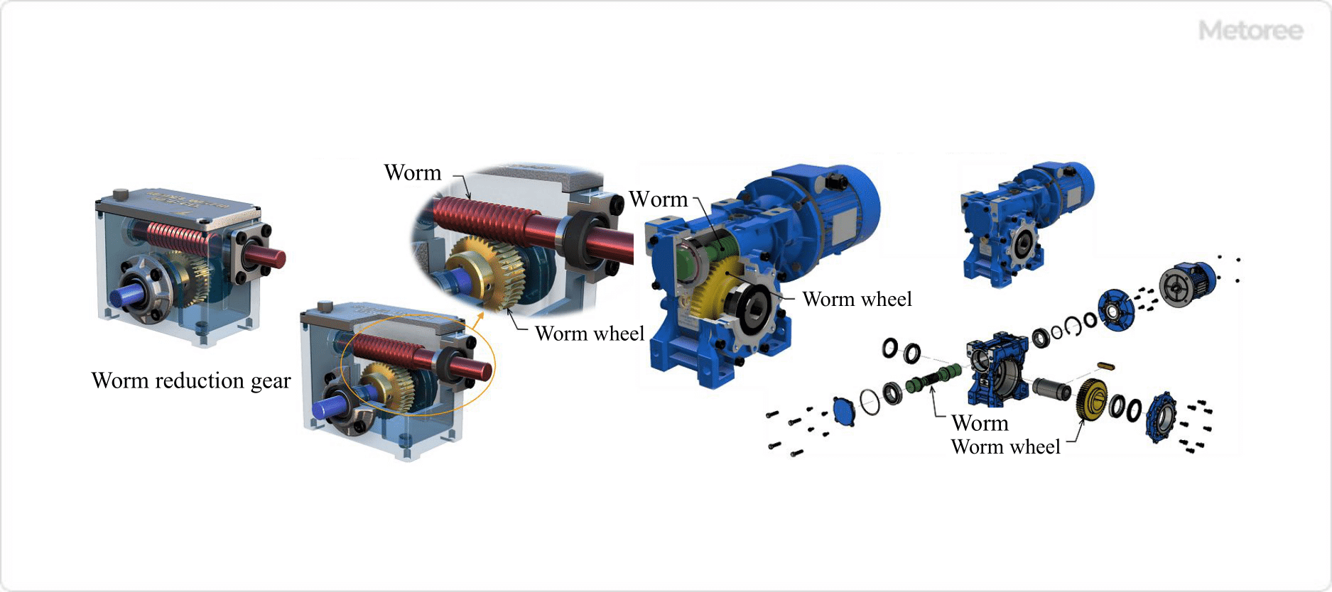
Figure 1. Structure of worm reduction gear
Applications of Worm Gear Speed Reducers
Worm gear speed reducers, like other reduction gears, are capable of moving large objects with minimal force. As a result, they are commonly used in factory equipment and machinery for power transmission.
Specific Applications of Worm Gear Speed Reducers include:
- Driving equipment for presses and rolling mills
- Elevator and escalator driving equipment for medium- and low-speed elevators and escalators
- Drive equipment for conveyors
Worm gear speed reducers find use across various industries and applications, particularly in the following situations:
- When Noise Reduction Is Required:
Worm gear speed reducers are employed in noise-sensitive environments due to their inherently low noise levels. - When Quick Stopping Is Necessary:
Elevators and lifts that require precise and immediate stopping action utilize the self-locking mechanism of worm gear speed reducers. - When Dealing with Impact Loads:
Worm gears, made of soft materials with low hardness such as copper alloys, can absorb shock, making them suitable for applications like rock crushers. - When Space Is Limited:
Worm gears are used in conveyors, packaging equipment, and other machines that require high torque and can be installed in a space-efficient manner.
Principles of Worm Gear Speed Reducer
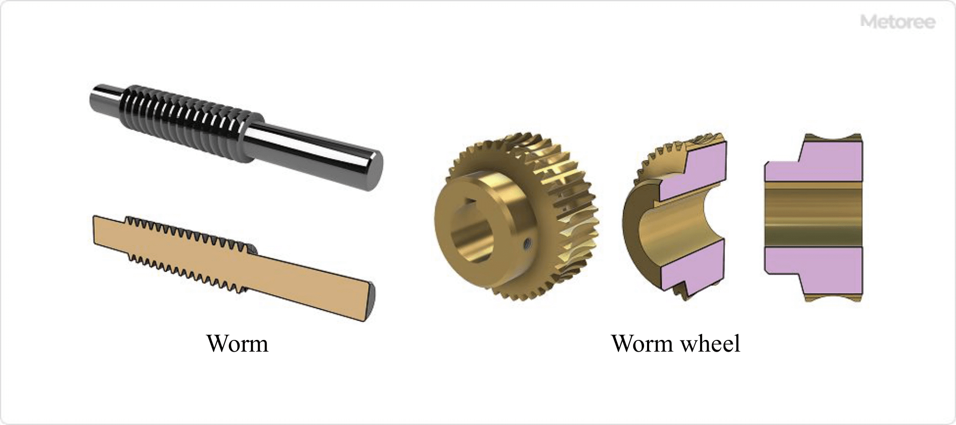
Figure 2. Principle of worm gear
A worm gear speed reducer employs a gear mechanism consisting of a worm (worm shaft or worm axle) and two types of worm wheels.
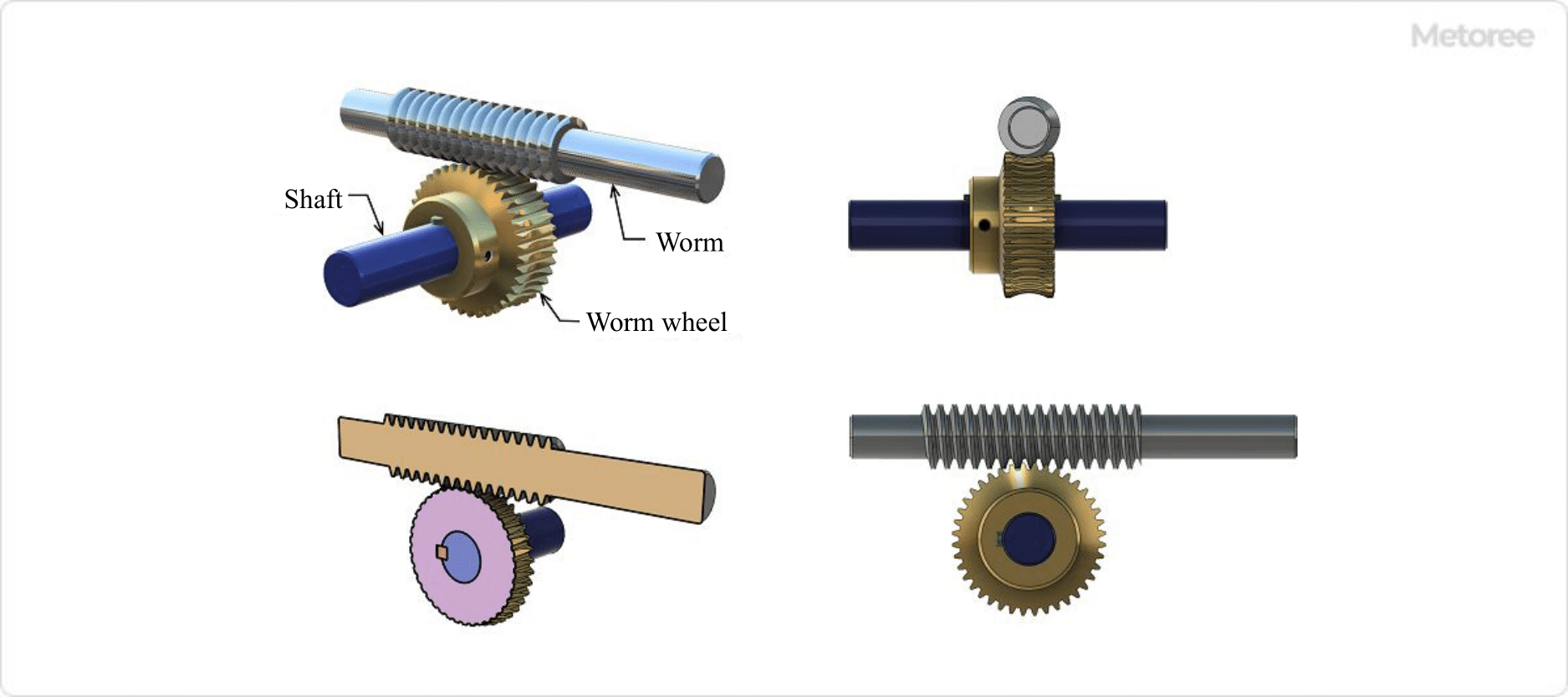
Figure 3. Worm gear assembly
The worm, a type of screw gear, rotates to push the teeth of the worm wheel, causing it to rotate as if a wedge is being driven into it. When the worm (input side) completes one revolution, the worm wheel (output side) advances by one tooth.
In this context, one set of worm teeth equals one tooth. For example, a worm with two worm teeth means that one rotation of the worm results in a two-tooth rotation of the worm wheel.
The reduction ratio of a worm gear can be calculated as follows:
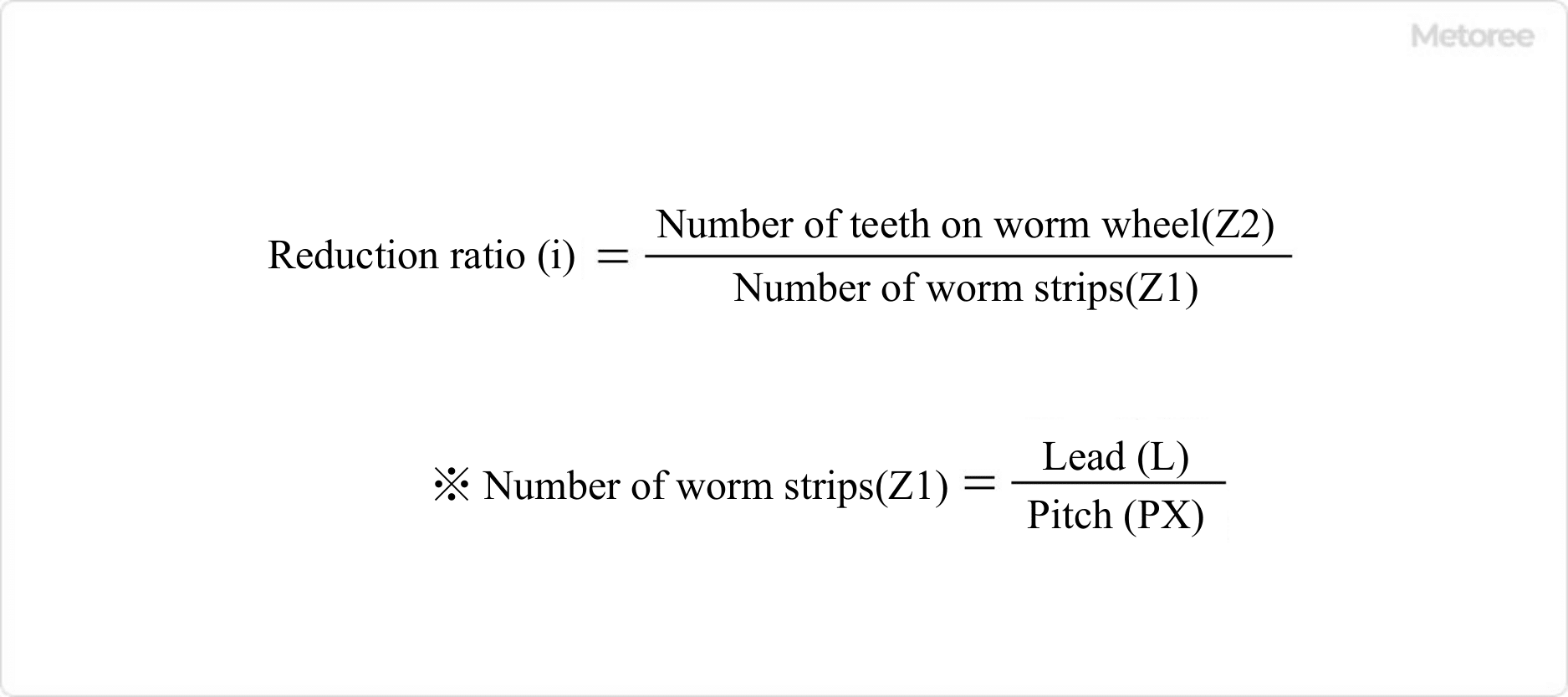
Figure 4. Reduction ratio of worm gear
Refer to Figure 5 below for worm dimensions.
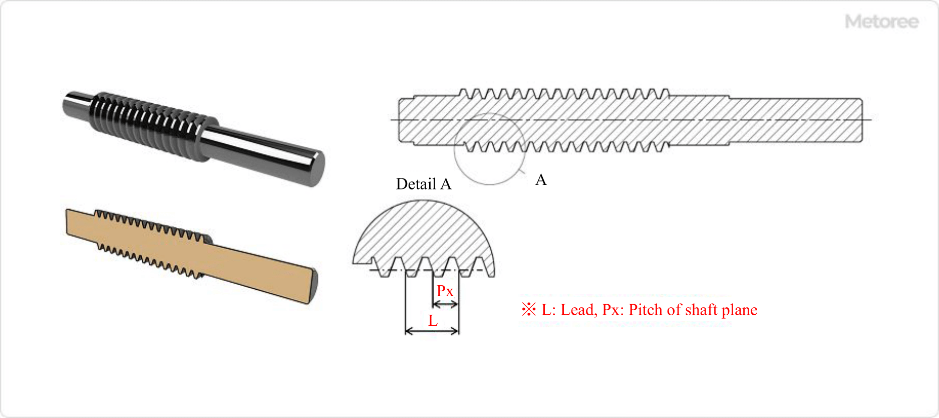
Figure 5. Worm dimensions
The worm gear can rotate in both directions (clockwise and counterclockwise when viewed from the input shaft side). This direction can be determined by selecting the right-hand or left-hand twist direction for the worm. The same rotation of the worm will result in the opposite rotation direction of the worm wheel. Refer to Figure 6 below for the worm twist direction and worm wheel rotation direction.
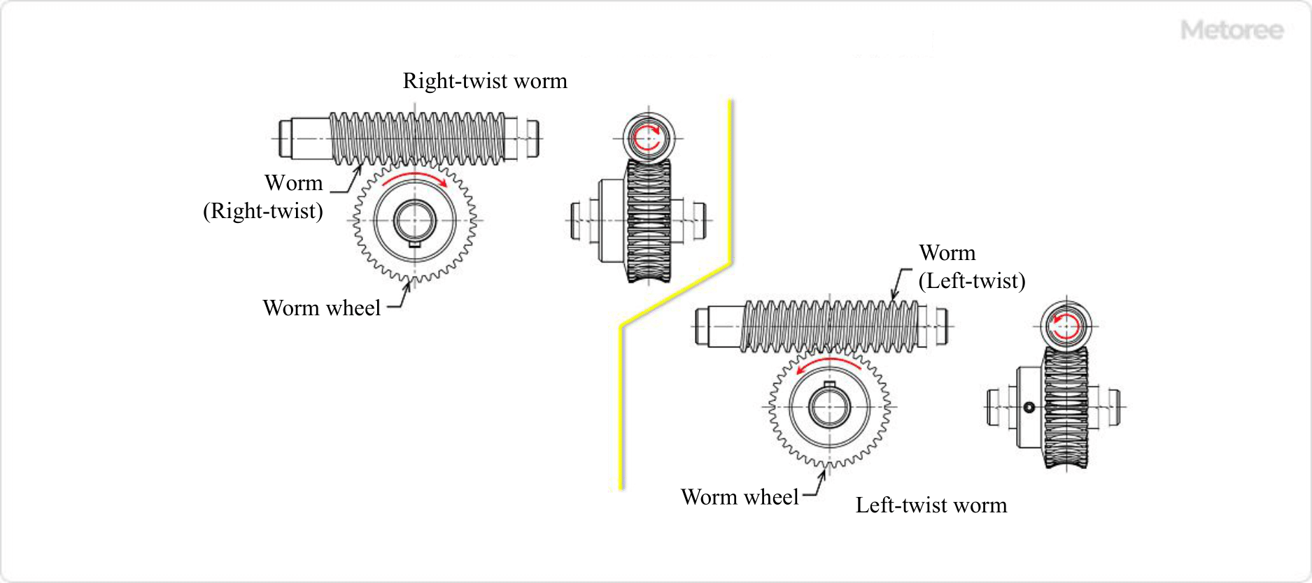
Figure 6. Direction of worm twist and worm wheel rotation
Features of Worm Gear Speed Reducer
A worm gear speed reducer possesses six significant features:
1. High Reduction Ratio
Single-stage gears (comprising one worm and one worm wheel) can achieve high reduction ratios, reaching 1/60 or even 1/120 for specialized gears.
2. Orthogonal Rotating Shafts
The input and output shafts are orthogonal to each other, meaning they lack a coaxial direction.
3. Arbitrary Rotation Direction
The direction of rotation for the output shaft, connected to the worm wheel, can be altered by selecting either the left or right worm twist direction.
4. Freedom of Shaft Arrangement
Input and output shafts can be installed in four directions on one or both sides.
5. Self-Locking Effect
The worm side (input shaft side) can rotate the worm wheel side (output shaft side), but the reverse is not true, thanks to the self-locking effect.
6. Low Vibration and Low Noise
The meshing of the worm and worm wheel provides greater slippage due to linear contact, resulting in lower noise and vibration compared to spur gears, bevel gears, or other rolling transmissions.
One drawback of worm gear speed reducers is their large contact surface on the meshing tooth flanks, which can lead to seizing. To mitigate this, the worm is typically made of alloy steel or other hard materials that undergo heat treatment, while the worm wheel is crafted from copper alloy, cast iron, or other low-hardness materials to reduce friction.