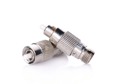
What Is an Attenuator?
 An Attenuator is a component that attenuates an input signal to a desired and appropriate level. It is sometimes abbreviated as ATT, an acronym for Attenuator.
Attenuators are mainly used in electronic circuits, but in a broader sense, they refer to any device that reduces a physical quantity. For example, an optical fixed attenuator, a device that adjusts the optical power level in an optical fiber communication network to an appropriate range, is a type of attenuator.
Attenuators are available in two types: fixed attenuators and variable attenuators. Variable attenuators can reduce the input signal to any desired level while maintaining the impedance matching of the signal line.
Attenuator attenuation is usually expressed in decibels (dB).
Uses of Attenuator
Attenuators are mainly used in industrial applications, such as measurement systems in the field of industrial measurement, various communications equipment, and radar equipment.
In consumer applications, attenuators are used in the volume control mechanisms of some audio amplifiers.
Another major application of attenuators is incorporating them into the input terminal side of power meters used to measure high-frequency power. When the signal input from the receiver is at a fairly high level, the purpose is to attenuate it to an appropriate level before inputting it to a high-sensitivity power meter.
Principle of Attenuator
Variable resistors are generally used to adjust the signal level in electronic circuits, but changing the resistance value also changes the load resistance of the amplifier. If the output impedance of the amplifier is sufficiently small, the change in load resistance can be ignored. However, in transmission lines where impedance matching is a prerequisite, the impedance matching is broken when the resistance value changes, and this causes an obstacle to signal transmission.
On the other hand, an attenuator is characterized by the fact that the combined resistance of the attenuator and load is equal to the resistance of the load alone when viewed from the amplifier’s output terminal. In other words, since impedance matching is maintained in attenuators, no distortion of signal waveforms occurs even in high-frequency circuits.
The basic circuit configuration of an attenuator consists of three resistors connected in a T-shape and a π-shape, and the specific resistance values of T- and π-shaped attenuators can be calculated relatively easily by determining the characteristic impedance and voltage attenuation. The current value flowing through each resistor can also be calculated, making it possible to determine the power consumption of the resistor.
Since attenuators consume power when attenuating signals, they always generate heat. Therefore, care must be taken to use the attenuator at or below its rated power. In particular, since the amount of heat generated by an attenuator that handles a large amount of power will be large, it is recommended to consider the use of a power attenuator with a heat sink attached.
Types of Attenuators
1. F-Type Attenuator
Attenuators are commonly used in antenna signal transmission systems, etc. The F-type attenuator refers to the 75-ohm F-type connector used in broadcasting equipment such as televisions and communication equipment.
Other types of connectors include the N-type and BNC-type used in measuring instruments and other equipment, and the M-type used in amateur radio. Attenuation levels of 3dB, 6dB, 10dB, and 20dB are generally used in many cases.
2. F-Type Attenuator for Screw-Fastening Terminals
A screw-fastening terminal has a screw-fastening terminal on one side and a male F-type connector screw on the other side. Attenuators with F-type terminals for screw terminals used to be widely used in the past, but they are not used very often these days.
The reason for this is that screw terminals are imperfectly shielded, and unwanted signals from the outside can easily enter.
3. Constant Impedance Type Attenuator
The internal circuit of a constant-impedance attenuator is, as described in the previous section, a T-type attenuator or π-type attenuator consisting of three resistors. It is either a 50-ohm or 75-ohm system, or a 600-ohm system, depending on the impedance of the transmission line.
Using a constant-impedance type attenuator provides accurate attenuation and maintains impedance matching. It prevents signal reflections and ensures stable signal transmission.
4. Constant-Impedance Type Step Attenuator
The fixed-impedance type step attenuator allows easy adjustment of the signal level attenuation with a switch or other means. Spectrum analyzers and signal generators use fixed-impedance type step attenuators.
5. Variable Impedance Type Attenuator
As mentioned above, an attenuator is a constant impedance attenuator. An impedance-variable attenuator is sometimes called an attenuator. It is mainly a simple resistor-split type attenuation circuit with a high impedance on the input side and a low impedance on the output side in general.
For low-frequency electrical signals such as audio signals, there is no problem with this type of attenuator because reflected signals are almost negligible. However, for high-frequency signals such as TV broadcasts, impedance-variable attenuators cannot be used because they cause mismatch.