What Is Finite Element Method Simulation Software?
Finite element method (FEM) simulation software is a sophisticated tool that uses numerical analysis to simulate and analyze physical phenomena across various fields such as structural mechanics, fluid dynamics, heat transfer, and electromagnetism.
This method divides a complex domain into smaller, simpler parts, known as elements, to approximate solutions to differential equations that are otherwise challenging to solve analytically. It is particularly adept at analyzing objects of irregular shapes and is widely used for creating versatile, general-purpose simulation programs.
Uses of Finite Element Method Simulation Software
FEM software finds extensive application in several areas:
1. Structures
It’s used for evaluating structural integrity, predicting weld deformation, analyzing crack propagation, and simulating dynamic events like automobile collisions.
2. Electronics
Applications include thermal fatigue analysis of components, design of printed circuit boards, and acoustic modeling of speaker systems.
3. Architecture and Civil Engineering
It aids in the vibration analysis of buildings, the acoustic design of auditoriums, and the structural assessment of dams and ground formations.
4. Fluid and Thermal
The software models fluid dynamics, viscous flow, and thermal behaviors in complex systems, including solidification in casting processes.
Principle of Finite Element Method Simulation Software
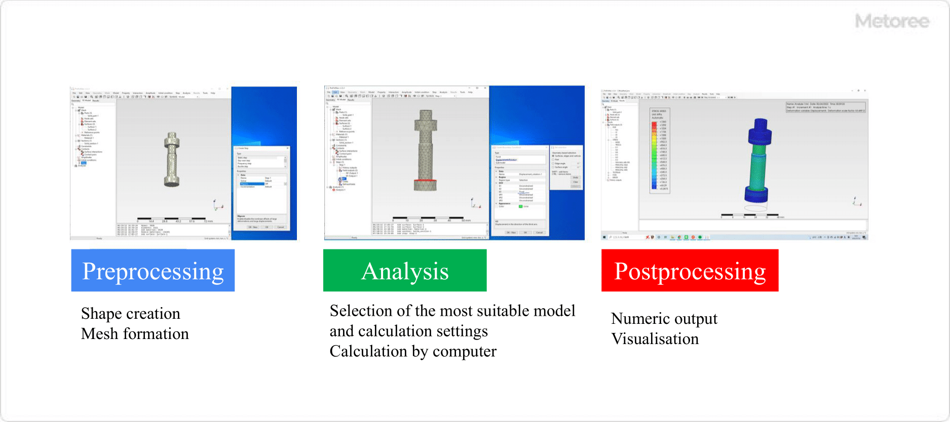
Figure 1: Flow of Finite Element Method Simulation Software
Commercial FEM software typically includes modules for model creation, simulation execution, and post-processing. Integration with CAD software enhances usability for designers.
1. Pre-Processing and Model Creation
Modeling involves creating a geometric representation of the simulation domain, which is then discretized into a mesh for analysis.
2. Simulation Execution
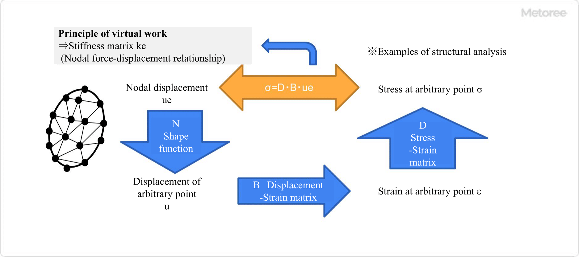
Figure 2: Principle of Finite Element Method Simulation Software
The solver component performs the numerical calculations, applying mathematical models to simulate physical behaviors within the meshed domain.
In this section, we refer to the part commonly called the solver. Nowadays, solvers are equipped with functions for solving more complex models and can perform calculations at higher speeds in response to improvements in computer performance. Solvers use the following procedure to perform calculations.
- The displacement components of the nodes that make up the element are represented by { ue }.
- Create a shape function [ N ] that finds the displacement of any point in the element from the displacement components of the nodes. It is interpolated by a linear or quadratic equation.
- Construct a displacement-strain matrix [ B ] that finds the strain { ε } at any point in the element from the displacement components at the nodes. Differentiate the displacement by the distance.
- Construct a stress-strain matrix [ D ] to find the stress { σ } from the strain { ε } at an arbitrary point in the element. It is obtained from Young’s modulus and Poisson’s ratio and other material mechanics.
- { σ } = [ D ] { ε } = [ D ] [ B ] { ue } gives the stress { σ } from the displacement component { ue } at the nodal point.
- Based on the principle of virtual work (when an object is in balance under an external force, the internal work (strain × stress due to virtual displacement) and the external work (external force × virtual displacement) are equal when the object is subjected to a small virtual displacement), a stiffness matrix [ Ke ] is created.
3. Post-Processing
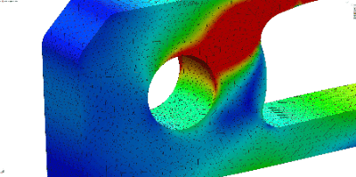
This stage involves visualizing and interpreting the simulation results, often through 3D models and graphs.
Other Information on Finite Element Method Simulation Software
Comparison of Finite Element Method Simulation Software
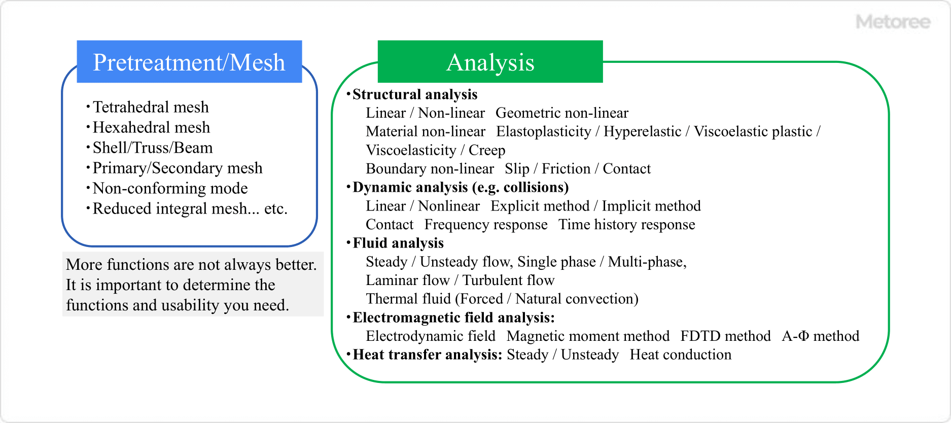
Figure 3: Key Points of Different Functions Depending on Software
There are three primary types of FEM software:
- Designer-oriented software that emphasizes ease of use and integration with CAD tools.
- General-purpose software capable of performing a wide range of complex analyses.
- Specialized software focused on specific applications like electromagnetism or structural analysis.
Users can choose based on their specific needs, balancing ease of use, analytical depth, and cost.