カテゴリー
category_usa

Multi Core Cable

What Is Multi Core Cable?
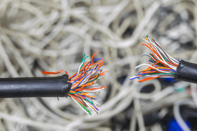
Multi Core CablesMulti-core cable is a cable with two or more internal core wires.

They are used for both signal wiring and power supply applications. Miscellaneous power, such as for home use, often has single-phase circuits. Consequently, power is supplied using two or three cables, including a grounding cable. For power supply to industry, three-phase circuits are used, therefore multi-core cables with three or four cables, including grounding are used.

Multi-core cables with four or more internal cores are often used for signal cables. Multi-core cables with 100 or more internal core wires are sometimes used for telephone lines. For the transmission of weak current signals that are vulnerable to noise, a conductive layer called a shield is sometimes applied as a countermeasure.

Applications of Multi Core Cable

Multi-core cable is always used in the operation of motorized equipment. They are also used in home air conditioners and are one of the most widely used components worldwide. Specific applications are as follows:

  • Power supply wiring for home air conditioners
  • Power supply wiring for industrial pumps
  • Input wiring for sequencers
  • Input wiring for distributed control systems

Electrical circuits require an outward and return path, except when one end is grounded. Therefore, two or more multi-conductor wires are often used.

In large industrial facilities, many sensors such as limit switches are used, each of which sends out signals with about two wires. They are used to reduce labor hours by installing a terminal board near the machine and using several tens of multi-core cables to transmit the signals together to the control system.

Principle of Multi Core Cable

The multi-core cable consists of a sheath, conductor, insulation, and inclusions.

1. Sheath

The sheath is the outer skin that protects the cable. Robust insulators, such as rubber or polyethylene, are used. It is a material provided to protect the cable core from the external environment, such as sunlight and rainwater. In the case of shielded cables, metal shielding such as copper tape is applied between the sheath and the core wire. Sheath refers to a covering.

2. Conductor

A conductor is a metal part that serves as a pathway for electricity. Copper is used because it has low electrical resistance and is less expensive than silver. Another advantage of copper is that it is soft and bendable. There are two types of conductors: single-wire and twisted-wire.

LAN cables may have a single-wire structure, while multi-core cables almost always use a stranded wire structure. The stranded wire structure consists of multiple thin conductors twisted together to form a core wire and has the advantage of high flexibility.

3. Insulation Coating

Insulation coating is a film that insulates conductors. In most cases, vinyl or similar materials are used. The insulation coating may be colored or have core wire numbers printed on it to prevent wiring errors during connection.

4. Inclusions

Inclusions are materials filled between core wires. Paper string or jute is used. They are used to stabilize the arrangement of the core wires.

Types of Multi Core Cable

Multi-core cables are used in different constructions depending on the intended use. The following are typical cables used as multi-core cables.

1. VCT/VCTF

This is a vinyl cabtire cable with a vinyl sheath. It is used for wiring that is moved around, such as for electrical outlets and power tools. These cables are widely used because they are sturdy and inexpensive.

2. 2PNCT/WCT

Rubber cabtire cable with a sheath made of synthetic rubber or natural rubber. Due to the sheath’s sturdiness and flexibility, it is frequently used within cable bearers, among other applications. They are used in more severe environments than vinyl cabtire cables.

3 CVV/CVVS

Multi-core cable is a cable with a vinyl sheath. 10 or more cores are not uncommon, and it is used for control wiring of industrial equipment, etc. CVVS is a cable with a shield layer and is used to transmit analog signals, etc.
カテゴリー
category_usa

Antistatic Sheet

What Is an Antistatic Sheet?

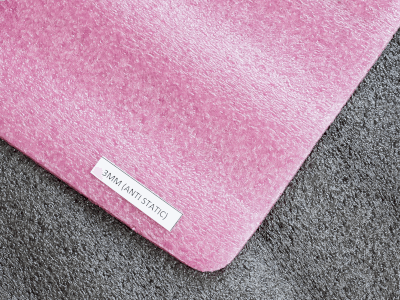
Antistatic SheetsAn antistatic sheet is a sheet that prevents static electricity on the surface of a material. Plastics (films) accumulate static electricity (charging) easily, which can cause electrostatic interference and malfunctions if there are electronic components in the vicinity. It can also cause static ignition of organic materials and adsorption of electrically charged dust.
Antistatic sheets are available in two types: surfactant-added type, in which an antistatic agent floats on the surface, and non-surfactant polymer type, in which the material itself has an antistatic effect.

Applications of Antistatic Sheets

Antistatic sheets are often used as packaging materials for electronic parts, electronic devices, and substrates that are sensitive to static electricity. They are also used as packaging materials for powder and dust-sensitive precision parts.

In addition to films, antistatic plastics are also used to prevent dust and products from adhering to covers in fields requiring a high level of cleanliness, such as semiconductor, medical, and food manufacturing.

They are also used as apron-type protective clothing with sleeves in the medical field.

Principle of Antistatic Sheets

Antistatic sheets with a surfactant are kneaded with an antistatic agent), a substance that has both hydrophilic groups that are easily absorbed by water and hydrophobic groups that are easily absorbed by oil. The surfactant appears on the surface due to the bleeding phenomenon, and the hydrophilic groups adhere to moisture in the air to form a film of water on the surface. This water film contains free electric charges and is conductive. The free charge in this film neutralizes the electric charge, thus eliminating static electricity. Since the antistatic effect is based on the water film that can be formed on the surface, the effect varies depending on the humidity. It is not suitable for long-term use because the effect fades over time.

In the continuous antistatic type, special metal ions are added to the material. These metal ions form a conductive circuit within the plastic as a conductive substance, creating a pathway for static electricity to escape, thereby producing an antistatic effect. In many cases, this type has a transparent blue appearance. It has a semi-permanent antistatic effect and is not easily affected by the surrounding environment, but it is more expensive than the surfactant-added type.

カテゴリー
category_usa

Desktop Dispensing Robot

What Is a Desktop Dispensing Robot?

A desktop dispensing robot, also known as a tabletop coating robot or sealing robot, is a robotic device used to apply adhesives, sealants, coatings, and other liquid materials to specific locations with precision.

Applications of Desktop Dispensing Robots

These robots find applications in various production environments, particularly for coating IC substrates and other surfaces where precise liquid material application is necessary. They enhance efficiency by providing stable and consistent dispensing, improving overall work quality.

Principle of Desktop Coating Robots

1. Dispensing Robot

There are three main types of dispensing robots based on arm motion: vertically articulated, horizontally articulated, and Cartesian robots. Cartesian robots offer simplicity, high positioning accuracy, and lower installation costs.

2. Coating Method

Dispensing methods include the general air pulse method and mechanical methods like the JET method and the volumetric metering method. The choice depends on the liquid material’s characteristics, with the air pulse method offering easy control over dispensed volume.

Features of Desktop Dispensing Robots

1. High Versatility

These robots are adaptable to various production setups, making them suitable for high-mix low-volume production environments.

2. Automation is Possible

They can be easily integrated into automated processes, enhancing production quality and efficiency without significant process changes.

3. Easy to Install in Production Sites

Compact and flexible, these robots can be installed in existing production sites with minimal disruption, accommodating model changes and layout adjustments.

4. High Accuracy

Robust construction ensures high dispensing quality and stability, contributing to improved yield rates and consistent production outcomes.

How to Select a Desktop Dispensing Robot

1. Weight and Axis Load

Consider robot payload and axis load moment to ensure sufficient capacity for the dispensing application and associated equipment.

2. Accuracy and Repeatability

Assess the robot’s motion trajectory accuracy and repeatability to guarantee precise dispensing performance.

3. Controllability

Ensure that the robot’s control system offers precise coordination with the dispensing process, including speed, turning radius, and movement trajectory.

カテゴリー
category_usa

Deodorizing Equipment

What Is Deodorizing Equipment?

Deodorizing Equipment

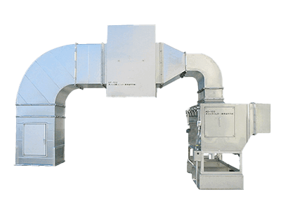
Deodorizing equipment refers to devices designed to neutralize or eliminate unpleasant odors in various settings, ranging from homes and offices to factories and waste disposal sites. Common methods include the use of photocatalysts, ion generators, and specialized systems for handling intense odors from specific substances.

Applications of Deodorization Equipment

These systems are crucial for maintaining air quality, ensuring work safety, and adhering to emission standards in environments dealing with organic solvents, food processing, sewage, and waste treatment.

Principle of Deodorization Equipment

Deodorization can be achieved through decomposition, adsorption, and aromatic methods, each suitable for different levels of odor intensity and operational requirements.

Types of Deodorization Equipment

  • Combustion Method: Utilizes high temperatures to oxidize and decompose odor-causing substances.
  • Cleaning Method: Involves gas-liquid contact with a cleaning solution for neutralization and decomposition.
  • Adsorption Method: Employs materials like activated carbon to adsorb odors.
  • Ion Oxidation Method: Generates oxygen clusters via electric discharge to decompose odors.
  • Photocatalytic Method: Uses ultraviolet light-activated photocatalysts for oxidative decomposition.
  • Ozone Oxidation Method: Brings odorous substances into contact with ozone for decomposition.
  • Dilution Method: Dilutes odors with air and ventilates them out.
  • Biological Deodorization Method: Utilizes microorganisms for natural decomposition.
  • Plasma Decomposition Method: Uses high-voltage plasma-generated active oxygen plasma for decomposition.
  • Chemical Capture Method: Spray a compound solution onto odors for neutralization.

How to Select Deodorization Equipment

To obtain deodorizing effects, it is necessary to accurately grasp the type and nature of the odor and select a deodorization system.

1. Combustion Method

This method can deodorize highly concentrated odors but is expensive in terms of construction and maintenance.

2. Cleaning Method

Effective when substances are specified. Requires large equipment and deodorizer costs.

3. Adsorption Method

Simple equipment, not suitable for high humidity or high-temperature odors.

4. Ion Oxidation Method

Cannot deodorize highly concentrated odors, but is highly safe.

5. Photocatalytic Method

Requires periodic cleaning to restore catalytic function.

6. Ozone Oxidation Method

Compact, but ozone inhalation is harmful.

7. Dilution Method

Effective for all odors at low concentrations.

8. Biological Deodorization Method

Difficult to control conditions, but gentle to nature.

9. Plasma Decomposition Method

Stable, although there are few examples of installation.

10. Chemical Capture Method

Deodorizers can be custom-made except for types that cannot be used.

カテゴリー
category_usa

Single Core Cable

What Is a Single Core Cable?

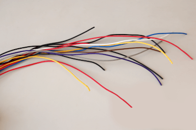
Single Core CablesA single-core cable is a cable that has only one core wire inside.
In most cases, electrical circuits must be balanced. In a single-phase circuit, the current in one phase must be equal to the current in the other phase, requiring two or more cables. Also, in a 3-phase circuit, the sum of the currents in the three phases must be equal. Therefore, in most cases, a single-core cable is of no use, and two or more cables must be used together to form an electric circuit.

Uses of Single Core Cable

There are two main uses for single-core cable:

As a ground wire: A ground wire is a cable that is connected to a grounding pole buried in the earth, and the resistance between it and the earth is kept below 100 ohms. No current flows through the ground wire when a balanced circuit is established. In the event of a wiring or equipment malfunction, a ground-to-ground voltage applied to the equipment may cause an electric shock. Therefore, current is allowed to flow to the ground wire to ensure safety. A single ground wire is used for the purpose of passing current to the earth.

As a power circuit: As mentioned above, two or more wires are generally used in combination for power purposes.

Principle of Single Core Cable

Single-core cable has the same structure as a multi-core cable.

It has an outer sheath and a protective sheath to protect the core wire. The sheath can be made of various materials depending on the application. For low-voltage circuits, inexpensive vinyl is used as the protective sheath.

Single-core cable has excellent heat dissipation performance due to the large surface area of the single core. Therefore, they are mostly used to handle high currents. To improve heat dissipation performance on cable racks and in culverts, cables are not stacked on top of each other but are piled flat whenever possible. A single-core cable used for extra-high voltage distribution lines may also have insulating oil or refrigerant circulating inside to improve heat dissipation.

Single-core coaxial cable may also be used as a cable for cameras. In this case, a shield insulated from the core wire covers the single-core cable, and the core wire and shield are used like a two-core cable. This was once the mainstream usage for analog image signals but is now being replaced by digital signals such as LAN.

カテゴリー
category_usa

Carbon Fiber

What Is Carbon Fiber?

Carbon FiberCarbon fiber is a light and strong fiber composed mostly of carbon.
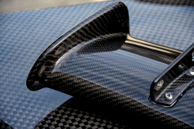
Carbon fiber is made by flame-proofing an organic compound in fibrous form, followed by a high-temperature heat treatment (sintering) at 1,800°F or higher to remove hydrogen and nitrogen atoms from the raw organic compound, resulting in a carbon atom content of 90% or higher.

Applications of Carbon Fiber

Carbon fiber is used in many fields as a substitute for metal materials, taking advantage of its ability to reduce weight while maintaining strength. In addition, its flexibility, electronic conductivity, corrosion resistance, and flame resistance make it suitable for a wide range of applications.

Carbon fiber is rarely used on its own; instead, it is generally used as a composite material combined with materials such as resins, ceramics, and metals. Specifically, carbon fiber is used in aircraft, rockets, and satellites, which require lightweight and high strength. It is also used in surgical orthotics such as artificial limbs, and nursing care equipment such as wheelchairs and nursing care beds, because of its lightness and ease of handling.

Particularly in the automotive industry, carbon fiber can contribute to lower fuel consumption by reducing the weight of vehicles. For this reason, carbon fiber has attracted attention and has been used in racing vehicles since the early days of its development. Carbon fiber also has applications in the sporting goods field, such as golf shafts, fishing rods, reels, bicycle frames, tennis rackets, skis, and snowboards, due to its high strength and elastic modulus.

In the future, carbon fiber is also expected to be used in the construction and civil engineering fields, for example, by attaching carbon fiber sheets to concrete structures to reinforce their earthquake resistance and as a substitute material for cables and steel frames in suspension bridges.

Types of Carbon Fiber

Carbon fiber is classified into two types based on raw materials: PAN-based carbon fiber and pitch-based carbon fiber. Currently, PAN-based carbon fiber is the mainstream, accounting for 90% of the global production of carbon fiber.

1. PAN-Based Carbon Fiber

Carbon fiber made from PAN (polyacrylonitrile) fiber has extremely high strength and modulus and is widely used in industrial fields that require high reliability, such as the space industry, and in more familiar applications, such as leisure goods and sports.

The most common use of carbon fiber is in the industrial field. In the automotive field, it is used in hoods, spoilers, gasoline tanks, and many other parts. It is also used as a substitute material for metal parts, such as leaf springs and gears.

2. Pitch-Based Carbon Fiber

Pitch-based carbon fiber has the feature of adjustable modulus of elasticity. For this reason, it is used in parts that do not require high elasticity and, conversely, in products that do require high elasticity. Pitch-based carbon fiber is further classified into mesophase pitch fiber and isotropic pitch fiber.

Mesophase pitch is a high-performance carbon fiber (HPCF) with high strength and high modulus. Isotropic pitch, on the other hand, has randomly oriented molecules and is optically isotropic.

The resultant isotropic pitch fiber exhibits lower mechanical properties, such as strength and elastic modulus, compared to mesophase pitch fiber. However, it performs similarly in other aspects and is a general-purpose carbon fiber (GPCF) with a lower elastic modulus.

Other Information on Carbon Fiber

How Carbon Fiber is Produced

Carbon fiber can be produced from either PAN-based carbon fiber or pitch-based carbon fiber, depending on the raw material.

  • Flame-Proofing: Fibers are oxidized by heating at a temperature of 400~500°F in air to prevent melting in the subsequent process.
  • Carbon Fiber: Heating at 1500-2900°F in an inert atmosphere removes hydrogen, nitrogen, and oxygen from the fiber.
  • Graphitization: Graphitization of carbon by heating to 4,500~5,400℃ in an inert atmosphere to improve the modulus of elasticity.

1. PAN Carbon Fiber

PAN-based carbon fiber is made from acrylic fiber (PAN fiber). In the flame retardant process, the acrylic fiber molecules are heated at 400-500°F in air to form a cyclic structure. In the carbonization process, the heat of 1,850°F or higher is applied in an inert gas to change the molecular structure of a crystalline carbon structure.

Carbon fiber with high strength and high elastic modulus is produced at the end of the carbonization process. However, graphitization, in which a heat of 3,650°F or higher is applied, produces graphite fiber with slightly lower strength but high elastic modulus.

2. Pitch-Based Carbon Fiber

Coal and petroleum pitches, which remain after distillation of tar obtained by dry distillation of coal and petroleum, are converted into fiber and sintered. Long fibers are made from the pitch in a melt-spinning process before the flame retardant process, and the precursor fiber is obtained by stabilizing the fibers. The precursor fiber is flame retarded, carbonized, and graphitized in the same manner as PAN carbon fiber to produce pitch-based carbon fiber.

カテゴリー
category_usa

Form Management System

What Is a Form Management System?

A form management system is software that manages forms held by companies and other organizations for a legally specified period.

In recent years, the handling of electronic data has increased with the promotion of telework, and interest in the electronic data management of forms has been growing. Software that is highly convenient and can search, retrieve, output, and distribute past form data immediately when needed is required.

Form management systems can store forms that were previously stored in paper form as electronic data in a batch. Since the design and operation of forms are systematized, significant improvements in operational efficiency can be expected. Some types of systems have workflow functions, which can change part of the business process.

Uses of Form Management Systems

Form management systems are used when you want to improve operational efficiency, reliability, and ease of storage and retrieval. The ability to store form data in the cloud can greatly improve convenience and other functions.

When conducting management activities, it is necessary to create forms in order to keep transaction and accounting records. By law, it is required to keep the forms for a certain period. Because of the possibility of presenting the forms from time to time, they must be properly managed. However, since the management is labor intensive, form management systems are used to make it more efficient.

An internal control report is a document that summarizes the status of a company’s effective and efficient management of its entire organization. Form management systems are used for issuing the audit certification required for the preparation of this internal control report.

Principle of Form Management Systems

A ledger sheet is a general term for documents such as account books and vouchers used by companies and sole proprietors in the course of management. They are created to keep records of transactions and accounting records that occur in the course of management activities. They are classified into two categories: “ledgers” such as journal books and sales slips, and “vouchers” such as payment slips and collection slips.

Some of the ledgers and vouchers must be kept for the length of time determined by local laws. The manner in which the forms are managed is important because failure to manage them properly and present them during a tax audit could result in a penalty.

In principle, forms must be managed on paper, but it is possible to store them as electronic data by submitting an application to the tax office in advance and receiving approval. Form management systems, which centrally manage all aspects of forms from design to operation, can also reduce operational burdens, manage trails, and provide security measures.

Other Information on Form Management Systems

Functions of Form Management Systems

Form management systems provide various functions, such as storage, retrieval, classification, output, and distribution of electronic data forms. Electronic data can be handled in formats such as Excel, Word, and PDF, or output in CSV. Therefore, the system can also be linked with other data management systems to enable automatic storage of electronic data.

The form management system’s delivery function can send and receive forms by e-mail or fax, or deliver them on the web using the system’s own cloud. Since the data handled includes confidential information, it is a general rule that the data be encrypted before delivery.

Encryption is a process to prevent unauthorized viewing of data by third parties other than the parties concerned. Generally, the stored electronic data is locked with a password, and then the password is combined (unlocked) by contacting the parties individually.

カテゴリー
category_es

Motores CC

¿Qué es un Motor CC?

Motores CC

Los motores de corriente continua (CC) son motores que funcionan con una fuente de alimentación de corriente continua. A menudo se les llama motores de escobillas debido a la presencia de escobillas en su diseño.

Es importante entender la diferencia entre corriente continua (CC) y corriente alterna (CA). Una fuente de alimentación de corriente continua se caracteriza por tener una dirección constante de flujo de corriente, mientras que una fuente de alimentación de corriente alterna cambia su dirección de manera cíclica. En inglés, “DC” significa “Direct Current” (corriente continua) y “AC” significa “Alternate Current” (corriente alterna). Por lo tanto, cuando hablamos de motores CC, nos referimos a aquellos que utilizan una fuente de alimentación de corriente continua.

Usos de los Motores CC

Los motores CC se utilizan ampliamente tanto en aplicaciones industriales como generales. Para uso general, se utilizan en juguetes de radiocontrol y modelos de coches. El popular mini 4×4 del pasado es un ejemplo típico de juguete que utiliza un motor CC: los motores CC se utilizan a menudo en juguetes por su construcción sencilla y barata y porque pueden alimentarse con pilas secas.

En aplicaciones industriales, los motores de CC se han utilizado en motores de trenes desde el siglo XIX. En los últimos años, se han utilizado en motores de vehículos eléctricos y motores de rotación de discos duros.

Principio de los Motores CC

Dentro de un motor de corriente continua (CC), se encuentra un rotor en el centro con una bobina enrollada a su alrededor, rodeado por un estator que presenta polos magnéticos polarizados en N (norte) y S (sur).

Cuando se aplica corriente al motor CC, se crea un campo magnético en la bobina siguiendo la ley de Fleming. Si los polos magnéticos del rotor y el estator tienen la misma polaridad, se genera una fuerza de repulsión; si tienen polaridades opuestas, se produce una fuerza de atracción que hace girar el rotor.

Al invertir la corriente que fluye a través del rotor, se modifican las fuerzas de atracción y repulsión, las cuales se repiten de forma alternativa para impulsar el giro del rotor en una dirección determinada. La potencia requerida para la magnetización se suministra mediante una escobilla conductora en contacto con una parte llamada conmutador.

Gracias a su estructura sencilla, los motores CC pueden fabricarse con un alto rendimiento de par de salida a un bajo costo. Sin embargo, dado que el conmutador y las escobillas entran en contacto mientras giran, estas últimas tienden a desgastarse. Por lo tanto, en los motores CC con escobillas pequeñas, la vida útil de las escobillas coincide con la vida útil del motor.

Tipos de Motores CC

Los motores de CC de imanes permanentes y los motores de CC de campo electromagnético son los principales tipos de motores de CC, aunque en los últimos años también existen motores de CC sin escobillas.

1. Motores CC de Imanes Permanentes

Los motores CC de imanes permanentes utilizan imanes permanentes en el estator. El rotor es un electroimán formado por un núcleo de hierro y una bobina. Como el estator no necesita ser energizado, la estructura es sencilla y fácil de controlar. 

2. Motores CC de Campo Electromagnético

En los motores CC de campo electromagnético, tanto el estator como el rotor son electroimanes. Como el flujo de campo aumenta al aumentar la corriente en el estator, estos motores se han utilizado en motores CC medianos y grandes.

3. Motores CC sin Escobillas

Los motores CC sin escobillas utilizan imanes permanentes en el rotor. El desplazamiento del rotor se lee mediante un sensor magnético y se controla cambiando el campo magnético generado por el estator. Aunque tienen una larga vida útil y son fáciles de mantener debido a la ausencia de escobillas, requieren el uso de una fuente de alimentación específica para motores CC sin escobillas.

Más Información sobre los Motores CC

Diferencias entre los Motores CC y CA

Las diferencias entre los motores de corriente continua (CC) y los motores de corriente alterna (CA) radican en la fuente de alimentación utilizada: los motores CC se activan mediante una fuente de alimentación de CC, mientras que los motores CA se activan mediante una fuente de alimentación de CA.                        A continuación, se detallan las características de cada tipo de motor:

Características de los Motores CC
  • Pueden funcionar con baterías sin necesidad de modificaciones.
  • Exhiben características de rotación estables.
  • Se pueden fabricar a bajo costo.
  • Ofrecen un alto rendimiento en términos de control de par y respuesta estable.
  • Presentan una rotación desigual.
  • Experimentan dificultades para generar tensiones de CC altas, lo cual complica la fabricación de motores de mayor tamaño.
Características de los Motores CA
  • Pueden utilizar directamente la alimentación suministrada por la red eléctrica.
  • No requieren escobillas, lo que implica una construcción sencilla y robusta.
  • Son fáciles de generar tensiones altas y pueden fabricarse en tamaños más grandes.
  • La velocidad de rotación es constante y está determinada por la frecuencia de la fuente de alimentación.
  • Se necesita un equipo VVVF (Variador de Frecuencia y Voltaje) para controlar la velocidad de rotación.

Es importante destacar que, cuando se utiliza una fuente de alimentación de CA para activar un motor CC, se requiere un rectificador o convertidor para transformar la corriente alterna en corriente continua.

カテゴリー
category_es

Sistema Automatizado de Pipeteo

¿Qué es un Sistema Automatizado de Pipeteo?

Los sistemas de pipeteo automatizados son dispositivos que dispensan automáticamente.

La dispensación es el proceso de medir y dispensar líquidos (por ejemplo, muestras o productos químicos) en cantidades fijas. Esta operación puede realizarse automáticamente, por ejemplo mediante un robot, para garantizar un funcionamiento eficaz y preciso.

Los sistemas automatizados de pipeteo también se denominan sistemas automatizados de dispensación de líquidos, sistemas automatizados de pipeteo o estaciones de trabajo de dispensación.

Usos de los Sistemas Automatizados de Pipeteo

Los sistemas de pipeteo automatizados se utilizan para ahorrar tiempo y esfuerzo y evitar errores humanos en tareas sencillas como extraer la cantidad necesaria de muestra líquida o en polvo y dispensarla en el recipiente deseado. Se utilizan en una amplia gama de campos, como la investigación, la alimentación, la clínica (médica y de laboratorio) y el descubrimiento de fármacos.

1. Ciencias Médicas y Farmacéuticas

Los sistemas de pipeteado automatizados desempeñan un papel importante en los sectores médico y farmacéutico. La dispensación de medicamentos y reactivos requiere el suministro rápido de cantidades precisas. Debido a su gran precisión y estabilidad, los sistemas de pipeteo automatizados son indispensables en la producción y la investigación farmacéuticas.

2. Química y Bioquímica

Los sistemas automatizados de pipeteado también se utilizan ampliamente en la investigación química y bioquímica. Al dispensar con precisión cantidades mínimas de reactivos, los resultados de las reacciones y los análisis pueden ser fiables. La alta eficiencia de trabajo también permite a los investigadores procesar más muestras y realizar experimentos más eficaces.

3. Alimentos y Bebidas

El proceso de producción de alimentos y bebidas también ve mucha acción. Se utilizan para operaciones precisas de dosificación y mezcla de ingredientes específicos, lo que permite obtener productos de calidad constante. Además, se aumenta la productividad acelerando las líneas de producción y automatizando tareas.

4. Análisis Medioambiental

El análisis medioambiental requiere la dosificación precisa de cantidades mínimas de muestras, por ejemplo, para analizar contaminantes en el agua o el aire. La gran precisión y reproducibilidad de los sistemas de pipeteo automatizados garantizan unos resultados de análisis exactos.

5. Pruebas y Diagnósticos Médicos

Los sistemas de pipeteo automatizados también son indispensables en pruebas y diagnósticos médicos. En la dispensación de muestras biológicas, como sangre y orina, deben suministrarse rápidamente cantidades exactas. Al igual que en los análisis medioambientales, una operabilidad precisa elimina los errores humanos y las pérdidas de tiempo.

Principios de los Sistemas de Pipeteo Automatizados

Los sistemas automatizados de pipeteado funcionan mediante una combinación de varios mecanismos y sistemas de control. A grandes rasgos, los sistemas automatizados de pipeteado constan de tres componentes: un recipiente para contener la muestra, componentes de suministro como jeringas y tubos para la dispensación, y un ordenador que controla estos movimientos.

El dispositivo lleva incorporado un sistema de control que procesa la dispensación basándose en parámetros preestablecidos. El sistema de control funciona conjuntamente con un mecanismo de medición de alta precisión para medir y controlar con exactitud el volumen de la muestra.

Los motores, bombas y otros mecanismos del dispositivo son activados por los componentes de alimentación de dispensación para aspirar la cantidad necesaria de muestra y dispensarla en el recipiente deseado. En este proceso también se utilizan válvulas y sensores para controlar la velocidad de la muestra, el caudal, etc. Esto garantiza que la operación de dispensación se lleve a cabo con un alto grado de precisión y tiene un efecto extraordinario en la eficiencia.

Además, los sistemas automatizados de pipeteado pueden procesar varias muestras y varios recipientes simultáneamente. El instrumento está equipado con varios canales, cada uno de los cuales tiene la capacidad de dispensar muestras individualmente. Esto aumenta significativamente la eficiencia del trabajo al procesar varias muestras al mismo tiempo.

Cómo Elegir un Sistema de Pipeteo Automatizado

Existen varios tipos de sistemas automatizados de pipeteado, en función de sus prestaciones y características. Por lo tanto, lo ideal es seleccionar el dispositivo adecuado para su aplicación.

Los tres puntos principales a tener en cuenta son el rango de volumen de dispensación, las características de la muestra a utilizar y la precisión y reproducibilidad. Defina cuánto debe dispensarse y compruebe el rango que puede manejar el instrumento.

También es esencial determinar si el equipo puede manipular la muestra adecuadamente, teniendo en cuenta su viscosidad, corrosividad, temperatura y otras características, ya que el equipo adecuado depende de las características de la muestra que se vaya a utilizar. En consecuencia, el rendimiento del equipo se comprueba consultando las especificaciones del fabricante y los valores de evaluación para garantizar que el equipo es preciso y que los resultados de la dispensación se reproducen de forma coherente.

カテゴリー
category_es

Concentradores Centrífugos

¿Qué es un Concentrador Centrífugo?

Un concentrador centrífugo es un dispositivo que aplica fuerza centrífuga a una muestra en solución a presión reducida para evaporar el disolvente y concentrar la muestra.

Generalmente consta de una cámara centrífuga, una cámara de refrigeración y una unidad de descompresión.

Usos de los Concentradores Centrífugos

Los concentradores centrífugos se caracterizan por reducir el punto de ebullición del disolvente de la muestra durante la concentración y por aplicar una fuerza centrífuga a la muestra para evitar la expulsión del disolvente, la formación de espuma, etc. Esto permite reducir las pérdidas de muestra debidas al calentamiento o a la ebullición, lo que las hace adecuadas para la concentración de muestras para microanálisis en las que se utilizan cantidades muy pequeñas de muestra.

Se utilizan para concentrar ADN, ARN y péptidos, y para preparar otras aplicaciones que requieren concentración y secado. También se utilizan en muchas áreas para la concentración de mezclas de disolventes y agua, análisis de residuos, investigaciones toxicológicas y forenses, química combinatoria, análisis de alimentos y análisis medioambientales.

Principio de los Concentradores Centrífugos

Los concentradores centrífugos utilizados para el microanálisis y otras aplicaciones se caracterizan por el uso de los “tres estados de la materia” para concentrar las muestras. Concretamente, el disolvente de la muestra se evapora a presión reducida y a una temperatura inferior a la de las condiciones atmosféricas, se vaporiza y se recoge, y la muestra se concentra reduciendo la cantidad de disolvente de la muestra. Por lo tanto, la configuración mínima necesaria para un concentrador centrífugo es una cámara centrífuga, una cámara de refrigeración y un dispositivo reductor de presión, como una bomba de vacío.

En los concentradores centrífugos, la cámara centrífuga se despresuriza mediante un dispositivo de descompresión mientras la muestra líquida se coloca en la cámara centrífuga. Al reducirse la presión, disminuye el punto de ebullición de la sustancia y, por tanto, el punto de ebullición del disolvente contenido en la muestra en la cámara centrífuga. Por lo tanto, la evaporación del disolvente es posible a temperaturas más bajas que en condiciones atmosféricas.

El disolvente evaporado pasa a la cámara de refrigeración, donde se enfría y se recoge. En este punto, la muestra se calienta, lo que favorece la evaporación del disolvente y evita la congelación del disolvente que se produce durante la despresurización. La presión en la superficie de la muestra en la cámara de centrifugación es la misma que en la cámara de centrifugación despresurizada. La fuerza centrífuga aplicada a la muestra en el concentrador centrífugo crea un gradiente de presión dentro de la muestra, donde cuanto más profunda es la muestra, mayor es la presión.

Por lo tanto, si la presión en la cámara centrífuga está bien controlada, sólo la superficie de la muestra tiene un punto de ebullición bajo presión reducida y sólo la superficie hierve sin hervir el interior de la muestra, evitando así la ebullición eutéctica, donde el interior hierve.

Más Información sobre los Concentradores Centrífugos

1. Concentración de Lodos Mediante Concentradores Centrífugos

Los espesadores centrífugos se utilizan principalmente en ámbitos como el microanálisis, pero en los últimos años también se han empleado en el tratamiento de lodos de depuradora. Entre los lodos de depuradora, los de la primera balsa de decantación se sedimentan con facilidad y pueden espesarse fácilmente por decantación gravitatoria.

Sin embargo, los lodos de la última balsa de sedimentación (especialmente los lodos en exceso) no sedimentan fácilmente, lo que dificulta su concentración por sedimentación gravitatoria. Por lo tanto, los espesadores centrífugos se utilizan como un tipo de método mecánico de espesamiento de lodos (método de espesamiento mecánico). Los métodos de espesamiento mecánico también incluyen los espesadores flotantes a presión atmosférica y los espesadores de filtración tipo cinta.

2. Estructura y Funcionamiento de los Concentradores Centrífugos para Espesamiento de Lodos

Los espesadores centrífugos para el espesamiento de lodos espesan el exceso de lodo mediante la fuerza centrífuga. En este momento, no se lleva a cabo ninguna despresurización. Los espesadores centrífugos para el espesamiento de lodos tienen una estructura en la que el cilindro exterior y el cilindro interior con tornillo giran alrededor de la tubería de alimentación de lodos manteniendo una diferencia de rotación constante entre ellos.

Esta diferencia de rotación se establece, por ejemplo, entre tres y ocho revoluciones, con el cilindro interior con el tornillo girando ligeramente más despacio. Los lodos se introducen primero en el cilindro exterior a través del tubo de alimentación de lodos del espesador centrífugo. Antes de introducir los lodos en el espesador centrífugo, se suelen añadir floculantes u otros agentes.

El cilindro exterior gira a alta velocidad y el lodo es sometido a la fuerza centrífuga, causando la sedimentación y separación debido a la diferencia de gravedad específica entre el agua y los sólidos, lo que resulta en la acumulación de lodo espesado en el cilindro exterior. En este punto, hay una diferencia de rotación entre los cilindros interior y exterior, con el cilindro interior girando ligeramente más lento, por lo que el lodo concentrado depositado es raspado y empujado hacia fuera por un tornillo unido al cilindro interior y descargado.

Este tipo de espesador centrífugo puede utilizarse, por ejemplo, para espesar lodos con una concentración del 1% o inferior hasta una concentración del 4-6%.