カテゴリー
category_usa

Articulated Robots

What Is an Articulated Robot?

Articulated Robots

An articulated robot is a robot with multiple joints in their arms.

The joints perform the following actions:

  • Bending and stretching of the arm
  • Vertical movement
  • Rotation
  • Extension and contraction

Articulated robots have joints that resemble human movements, such as bending and stretching, as well as linear joints unique to articulated robots, such as extension and contraction. This enables them to perform various tasks in place of humans.

3935_Articulated-Robots_多関節ロボット-1.png

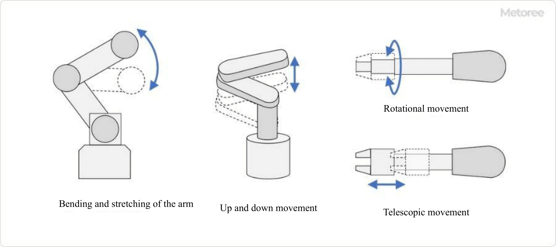
Figure 1. Joint movement of articulated robots

The main types of articulated robots are vertically articulated robots and horizontally articulated robots. Each has a different arm and joint structure, and each specializes in different tasks.

Uses of Articulated Robots

Articulated robots are mainly used to perform the following tasks in place of humans:

  • Heavy-duty work such as lifting heavy loads
  • Work that requires repetition of the same task for a long period of time
  • Work that requires skilled workmanship
  • Inspection work using sensors and cameras

Unlike humans, robots do not get tired and can accurately perform the same task for a long time. Leaving simple tasks to robots allows humans to engage in value-added processes, thereby increasing factory productivity.

In addition, the robot’s ability to reproduce precise movements allows it to accurately trace the movements of skilled workers. This is expected to preserve skill level by transferring the skills of veteran technicians who are about to retire to the robot. With the recent development of AI technology, sensors and cameras can be attached to articulated robots to automate inspections.

Principles of Articulated Robots

Links and joints in a robot correspond to human bones and joints, respectively. The joints are rotational axes and linear motion mechanisms that increase the range of motion of the links, allowing the robot to perform tasks similar to those performed by humans.

Early robots were driven by hydraulic power, but today, motor-driven robots are the norm. Electronic control enables more precise movements.

Other Information on Articulated Robots

1. What Are Vertically Articulated Robots?

Vertically articulated robots are robots whose joints are oriented to move the arm vertically. Vertically articulated robots generally have six axes and can perform horizontal and vertical movements such as X, Y, and Z, as well as rotational movements such as Rx, Ry, and Rz.

Vertically articulated robots are capable of movements similar to those of the human arm.

  • Work that requires an oblique approach, such as welding, painting, etc.
  • Workpiece transfer work in locations with complex entry paths

and other tasks that require a diagonal approach, such as welding and painting.

3935_Articulated-Robots_多関節ロボット-2.png

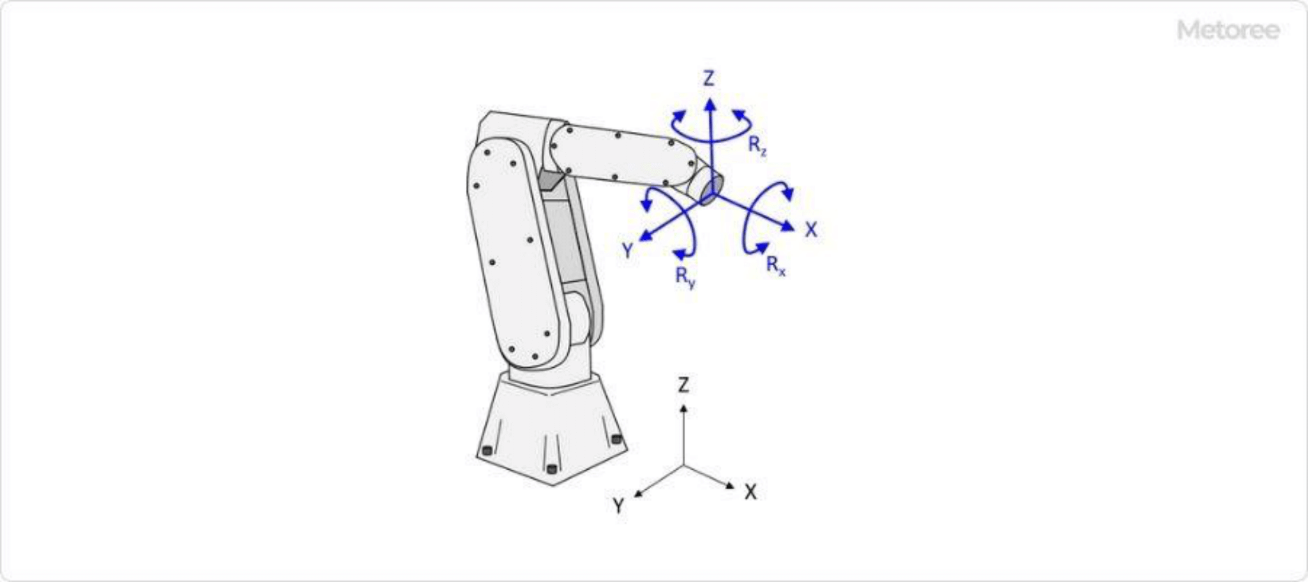
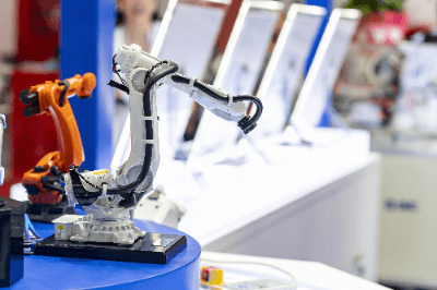
Figure 2. Vertical articulated robot

2. What Are Horizontally Articulated Robots?

Horizontally articulated robots are equipped with three rotational axes that operate mainly in the horizontal direction. They are often referred to as SCARA robots. In addition to the horizontal rotational axes, products with one additional axis for vertical motion are common.

Horizontally articulated robots have the following advantages over vertically articulated robots

  • Quick movement in the plane (X, Y, and Rz directions)
  • Higher rigidity in the vertical direction
  • Low cost

The following are some of the tasks that take advantage of the benefits of Horizontally Articulated Robots.

  • Picking workpieces from a conveyor belt and packing them into boxes
  • Vertical screw tightening work
  • Aligning workpieces in a plane

Horizontally articulated robots and horizontally articulated robots are the same type of articulated robot but have different characteristics, so they should be used according to the work you want to perform.

3935_Articulated-Robots_多関節ロボット-3.png

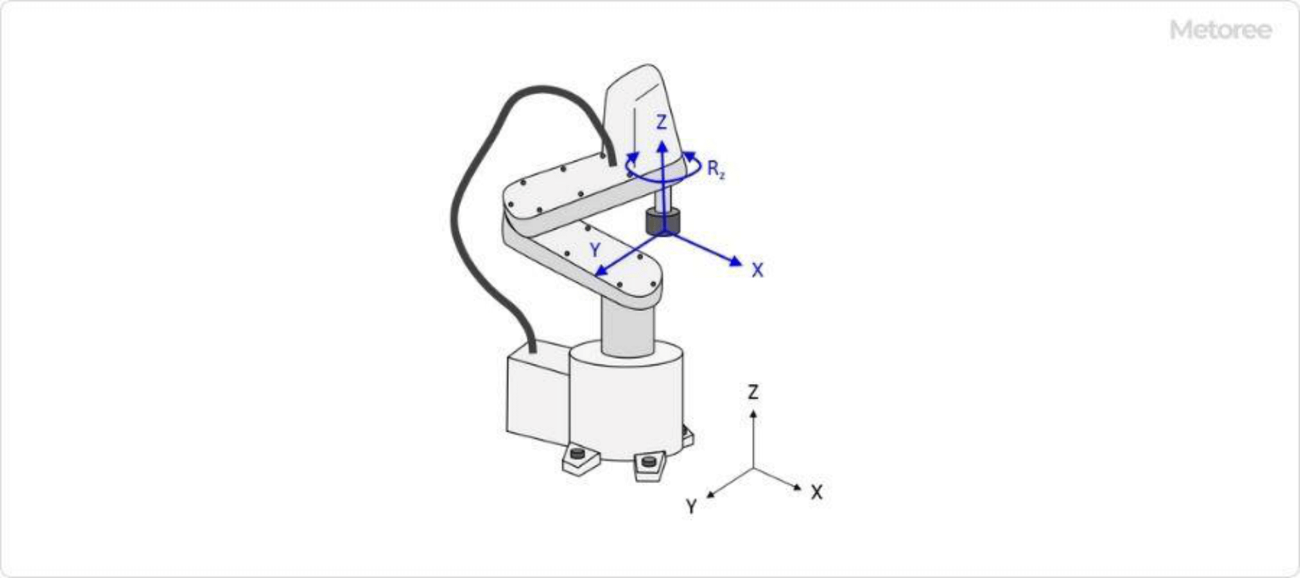
Figure 3. Horizontally articulated robot

3. Low-Cost Articulated Robots

Articulated robots are expensive, traditionally costing tens of thousands of dollars and more, but in recent years, low-cost articulated robots have become available from a variety of manufacturers. These robots are mainly used for electronic construction and programming learning.

Inexpensive robots can be purchased for as little as several hundred dollars, but because they use inexpensive joint structures and motors, their positioning accuracy, repetitive stop position accuracy, operating speed, and durability are much lower. When purchasing a robot, it is necessary to carefully judge whether or not it can withstand practical use.

カテゴリー
category_usa

Withstanding Voltage Testers

What Is a Withstanding Voltage Tester?

A withstanding voltage tester is a testing device used to evaluate the voltage endurance of electrical equipment and electronic components. It ensures that products operate safely within their rated voltage and design specifications. Materials with defects or impurities may lose dielectric strength, leading to the risk of dielectric breakdown when high voltage is applied, potentially causing electric shock or fire. The Electrical Appliance and Material Safety Law sets voltage withstand standards for devices to prevent such disasters. These tests, based on various standards and criteria, assess compliance with the law’s standards.

Uses of Withstanding Voltage Testers

Withstanding voltage testers are employed in a range of industrial fields, primarily for testing electrical products. They are crucial in evaluating the insulation performance of household appliances, like televisions and refrigerators, against overvoltages and voltage fluctuations. In power conversion equipment such as inverters, these tests check insulation capability against high voltages and waveform changes.

In the realm of electronic components like capacitors, withstanding voltage testers are used to assess insulation structures by applying voltages exceeding their rated capacity. For transistors and diodes, the tests verify proper insulation under operational conditions. Additionally, these testers play a vital role in ensuring the safety of medical devices and protecting patients and medical personnel from electric shock risks.

Principle of Withstanding Voltage Testers

Withstanding voltage testers generate and apply high voltages to test objects. Typically employing transformers or power amplifier circuits, they boost low voltages to high levels for application to the test objects. Equipped with measurement circuits and sensors, these testers evaluate the insulation performance by measuring parameters like leakage current and insulation resistance. This confirms the object’s insulation capability and withstand voltage limits. Additionally, these testers often have functions to control the voltage signal’s waveform and characteristics, enabling precise test conditions like sustained voltage application and test duration settings.

How to Select a Withstanding Voltage Tester

Selecting the right withstanding voltage tester involves considering factors such as voltage range, testing standards, and measurement capabilities, all within a budget. Key considerations include:

1. Maximum Withstand Voltage

The tester’s voltage range should align with the test object’s maximum voltage requirements, including the accuracy of voltage control and the applicable voltage type (AC/DC). The equipment’s specifications must be checked for the needed accuracy.

2. Testing Standards and Regulatory Requirements

Test standards and regulatory compliance, ideally to international standards like IEC or industry-specific ones, are crucial. The required voltage level, test duration, and conditions may vary by standard.

3. Measurement Functions

Ensuring the tester has essential measurement functions, such as leakage current and insulation resistance measurements, is important. Protective features like overcurrent shutdown should also be verified.

カテゴリー
category_usa

Desktop Robotic Machines

What Is a Desktop Robotic Machine?

Desktop Robotic Machines

A desktop robotic machine is a compact robot designed to be placed on a desk. These machines are commonly used in factory automation (FA) to replicate tasks performed by workers or assist salespeople in sales applications. Depending on the task, robots may be uniquely developed for specific workpieces or assembled from generic products offered by robot manufacturers. The versatility of these machines is enhanced by the interchangeable end-effectors, allowing them to be adapted for various applications.

Uses of Desktop Robotic Machines

Desktop robotic machines are primarily used in factory automation settings, such as in the manufacturing of automobiles and electrical equipment. They are also employed in processes like resin application, screw tightening, board cutting, and inspection. Choosing the right type of desktop robotic machine is essential, depending on the intended use and the operating environment.

Principle of Desktop Robotic Machines

A desktop robotic machine typically comprises an end-effector for task execution, a moving part like an arm to maneuver the end-effector, and a control unit for overall robot management. The end effector can perform a variety of tasks such as welding, cutting, and assembly, adapting to different application requirements.

For instance, in a production line of automotive drive motors, a desktop robotic machine may follow these steps:

  1. Material arrives at the processing station.
  2. An identification sensor checks the material to be processed.
  3. Based on the sensor’s detection, the machine is instructed to start assembly.
  4. The end-effector jig is replaced for the assembly operation.

Due to its versatility in applications like assembly and inspection, desktop robotic machines are particularly suitable for cell production sites with high-mix, low-volume production.

Types of Desktop Robotic Machines

Desktop robotic machines can be categorized into several types:

1. Vertically Articulated Robots

These robots have a structure akin to a human arm, generally consisting of 4 to 6 axes, allowing free movement in three-dimensional space.

2. Cartesian Coordinate Robots

Cartesian coordinate robots feature a simple structure with a single-axis linear motion unit, often comprising three axes (XYZ).

3. Horizontal Articulated Robots

These robots move their hands (end-effectors) horizontally, usually with 4 axes, including 3 for horizontal motion and 1 for vertical movement.

Other variants include dual-arm models and those designed for specific tasks like welding or cutting with a single arm, or multifaceted tasks like assembly with two arms.

Other Information on Desktop Robotic Machines

1. Safety Measures for Desktop Robotic Machines

Larger robots, such as those with an output power of 80 W or more, typically require safety fences to separate the operator’s work area from the robot’s operating zone. However, recent regulations have relaxed this requirement if safety measures like slowing down or stopping the robot when a person approaches are implemented. Desktop robotic machines, often designed for human collaboration and usually having an output of 80 W or less, don’t necessitate these fences. However, when performing tasks like application work with needles attached to the arm, it’s crucial to use distance sensors and cameras to ensure human safety.

2. Application Example of Desktop Robotic Machine (Pen Plotter)

A pen plotter is a device that transcribes characters from a PC onto paper using a pen. Initially used in mechanical engineering for drawing transcription, pen plotters can be configured with SCARA robots or vertically articulated desktop robotic machines. The latter, with their high movement freedom and rotational capabilities, can replicate handwriting more closely than traditional models.

カテゴリー
category_es

Máquinas de Ensayos de Vibraciones

¿Qué es una Máquina de Ensayos de Vibraciones?

Una máquina de ensayo de vibraciones es un dispositivo utilizado para aplicar vibraciones a componentes o productos con el fin de evaluar su resistencia y características de respuesta ante las vibraciones.

Estas máquinas se utilizan para verificar posibles daños o fallas causadas por las vibraciones, así como para examinar las características de respuesta de los componentes. Las vibraciones pueden generar fatiga en un producto a lo largo del tiempo, por lo que las máquinas de ensayo de vibraciones son empleadas para garantizar su calidad.

El objetivo principal de estas máquinas es evaluar la resistencia a vibraciones de un producto mediante la aplicación de vibraciones sinusoidales o aleatorias. También se utilizan para medir la impedancia mecánica, que representa la respuesta de un sistema mecánico a las vibraciones, determinar frecuencias de resonancia y aplicar contramedidas de vibración.

Usos de las Máquinas de Ensayos de Vibraciones

Las máquinas de ensayo de vibraciones se utilizan para diferentes propósitos, entre ellos:

  • Evaluación de la resistencia a las vibraciones de componentes y productos, así como el rendimiento demostrado en entornos vibracionales. Por ejemplo, se comprueba si piezas de automóviles y componentes electrónicos pueden soportar las vibraciones y mantener su funcionamiento adecuado.

  • Comprobación de los efectos de las vibraciones en productos y sus embalajes durante el transporte. Esto es relevante para productos enviados, como electrodomésticos, equipos de oficina y alimentos.

  • Evaluación de la resistencia de materiales de construcción y estructuras ante terremotos, incluyendo la eficacia de estructuras de aislamiento sísmico y control de vibraciones.

  • Análisis de las características de vibración de álabes de turbinas y vibraciones de torsión en ejes de generadores de turbinas.

  • Medición de la impedancia mecánica en bastidores de máquinas herramienta.

  • Calibración de medidores de vibraciones y sismómetros, entre otros instrumentos.

Principio de las Máquinas de Ensayos de Vibraciones

Las máquinas de ensayos de vibraciones, también conocidas como comprobadores de vibraciones, se clasifican según su sistema de accionamiento en mecánicos, hidráulicos, electrodinámicos y servomotores, cada uno con un principio de funcionamiento distinto.

1. Máquinas de Ensayos de Vibraciones Mecánicas

Este sistema utiliza un motor como fuente de energía para convertir el movimiento de rotación en un movimiento alternativo. Aunque son más económicas que los sistemas hidráulicos y electrodinámicos, las máquinas de vibración mecánicas han sido reemplazadas en los últimos años debido a sus limitaciones en términos de controlabilidad.

2. Máquinas de Ensayos de Vibraciones Hidráulicas

Este sistema emplea la presión hidráulica de una bomba para generar vibraciones. Una válvula de control regula el flujo de líquido para producir el movimiento vibratorio. Es especialmente adecuado cuando se requiere baja frecuencia, desplazamientos largos y alta potencia. Se utilizan comúnmente para vibrar estructuras de gran tamaño, como edificios, sometidas a ondas sísmicas. La frecuencia de vibración oscila entre 1 y 300 Hz.

3. Máquinas de Ensayos de Vibraciones Electrocinéticas

Este método se basa en la fuerza de Lorentz que se genera cuando se aplica corriente eléctrica a un conductor en un campo magnético. Al pasar una corriente alterna por una bobina de accionamiento ubicada en un campo magnético, se genera un movimiento alternativo en respuesta a la corriente. La vibración del excitador es detectada por un sensor y transmitida al controlador, que mantiene la vibración en un valor predeterminado. Una característica distintiva de este método es su amplio rango de frecuencias de vibración, que puede llegar a frecuencias especialmente altas. La gama típica de frecuencias de vibración es de 5 a 3,000 Hz, aunque algunos excitadores más pequeños pueden alcanzar frecuencias más altas, de hasta 40,000 Hz.

4. Máquinas de Ensayos de Vibraciones Servomotores

Este método de ensayo de vibraciones utiliza un actuador lineal con servomotor, que combina un servomotor de corriente alterna con un husillo de bolas. La capacidad de carga de este tipo es inferior a la de los sistemas hidráulicos, y su rango de frecuencias es inferior al de los sistemas electrodinámicos. El rango de funcionamiento se encuentra entre los sistemas hidráulicos y electrodinámicos, con una frecuencia que varía desde 0.01 hasta 300 Hz.

Más Información sobre las Máquinas de Ensayos de Vibraciones

1. Tipos de Pruebas de Vibración

Existen diferentes tipos de pruebas de vibración que se utilizan en las máquinas de ensayos de vibraciones:

Prueba de Vibración Sinusoidal
En esta prueba, la vibración se repite en un período fijo. Hay dos métodos comunes: uno en el que la frecuencia y la amplitud de vibración se mantienen constantes, y otro en el que se varía la frecuencia mientras se ajusta la amplitud de acuerdo con la frecuencia de vibración. Esta prueba se utiliza principalmente para evaluar la resistencia a las vibraciones y también se puede emplear para comprobar la resonancia, la frecuencia de resonancia y las características de respuesta a la vibración de la muestra.

Prueba de Vibración de Onda Aleatoria
En esta prueba, la muestra se somete a una forma de onda de vibración aleatoria sin patrón fijo. Las condiciones de la prueba se especifican en términos de ancho de banda de frecuencia y densidad espectral de aceleración. Se realiza en tres direcciones: arriba, abajo, izquierda, derecha y atrás. Esta prueba proporciona una buena simulación de cómo los productos eléctricos y componentes electrónicos se comportan bajo las cargas de vibración en aplicaciones de transporte terrestre y aeroespacial. Es especialmente efectiva para detectar degradación del rendimiento y fallos mecánicos debido a la acumulación de tensiones, y ofrece resultados de ensayos más representativos del entorno real de uso.

Pruebas de Choque
Estas pruebas consisten en aplicar un impacto pulsante en forma de onda con una aceleración máxima y una duración de acción especificadas a la muestra. Estas pruebas evalúan la resistencia y las características de la muestra frente a situaciones de impacto y choque.

2.Tendencia hacia Máquinas de Ensayos de Vibraciones más Grandes y más Pequeñas

Por un lado, hay una tendencia hacia el desarrollo de máquinas de ensayos de vibraciones cada vez más grandes. Si bien en el pasado los productos eléctricos, componentes electrónicos y piezas de automoción han sido los principales objetos de ensayo, ahora se requieren equipos de ensayo más grandes para aplicaciones como embalajes de carga, piezas para vehículos ferroviarios, industria aeroespacial y construcción antisísmica. Además, la industria aeroespacial exige frecuencias de vibración más altas en comparación con los productos de consumo y automoción, lo que ha impulsado el desarrollo de equipos de ensayo que cumplan con estas especificaciones.

Por otro lado, también existe una creciente demanda de máquinas de ensayos de vibraciones más pequeñas. Un ejemplo son los comprobadores de vibraciones de sobremesa, que se utilizan para detectar fallos de soldadura en placas de circuito impreso, problemas de contacto en conectores y apriete inadecuado de tornillos y tuercas, entre otros. Además, se han desarrollado comprobadores de vibraciones portátiles que se utilizan para evaluar la resistencia a las vibraciones de equipos electrónicos y medir las características de respuesta a las vibraciones de puntos específicos.

カテゴリー
category_usa

Desktop Centrifuge

What Is a Desktop Centrifuge?

Desktop Centrifuges

A desktop centrifuge is a compact version of a standard centrifuge, designed for tabletop use. It uses centrifugal force to separate samples based on particle density. Desktop centrifuges vary in size and complexity, from simple models to those with functionalities akin to larger, floor-mounted units. They accommodate various types of vessels such as microplates, microtubes, test tubes, and centrifuge tubes.

Uses of Desktop Centrifuges

Desktop centrifuges are primarily used for scientific experiments in:

  • Cell culture
  • Blood separation (cells, serum, plasma)
  • Biochemistry (DNA, RNA extraction)
  • Analysis (liquid-liquid extraction)

They are essential in medical settings for immediate separation of plasma or serum post-blood collection.

Principle of Desktop Centrifuge

Desktop centrifuges function by applying centrifugal force to separate substances based on specific gravity differences. This process rapidly separates particles, which would otherwise settle more slowly due to gravity alone. The centrifuge uses a rotor to generate this force, separating substances within samples based on their densities.

Types of Desktop Centrifuge

Desktop centrifuges come in various types:

1. Small Size With Simple Structure and Functions

These centrifuges are used for basic operations like spin-downs and centrifugal filtration, accommodating small plastic test tubes.

2. Tabletop Model With Advanced Functions

Offer similar functionalities to floor-standing models but in a compact form. These models may include cooling and heating options and are compatible with a range of rotor types.

Other Information on Desktop Centrifuge

1. Relationship Between Rotation Speed and Centrifugal Force

Centrifugal force is proportional to the rotation radius and the square of the rotational speed. The conversion between g (gravity) and rpm (revolutions per minute) is essential for precise centrifugal operations.

2. Model Selection Based on Speed and Force Requirements

The selection of a centrifuge model depends on the specific gravity difference of the substances to be separated. Low-speed centrifugation suffices for cell or blood cell separation, while high-speed centrifuges are necessary for DNA/RNA extraction.

3. Precautions for Operation

Proper balance and container strength are crucial for safe centrifuge operation. Post-cooling drying is also important to prevent corrosion and ensure device longevity.

カテゴリー
category_usa

Power Control Panel

What Is a Power Control Panel?

A power control panel is a device crucial for controlling the power supply to motors and machines in various settings. Commonly used in industrial facilities and power plants, these panels manage the start, stop, and speed control of motors. Comprising a power supply unit, control circuits, protection devices, and communication interfaces, they ensure precise motor control and protection. Power control panels often include operational components and display devices for monitoring and adjusting motor performance as needed.

These panels are vital for enhancing safety and operational efficiency by detecting and automatically protecting against abnormal conditions such as overload or overheating. They also facilitate centralized management and remote monitoring.

Applications of Power Control Panels

Power control panels find applications in:

1. Industrial Fields

Used in factories and manufacturing plants for controlling machinery and production line motors, contributing to process efficiency.

2. Power Plants

Essential for machine control in power plants, they manage the operation of large generator peripheral equipment like lube oil pumps.

3. General Construction

In building facilities, they control systems like elevators, escalators, and ventilation systems.

4. Automation Systems

Play a crucial role in automation systems, acting as controllers for power and position control of robots and machines, and interfacing with sensors to enhance automation efficiency and accuracy.

Principle of Power Control Panel

Key components of a power control panel include:

1. Enclosure

Provides a protective housing for control devices and circuits, typically made of a metal box or cabinet.

2. Power Circuit

Supplies power to motors, converting AC power into suitable voltage and current levels, comprising circuit breakers, contactors, and inverters.

3. Control Circuit

Manages motor operation and stopping based on signals from operators and automation systems, including PLCs and control relays.

4. Communication Interface

Facilitates communication between the panel and other systems for data monitoring and control, often featuring Ethernet, serial communication, and fieldbus.

How to Select a Power Control Panel

Selection depends on the system’s capacity, voltage, operation method, and load requirements. This includes choosing inverters or servo controllers for speed and position control, and protection devices like circuit breakers. Complex controls may require PLCs. The design process involves selecting an enclosure that accommodates all components and considering their placement.

カテゴリー
category_usa

Electrical Breaker Panel

What Is an Electrical Breaker Panel?

Electrical Breaker Panels

An electrical breaker panel is a device that distributes electricity to the point of demand.

Generally, they are installed indoors, but depending on the specifications, they may also be installed outdoors.

When an overcurrent or leakage current occurs on the load side, the power supply is cut off to prevent fire or electric shock.

Uses of Electrical Breaker Panels

Electrical breaker panels are widely used in homes and factories.

In homes, they are installed to supply power to electrical outlets and lighting. You may have experienced a breaker tripping when using a hair dryer or microwave oven simultaneously. Electrical breaker panels house the breakers.

They are also installed in factories to supply power to low-voltage equipment. The application is the same regardless of where it is used. When an abnormality such as an overcurrent or ground fault occurs on the load side, the power supply is cut off to prevent fire or electric shock accidents.

Principle of Electrical Breaker Panels

Electrical breaker panels consist of bus bars, breakers, and outer boxes.

The power received from the power company’s transmission lines is branched by the bus bars. Each of the branched power supplies is input to a breaker for overcurrent protection. The purpose of connecting to the breaker is to cut off the power when the outlet on the secondary side is overloaded. To prevent electric shock from touching the inside of the distribution board, a robust outer box protects the charging part.

A breaker is a device that interrupts the power supply when the current exceeds the rated value. When the load current exceeds the rated current, the power supply is cut off to prevent damage to outlets and equipment. A painted iron box or insulating resin is used for the outer box.

Types of Breakers Used in Electrical Breaker Panels

There are three types of breakers used in electrical breaker panels: ampere breakers, ground-fault breakers, and safety breakers.

1. Ampere Breaker

The ampere breaker is an interrupting device that operates when there is an overload in the entire system. It shuts down when the power usage exceeds the contracted amperage with the power company. When this breaker shuts off, the amount of electricity used must be reduced by limiting the equipment used.

2. Safety Breaker

A safety breaker is an interrupting device that operates if an overcurrent flows in one circuit. When this breaker shuts down, it is necessary to reduce the amount of electricity used by restricting the equipment used in the compartment that the breaker is responsible for.

3. Ground-Fault Circuit Breaker

A ground-fault circuit breaker is an interrupting device that interrupts the circuit when it detects a ground fault and prevents disasters such as electric shock. Earth leakage breakers include equipment dedicated to earth leakage functions and equipment that also serves as overload protection. It is generally used for overload protection, but care must be taken when selecting.

Other Information on Electrical Breaker Panels

Maintenance of Electrical Breaker Panels

When a problem occurs with electrical breaker panels, it is necessary to repair the internal parts of the panel. Examples of problems and countermeasures are listed below:

1. When the electrical breaker panels are overheating:
The cause is a loosened screw in the charging section. Check the external appearance and retighten the screws. If the resin box is deformed due to heat, replace the outer box.

2. When the electrical breaker panels’ outer box is damaged:
If the electrical breaker panels’ outer box is made of resin, it may be damaged by impact.

3. Malfunction of the earth leakage breaker or safety breaker:
Leakage breakers and safety breakers may trip due to deterioration over time. In this case, replace the breaker and repair the electrical breaker panels.

4. Disturbance of power supplied to load equipment:
If the power supply is unstable, it may be caused by a loose charging part. Although retightening may restore the power supply, it is also necessary to consider abnormalities in connecting components such as outlets.

When repairing the inside of electrical breaker panels, it is necessary to take sufficient safety measures, such as cutting off the power supply. If you are not familiar with handling electricity, it is safer to request maintenance from a specialized contractor.

カテゴリー
category_usa

Preparative HPLC

What Is a Preparative HPLC?

Preparative HPLCs

Preparative HPLC (high-performance liquid chromatography) is a technique that separates and collects components from a mixture. It’s widely used for purifying main components or collecting trace amounts of impurities contained in samples. Utilizing the same principles as standard HPLC analysis, Preparative HPLC achieves separation and purification based on compound characteristics like chemical structure, molecular weight, and steric structure. This process can be scaled from milligrams to kilograms by adjusting the column size and instrument configuration.

Applications of Preparative HPLC

Preparative HPLC is essential in various fields:

1. Chemical Synthesis Purification

Used to separate and obtain individual components after chemical synthesis, particularly in organic and biochemistry fields where samples often contain impurities and by-products.

2. Side Reaction Analysis

Allows the collection of separate fractions for the analysis of main components and impurities, essential in material and chemical industries for evaluating sample purity and analyzing side reactions.

3. Protein and Macromolecules Purification

Employed in biological fields for purifying proteins and macromolecules, using size-exclusion chromatography columns for precise fractionation.

4. Natural Product Purification

Utilized for extracting specific compounds from complex natural product samples, often employing reversed-phase columns for high-resolution separation.

Principle of Preparative HPLC

Preparative HPLC operates similarly to analytical HPLC, separating compounds based on their interaction with the stationary phase in the column. Columns packed with porous silica gel or functional group-modified silica gel facilitate the separation of components based on their physicochemical properties as they pass through the column.

Other Information About Preparative HPLC

1. Stationary Phases (Normal and Reversed Phase)

The stationary phase function varies depending on its composition. Normal phase mode uses silica gel with organic solvents, while reversed-phase mode, typically employing C18-modified silica gel, separates substances based on their hydrophilic or lipophilic nature.

2. Fraction Collector Integration

Preparative HPLC can be coupled with a fraction collector to separate and collect eluates at specific times, allowing for the concentration and purification of target products.

3. Recycling System

A recycling preparative HPLC system uses a switching valve to pass eluates through the column multiple times, enhancing separation efficiency. This setup mimics the effect of a longer column, providing better resolution but requiring a dedicated device.

カテゴリー
category_usa

Photoacid Generator

What Is a Photoacid Generator?

Photoacid generators (PAGs) are compounds that release acid upon exposure to light, such as ultraviolet (UV) light. This acid then catalyzes reactions, commonly used in photocation polymerization initiators and photoresists for photolithography. Sulfonium salts are typical PAGs, with epoxy resins as a frequent curing material. The reaction initiation by PAGs is controlled by specific light irradiation, not occurring under normal room lighting conditions.

Applications of Photoacid Generators

PAGs have widespread applications, notably in curing photo-curable resins and photolithography, with growing demand due to advances in resin applications and photolithographic technology.

1. Curing of Photo-Curable Resins

In the curing process of photo-curable resins, PAGs trigger polymerization reactions upon light exposure, hardening the resin. This technology is applied in coatings, can paints, and 3D printing materials, with epoxy resins being a common choice for their strong bonding properties and resistance to corrosion and electricity.

2. Photolithography

PAGs serve as photoresist materials in photolithography, critical for semiconductor and LCD production. They produce acid when exposed to patterned light, etching a substrate surface to create a desired pattern. Recent developments include chemical amplification types, where the generated acid acts as a catalyst for further reactions.

Principle of Photoacid Generators

PAGs consist of onium compounds, such as sulfonium and iodonium ions, that absorb light and subsequently generate acid. Upon light absorption, these compounds undergo a process where the cationic part releases an electron, and the anionic part gains an electron, leading to acid production. This acid initiates polymerization reactions, transforming monomers into polymers or other target compounds.

Types of Photoacid Generators

1. Onium Compound Type

Onium compound PAGs, including sulfonium and iodonium salts, are preferred for UV-curable resins and visible light-curable resins, respectively, based on their light absorption characteristics.

2. Nonionic Type

Nonionic PAGs, such as imidosulfonates and oximesulfonates, offer faster curing for UV-curable resins compared to onium PAGs, expanding the range of applications in resin technology.

カテゴリー
category_usa

Stereolithography 3D Printer

What Is a Stereolithography 3D Printer?

Stereolithography 3D Printers

A stereolithography 3D printer is a 3D printer that utilizes the stereolithography method.

The stereolithography method is a technique for creating three-dimensional structures by curing and layering a material, which is cured by exposure to ultraviolet light, layer by layer. The material used is usually a liquid light-curable resin such as epoxy or acrylic resin.

Stereolithography 3D printing is the oldest of all the 3D printing technologies currently in practical use and is the most widely used method in the industry.

Uses of Stereolithography 3D Printers

Stereolithography 3D printers are employed for verifying designs, creating master models, and producing molds.

Due to their capability to produce highly precise, smooth-surfaced objects, stereolithography 3D printers can also be used for manufacturing final products.

The choice of printer types and materials depends on the intended use.

Principles of Stereolithography 3D Printers

In the optical fabrication method, 3D data is loaded into the printer, and the liquid resin is irradiated with ultraviolet light to create the model.

The process begins by creating the first layer, where the resin is cured by irradiating a laser beam onto a tank filled with light-curing resin liquid. Subsequently, the resin is lowered by one layer from the cured stacked surface, and the next layer is cured in the same manner. This process is repeated to build the model layer by layer.

Precise modeling can be achieved by setting a thin layer thickness, while thicker layers allow for faster and more efficient modeling.

Types of Stereolithography 3D Printers

There are several types of stereolithography 3D printers.

Here is a description of typical modeling methods.

1. Classification of Stereolithography 3D Printers Based on Modeling Direction

Stereolithography 3D printers can be classified into two types based on the direction in which modeling proceeds:

  • Free surface method: Light is directed onto the modeling object from above, and modeling proceeds by stacking cured layers.
  • Hanging method: The modeling object is suspended, and light is irradiated from below to advance the modeling.

Stereolithography-3D-Printers_光造形3Dプリンター-1

Figure 1. Classification based on modeling direction

2. Classifications of Stereolithography 3D Printers by the Way Light Is Applied

Stereolithography 3D printers can also be classified based on how light is applied. Three representative examples are:

  • Laser scanning method: This method employs a laser-pointer-like light to draw lines of light.
  • Projector method: A single layer of light is produced with a single irradiation.
  • Liquid crystal panel method: Similar to the projector method, light is emitted from a surface, but this method uses a liquid crystal display instead of a projector to irradiate light.

Stereolithography-3D-Printers_光造形3Dプリンター-2.

Figure 2. Classification is based on the way light is exposed

Other Information on Stereolithography 3D Printers

1. Features of Stereolithography 3D Printers

Stereolithography 3D printers have their advantages and disadvantages:

  • Advantages: They can achieve high-precision modeling with smooth surfaces and are capable of relatively rapid production.
  • Disadvantages: Stereolithography equipment and resins are costly, and post-processing is often required.

The light-curing resins used have distinct characteristics, and the choice of resin depends on the intended application. For example, epoxy resin is not resistant to sunlight, while acrylic resin is fragile, making it unsuitable for applications with high forces or durability requirements.

2. Stereolithography 3D Printers Procedure

The use of stereolithography 3D printers typically involves three steps: creation and conversion of 3D data, modeling, and post-processing.

  1. Creation and conversion of 3D data: 3D data of the object to be modeled is created using 3D CAD or a 3D scanner. This data is then converted into STL data and tool path data compatible with the selected 3D printer, which is subsequently loaded into the 3D printer.
  2. Modeling: The stereolithography 3D printer is used for the modeling process.
  3. Post-processing: Immediately after modeling, the surface of the model is cleaned with alcohol or other solvents to remove any uncured resin. Depending on the resin used, secondary curing may be performed to enhance strength. After these processes, support material, which is used to prevent deformation during printing, is removed.

3. Data Handled by Stereolithography 3D Printers

Stereolithography-3D-Printers_光造形3Dプリンター-3

Figure 3. Data handled by stereolithography 3D printers

To proceed with stereolithography 3D printing, three types of data are essential: 3D data, STL data, and toolpath data.

  • 3D data: 3D data can be created using 3D CAD software and 3D scanners. 3D CAD generates 3D data by designing the object on a computer. 3D scanners acquire 3D data by scanning physical objects. In recent years, some systems have allowed users to easily scan objects using smartphones and other devices.
  • STL data: STL data represents 3D data as a collection of triangles, containing information such as coordinates and normal vectors of the triangle vertices. Many 3D CAD software can output STL data, but when creating STL data, it is necessary to check and correct the model to ensure it is not too flawed to be realistically modeled.
  • Toolpath data: Toolpath data contains information on how the 3D printer operates to create the 3D model. The specific toolpath data varies depending on the 3D printer used, and the 3D printer must read this data to model the object.