カテゴリー
category_usa

Bolt Cutter

What Is a Bolt Cutter?

A bolt cutter is a tool based on the principle of leverage and is specially designed to cut wire rods, bar steel, hard copper wire, and soft iron wire.

It produces a very large amount of power just by gripping the handle, allowing even those with a weak grip to cut hard and thick wire rods with ease. Bolt cutters are generally about 300 mm long, but large bolt clippers exceeding 1,000 mm are also available.

Bolt cutters are sometimes called “guard wire cutters” or “bolt cutters,” but the JIS standard designation is bolt cutters.

Uses of Bolt Cutters

Bolt cutters are primarily used to cut hard steel materials in wire or bar form, such as steel bars, hard copper wire, soft iron wire, stranded wire, cable wire, wire, and nails. They may also be used to cut thick padlocked chains and rebar.

Sites where bolt cutters are often used include construction sites, civil engineering sites, and plumbing sites. In addition, bolt cutters are always available as necessities for disaster relief. Small, inexpensive bolt cutters are also available at home centers and are used as DIY tools.

Principle of Bolt Cutters

The bolt cutter consists of a blade and a handle. The mechanism is based on the principle of leverage in two steps, so that the force applied at the end of the handle becomes 20 to 50 times the force at the tip of the blade, enabling easy cutting of hard steel materials.

The bolt cutter has a mechanism for adjusting the gap between the cutting edges. There are two types: an adjustable frame type with an adjustable mechanism at the base of the handle and an eccentric bolt type with an adjustable mechanism on the blade. When cutting a thin wire or soft steel, if the gap between the cutting edges is too wide to cut completely, use the adjusting bolt on the frame or the eccentric bolt to reduce the gap.

Types of Bolt Cutters

1. Classification by Size

Bolt cutter sizes (overall length) are defined by JIS standards and are classified into the following seven types.

  • 300mm
  • 350mm
  • 450mm
  • 600mm
  • 750mm
  • 900mm
  • 1050mm

In addition to those specified by JIS, mini-sized bolt cutters such as 200mm and 250mm are also available.

2. Classification by Cutting Edge Shape

There are two types of cutting-edge shapes: double-edged (center-cut) type and single-edged (clipper-cut) type. The double-edged type has a thicker and stronger blade and can cut harder and thicker materials than the single-edged type. The single-edge type has a flatter cutting surface than the double-edge type.

3. Angular Cutter (Slanted Type)

Bolt cutters are available with a slanted cutting edge, called an angular cutter, which has a cutting edge bent at about 30 degrees. The angular cutter can cut reinforcing steel bars protruding from walls and floors at reinforced concrete construction sites, etc. from the base because the cutting edge can be placed flush with the wall or floor. The angular cutter can also be used as a regular bolt clipper by replacing the blade.

Other Information About Bolt Cutters

Safety Precautions When Using Bolt Cutters

Since bolt cutters cut hard, thick objects, flying debris can cause unexpected injuries. The following three safety measures are important. 

1. Protective Goggles
It is safe to work with safety glasses to prevent injury in the event of flying debris from cutting.

2. Anti-Scattering Measures
Cover the cutting point with a cloth or bag to prevent flying debris. When cutting strands, wrap the vinyl tape around the cut area and cut the entire tape to prevent it from falling apart.

3. Cutting Several Times
If the piece is difficult to cut, do not try to cut it in one pass, but rather cut it several times. If you try to cut with too much force, fragments may scatter easily and damage the blade.

Also, it is easier to cut from the center to the base of the blade, rather than the tip of the blade, because it is easier to transmit force.
カテゴリー
category_usa

Center Punch

What Is a Center Punch?

Center Punches

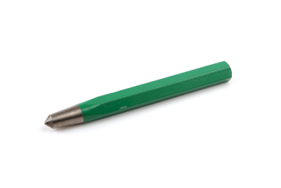
A center punch is a tool used to mark the center of a hole before drilling into a material.

By striking the center punch with a hammer, a small indentation is created on the material’s surface. This indentation serves as a guide for the drill bit, preventing it from slipping and ensuring accurate drilling.

Center punches are essential for tasks requiring precise hole placement, such as assembling rotating machinery like pumps. They come in various shapes and sizes, each suited to specific applications.

Uses of Center Punches

Center punches are versatile tools suitable for use on various materials, including metal, wood, and leather. They are primarily used for:

  • Marking the center of holes to be drilled.
  • Creating guide marks for assembling machinery.

Features of Center Punches

Center punches are specifically designed for marking purposes. Unlike pin punches, which are used to remove pins, center punches have a conical tip. They are typically made of hardened tool steel to ensure durability.

There are several types of pins, including parallel pins, tapered pins, and spring pins. In addition to punching out pins, a pin punch can also be used for insertion to push the pin firmly into the depths.

Types of Center Punches

Center punches come in various types, each serving specific purposes:

  • Pin Punch: Used for removing pins and bolts.
  • Center Punch: Features a 60° tip for creating depressions to guide drill bits.
  • Automatic Punch: Requires no additional tools and is used for drilling holes into workpieces.
  • Drilling Punch: Hollow-shaped punch used for drilling holes in soft materials like metal plates, cloth, and leather.
  • Letter Punch: Engraves letters and numbers onto surfaces.
  • Marking Punch: Also known as a joint punch, used to position dowel holes when joining wood pieces.
カテゴリー
category_usa

Glue

What Is Glue?

Glue

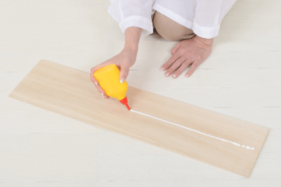
Glue refers to all adhesives produced by Konishi Corporation and is registered as a trademark.

The most well-known type is for woodworking, which is mainly composed of vinyl acetate resin emulsion. Other types of adhesives are used according to the type of material to be bonded.

Compared to other bonding and joining methods, it is quicker to work with, and superior in terms of the types of materials it can handle and resistance to torsion.

Uses of Glue

Glue is used for adhesion in a wide range of applications, including household, construction, and industrial uses.

The most commonly used glue is “wood glue,” which is suitable for bonding wood, paper, cloth, etc. However, other products are used for bonding metals and plastics.

Some materials, such as PE and PP, are not suitable for bonding as they are, so the surface may be treated with heat or acid in advance. Acrylics may be bonded by melting the surface with acrylic resin.

Principle of Glue

In the case of a typical wood glue, vinyl acetate resin, the adhesive component, exists as a colloid in water as a solvent. When the water evaporates, the vinyl acetate hardens and the adhesive action is achieved. This type of adhesive is called a dry-curing adhesive and can be applied to many materials, but it is somewhat inferior in water resistance and heat resistance. It is recommended to bond to smooth surfaces.

Products that are used by mixing two types of ingredients called the main agent and curing agent are called chemically reactive adhesives. Silicone rubber-based and epoxy resin-based products fall into this category. These products have strong adhesive strength and excellent resistance to water and heat, but they are somewhat expensive because they use two types of components, and they require a long time to bond at low temperatures.

Adhesives exhibit three types of interaction on the surface to be bonded. The three types of interactions include mechanical bonding, in which the adhesive penetrates into uneven surfaces and connects objects like a nail; intermolecular interactions between the glue and the surface to be adhered (physical bonding); and structural changes between the glue and the surface to be adhered (chemical bonding).

カテゴリー
category_usa

Micrometer

What Is a Micrometer?

A micrometer is a precision measuring instrument used to gauge dimensional measurements by clamping onto an object.

Typically, micrometers can measure in increments of 0.01 mm, although some instruments can measure down to 1 µm (0.001 mm). It’s often referred to simply as a “mic.” Micrometers come in various types, including outer micrometers, inner micrometers, rod-type micrometers, depth micrometers, etc., each suited for specific measurement tasks.

Most micrometers have a measurement range of 0 to 25 mm or 25 to 50 mm, in 25 mm increments, so it’s essential to determine the approximate size of the object before measurement.

Uses of Micrometers

Micrometers are employed when high-precision measurements are required, often replacing calipers. The type of micrometer used depends on the object to be measured:

1. External Micrometer

Measures the outer diameter and thickness of objects.

2. Internal Micrometer

Measures the inside diameter of objects or the width of grooves or holes.

3. Three-Point Internal Micrometer

Precisely measures the inside diameter by gauging at three points.

4. Rod-Type Micrometer

Designed for measuring the inside diameter of large circles.

5. Depth Micrometer

Used to measure the depth of grooves and holes.

Principle of Micrometers

Micrometers operate on the principle of a precision screw. Rotating the screw clamps the object, and the amount of rotation corresponds to the measured dimension. Most micrometers use a screw with a 0.5 mm pitch, resulting in 0.01 mm increments. Some micrometers can read as fine as 0.001 mm.

To prevent variation in measurements due to the force required to turn the micrometer, a constant-force mechanism, often a ratchet stopper, is employed.

Types of Micrometers

There are various types of micrometers tailored to different measurement needs:

1. Standard Micrometer

Used for measuring external dimensions, often employed in tubular product manufacturing.

2. U-Shaped Micrometer

With a large frame depth, ideal for measuring the thickness of steel plates.

3. Spherical Micrometer

Features spherical surfaces on both the anvil and spindle, enabling precise measurements and accommodating objects of varying thicknesses.

4. Rod-Type Internal Micrometer

Shaped like a single rod, suitable for measuring the inner diameter of large objects.

5. Three-Point Internal Micrometer

Offers enhanced accuracy by measuring at three points, facilitating the detection of inside diameter deformations.

Structure of Micrometers

Micrometers consist of various components, including an anvil, frame, heat shield, spindle, clamp, sleeve, reference line, thimble, and ratchet stop. The object is placed between the spindle and anvil, and the thimble is rotated to measure both sides of the object accurately.

カテゴリー
category_usa

Machining Center

What Is a Machining Center?

Machining Centers

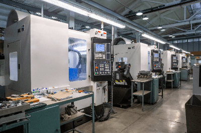
A machining center is a numerically controlled (NC) machine tool that performs various types of machining without the need to change the workpiece.

In addition to the main spindle, which is used to mount tools and provide rotational motion, the machining center consists of an ATC (Automatic Tool Changer) and an index table for fixing the workpiece at various angles.

Uses of Machining Centers

Machining centers are used to process metal, plastic, glass, and other materials, including molds, which are indispensable for molding. Since various tools can be changed automatically, machining with tools such as milling, end milling, drilling, boring, and tapping can be performed in a single process.

In terms of machining freedom, the addition of two rotational axes to the conventional three axes of length, width, and height enables machining with five degrees of freedom. This eliminates the need to lift the workpiece and allows for the production of highly accurate parts.

Principle of Machining Centers

Machining centers are classified into three types: vertical machining centers, horizontal machining centers, and double-column machining centers.

Vertical machining centers have a vertical spindle, and the workpiece is machined from above. Vertical machining centers are compact and the most widely used type. During machining, cutting chips remain on the workpiece and tend to damage the tool’s cutting edges. Measures such as adjusting the tool rotation speed and the amount of cutting oil are necessary to facilitate chip removal.

In the horizontal type, the spindle is horizontal to the ground, and the workpiece is machined from the side. Cutting debris falls to the bottom of the workpiece for easy discharge. Also, a pallet changer that automatically transfers parts can be installed, allowing parts to be machined continuously without the use of human hands, making it suitable for mass production.

The gate type is shaped like a gate when viewed from the front and is suitable for processing large products because the table on which the workpiece is placed is wide and long.

カテゴリー
category_usa

Machine Key

What Is a Machine Key?

A machine key is a machine element inserted into the groove of the mating part of a shaft and gear of a machine tool, etc.

Types of machine keys are described as: “parallel key,” and “semi-round key.” In addition, “double round key,” “double square key,” and “single round key” are specified for the parallel key.

Uses of Machine Keys

Machine keys are essential for power transmission in various applications and fields.

Machine keys are used in the gears on the shaft side of electric motors and pumps, which are the source of power, as well as in mating gears such as gearboxes and pulleys that transmit power to belts.

Machine keys are used in a wide range of fields, including machine tools, construction machinery, food machinery, and other machinery, as well as in vehicle-related fields such as automobiles.

Characteristics of Machine Keys

Machine keys are required to have high strength for the purpose for which they are used. They must also have the characteristics of tenacity, tensile strength, and durability due to their fitting structure, and the ability to be removable as needed.

Machine keys are available in various shapes and materials, including carbon steel for machine structural use such as S50C, copper alloy, stainless steel such as SUS316, tool steel, and titanium, depending on the application.

Furthermore, machine keys need to be removed when replacing worn or damaged gears and pulleys, etc. Since it is difficult to remove machine keys that have been used for a long time, tapped keys are also available to make removal easier.

In addition, machine keys need to be replaced with caution because the position of the key groove on the shaft may determine which machine keys can be used.

The order in which machine keys are inserted differs depending on the shape of the key.

カテゴリー
category_usa

Mirror

What Is a Mirror?

Mirrors

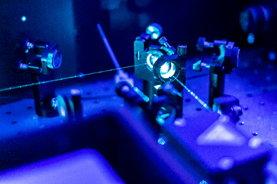
A mirror is a type of optical device that reflects light.

Mirrors are common household items, but a wide range of mirrors exist in the industrial field. For example, there are spherical mirrors with a spherical reflecting surface, toroidal mirrors with different curvatures on the X and Y axes, parabolic mirrors that make all light emitted from a focal point parallel (or, conversely, focus parallel light to one point), and ellipsoidal mirrors that focus light from one point to another.

Reflective surfaces are often made of high-purity aluminum, and thin films of silver or gold are also used, with gold thin films being particularly useful for reflecting infrared light.

Uses of Mirrors

Mirrors are used as dressing and vanity mirrors in homes. Industrially, they are used in optical instruments such as spectrophotometers, photodetectors, and FTIRs as measuring instruments.

As optical equipment for consumer products, they are used in projectors, cameras, CDs, DVDs, and microscopes.

In optical equipment using lenses, mirrors bend the optical path, allowing for more compact designs compared to lenses alone.

Principle of Mirrors

In addition to mirrors, lenses are also used as optical elements in light paths. Unlike lenses, mirrors reflect light in the same way at all wavelengths, avoiding chromatic aberration caused by differences in refractive index with lenses.

Manufacturing mirrors with free-form surfaces has become possible with methods like diamond turning, where aluminum is directly machined with a diamond-turning machine to create mirrors with a wide range of curved surfaces.

Structure of Mirrors

Mirror shapes include flat, spherical, and aspherical mirrors.

1. Plane Mirror

A flat mirror that reflects images in one direction only.

2. Spherical Mirror

A mirror with a surface shaped like a cutout of a sphere. It can be convex or concave.

3. Aspheric Mirror

A mirror with a curved surface other than a spherical surface, such as parabolic mirrors used in reflecting telescopes.

Types of Mirrors

1. Clear Mirror

Standard mirrors used in everyday life, typically 5 mm thick.

2. High Transmittance Mirror

Less bluish than clear mirrors, suitable for beauty salons and boutiques.

3. Moisture-Resistant Mirror

Also known as epoxy mirror, resistant to rust and stains, and suitable for wet environments.

4. Gray Mirror

Dark gray glass is suitable for various environments.

5. Bronze Mirror

Bronze-colored glass is used in restaurants and boutiques.

6. Tapered Mirror

The surface is treated to create an indirect lighting effect.

7. Thin Sheet Mirror

Thin mirror with a thickness of 2-3 mm.

8. Magic Mirror

Appearance changes based on lighting conditions, used for privacy or observation.

How to Choose a Mirror

Durability is crucial; aluminum surfaces are often coated with magnesium fluoride or similar material to enhance durability against UV exposure.

カテゴリー
category_usa

Metal Halide Lamp

What Is a Metal Halide Lamp?

Metal Halide Lamps

A metal halide lamp is a type of high-intensity discharge lamp (HID lamp) that uses a discharge in a mixed vapor of mercury and metal halides. Metal halide lamps are characterized by their high color rendering and high luminous efficiency.

The Minamata Convention on mercury banned the manufacture, export, and import of mercury lamps after 2021, with an exemption for metal halide lamps. As a result, mercury lamps are being replaced by metal halide lamps.

Uses of Metal Halide Lamps

Metal halide lamps and other HID lamps are much brighter than fluorescent lamps and other lamps used in ordinary households. Among them, metal halide lamps offer higher luminous efficiency and better color rendering than other HID lamps. For this reason, metal halide lamps are used for lighting in various indoor and outdoor facilities, such as sports facilities, commercial facilities, exhibition halls, and roads. They are also used as light sources for optical equipment such as projectors.

On the other hand, they cannot be used for emergency lighting because of the time required to turn on and off again. In recent years, they are increasingly being replaced by LEDs due to their longer life span.

Principle of Metal Halide Lamps

Metal halide lamps consist of quartz glass or ceramic tubes filled with mercury and metal halides. The metal halide is evaporated by an arc discharge and dissociated into metal atoms and halogen atoms under high vapor pressure. The collision of the metal atoms and electrons emits light at a wavelength specific to the metal. Iodide compounds such as sodium iodide and scandium iodide are often used as metal halides, and by optimizing the compound materials and mixing ratio, color rendering and luminous efficiency can be improved.

Lighting and maintaining metal halide lamps requires fine control. At the start of lighting, a high-voltage pulse wave is generated using an igniter to cause a discharge. After the lamp is turned on, a ballast is used to control the lamp to maintain a constant voltage and current regardless of changes in ambient temperature or deterioration over time, in order to keep the light of the lamp constant.

カテゴリー
category_usa

Motor Pulley

What Is a Motor Pulley?

A pulley is frequently used in machinery and equipment, automobiles, and other power sources. In the case of a motor pulley in particular, it refers to an integrated roller drive structure that incorporates a motor for driving and a reduction gear for adjusting the motor’s rotation speed inside the pulley.

The roller covering the motor rotates and serves not only as the driving unit of the conveyor belt for transport but also as a safe, silent, and space-saving power source because the drive unit is built in a sealed structure.

Uses of Motor Pulleys

Motor pulleys typically serve as power sources for rotating belts within conveyor systems. They are installed in various locations, with roller types like rubber rollers and magnetic ring rollers being chosen based on the conveyor belt’s requirements. Being a motor, it doesn’t require maintenance such as lubrication.

Motor pulleys in the broad sense of the term also include automatic transmission shifting applications such as CVTs for automobiles. In this case, a mechanism is used in which the position of the belt on the pulley changes in accordance with the acceleration torque and rotation speed for pulleys of different diameters.

Principle of Motor Pulleys

Motor pulleys are powered by a motor, typically operating at a constant speed. To adjust the speed of the belt conveyor, an inverter is employed.

Roller conveyors are machines that convey objects by utilizing the rotation of rollers instead of belts. However, the outer diameters of rollers used for such applications are often relatively small. On the other hand, motors with a large outer diameter and rotational torque are often used for belt conveyors.

Pulleys utilizing V-belts or roller chains are also frequently seen. In this case, the rotation speed can be changed by changing the ratio of the outer diameter of the V-pulley to the belt position. Of course, an inverter can also be used in combination.

In the case of motor-integrated pulleys, the advantage is that the motor fits precisely into the core of the pulley and drives the roller directly through the internal gears without generating any loss, resulting in a very high transmission efficiency to the rotational torque. To improve performance, about 30% of oil is sealed inside the motor pulleys, and some motors also serve to lubricate and cool the bearings.

カテゴリー
category_usa

File

What Is a File?

Files

A file is a tool for grinding an object. More specifically, a file is a tool made of carbon or alloy tool steel with a cutting edge called a “grain” that is swaged or machined into the tool and heat-treated. Filing is the process of machining by grinding flat, curved surfaces and corners with these tools.

The file is selected according to the type of grinding work to be performed on the object. The grit sizes are rough, medium, fine, and oil grit, with subsequent grits representing finer grits.

Uses of Files

Files are used to grind the surface of an object to obtain flatness and precision or to polish a surface to give it a glossy finish.

There are several different types of file grits, which are used according to the material, and the required finishing accuracy.

As an example of how to use different types of files, let us consider the task of creating flatness on the surface of a piece of machinery or equipment.

First, in order to prepare a rough surface initially, a large amount of grinding is done using a rough duplex file. Then, a medium- or fine-grained single file is used to grind the surface finely. In this way, the entire surface is first ground to a rough finish with a large grind and then ground with a fine grind to produce flatness accuracy efficiently.

Characteristics of the Files

Files are characterized by the fact that they can only grind the part that is in contact with the object and to which force is applied. This means that the application of force during grinding must be constant to achieve a clean finish.

For example, consider the operation of using a long, flatboard file to grind the corners of a table into a round shape.

To grind, place the tip of the board files against the corner of the table and move the files as if pushing the handle out. At this time, the corner of the table that is in contact with the board files moves with the pushing motion. The closer the corner of the table is to the handle, the stronger the force applied to the contact surface between the table and the files. This happens because of the principle of leverage between the corner of the table and the board files.

Thus, even if you think you are grinding with the same force, the force applied to the workpiece varies depending on the position of the files in contact with the workpiece. In this case, the corners of the table are not ground with a constant force, resulting in an irregular shape.

Considering that the force applied to the workpiece changes during the grinding process, simply adjusting the force applied so that the same force is always applied will improve the finish of the grinding process.