カテゴリー
category_usa

Computer Aided Design(CAD)System

What Is a CAD System?

A CAD (Computer Aided Design) system is a design method or software that allows design and drafting to be done on a computer, whereas they were originally done by hand on paper.

CAD was developed by American computer scientists in the 1960s and was initially used for aircraft design. Later, it spread to industrial fields such as architecture and automobiles, and is now also used in the apparel industry.

There are two types of CAD systems: 2D CAD systems, which represents drawings in two dimensions, and 3D CAD system, which represents drawings in three dimensions.

There are also two types of CAD systems: general-purpose CAD, which can be used in any field, and specialized CAD, which has functions specific to a particular field, such as architecture, automobiles, and electrical engineering.

A Computer Aided Manufacturing (CAM) system is a tool similar to CAD that creates control programs for manufacturing machines based on CAD design information, and Computer Aided Engineering (CAE) system is a tool that simulates whether a product designed with CAD satisfies target performance and evaluation requirements. Both are used in conjunction with CAD systems.

Uses of CAD Systems

CAD Systems are used in a variety of industries that have a design process as part of their business.

The main uses are as follows:

1. Drawing Creation

CAD systems are used to create drawings for buildings, automotive parts, and any other area where dimensions, shapes, and their ranges need to be specified.

Sharing and editing data with clients and business partners can also help shorten architectural design turnaround time and speed up parts development.

2. Design

CAD Systems can be used not only for structural design, but also for automobile, furniture, and interior design. By using CAD systems, the work conventionally done by designers with sketches can be conveyed in three dimensions.

Unlike sketches, the concept can be conveyed more easily by viewing it from various angles and rotating it on the system screen. 

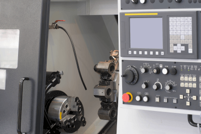
3. Creation of Data for Machine Tools

NC machining is a method of machining metals, wood, and plastics, in which a rotating blade is applied to the workpiece to create the desired shape.

4. Structural Analysis and Simulation

CAD Systems can not only design the dimensions and design of a structure, but also simulate its behavior when force is applied. For example, when designing a chair of a certain shape, it is possible to predict by analysis how much force will be applied to the legs when a load is applied to the seating surface, and whether the legs will be deformed or damaged.

CAE (Computer Aided Engineering) software is used for the analysis.

Principles of CAD Systems

CAD Systems can be implemented more speedily than the work done by hand on paper. It is possible to make the thickness of lines and handwritten text uniform, which tends to cause errors among workers. Drawing corrections can also be made by pinpointing and changing only the relevant areas.

By saving the history of design data, it is possible to go back to previous data and redo the design. In addition, by importing past drawing data, common tasks for similar designs can be reduced, thereby improving efficiency.

In addition, paper-based blueprints are at risk of tearing and ink fading, but CAD system data is free of such risks. Because it is easy to manage, CAD data can be instantly shared with people who are physically separated from each other via e-mail or other means.

Types of CAD Systems

There are two types of CAD systems: 2D CAD and 3D CAD.

1. 2D CAD System

CAD Systems use a computer to create the equivalent of conventional paper drawings: front, plan, and side views based on trigonometry. The drawings themselves are no different from those of the hand-drawn era, but designing on a computer has dramatically improved work efficiency.

2. 3D CAD Systems

3D CAD Systems are used to design and produce drawings in three dimensions itself. It can be viewed as a three-dimensional drawing from any viewpoint, which has the advantage of making it easy to grasp the shape of even complex designs.

There are two methods of designing with CAD systems: the direct modeling method, in which the shape information of a three-dimensional object is directly modified, and the parametric method, in which a three-dimensional model is constructed by specifying parameters such as dimensions and constraint conditions.

カテゴリー
category_usa

DIN Rail

What Is a DIN Rail?

DIN Rails

A DIN rail is a metal rail used inside a control cabinet.

A DIN is a type of German industrial standard. Although standardized in Germany, DIN rails are now used worldwide and are sometimes referred to as IEC rails because they are also specified in the international standard IEC.

Uses of DIN Rails

DIN rails are mostly used inside industrial control panels. Inside an industrial control panel, electromagnetic switches that switch the power supply on and off, contact relays, and logic controllers that control sequences are all intermingled. If these devices are scattered throughout the panel, they will not look good and may be affected by induced voltages.

DIN rails protect control equipment by arranging these in-panel devices in a neat and orderly manner to improve their appearance and organize them according to their intended use.

Principles of DIN Rails

DIN rails are mainly made of aluminum. One of its characteristics is that it is lightweight and inexpensive. They are not painted because the temperature, humidity, and other environmental conditions inside control panels are often well controlled. Stainless steel and iron are rarely used as materials because they are not expected to be exposed to corrosive environments or to impact.

Viewed from the front, DIN rails resemble rectangular plates with oval holes regularly drilled along the centerline. The oval-shaped holes secure the DIN rails to the board with screws.

DIN rails look like pots and pans when viewed from the side; in-panel devices that can be mounted on DIN rails have detachable claws on the back and are secured in place when the claws catch on the pot-shaped handles. The length is cut and used according to the width of the panel. In most cases, the width of a control panel does not exceed 2m. As such, a maximum length of about 2m is used.

Types of DIN Rails

Most DIN rails are 35mm wide and 7.5mm high, but lengths and hole shapes vary when sold.

1. Length

DIN rails are typically sold in 1,000mm or 2,000mm lengths. Since they do not perfectly match the dimensions of the inside of a control cabinet, they are cut to length. Shorter products may be sold in 100mm or 200mm.

2. Hole Shape

Hole shapes include short and long holes. There is no significant difference in performance. Products with larger hole widths are also available for fastening to control panels with larger screws.

Other Information About DIN Rails

1. DIN Rails Are Used to Fasten In-Panel Components.

DIN rails are used to fasten panel components. The following are examples of parts that are arranged in a panel using DIN rails:

Since larger rail-type terminal blocks increase weight and make DIN rail mounting more difficult, DIN rails are used for instrumentation terminal blocks and relatively small terminal blocks. Large terminal blocks are attached directly to the board with screws. 

2. DIN Rails With Special Specifications

DIN rails are also available in special versions to meet demand. The following is an example of DIN rails with special specifications:

  • Mountable DIN Rail
    These DIN rails can be mounted on a server rack. Since FA equipment must be used in server rooms on rare occasions, these products are sold to meet the demand.
  • 15mm height DIN Rail
    The height of a standard DIN rail is 7.5 mm, but 15 mm height DIN rails are also available. These DIN rails are used when a step is required on the terminal block.
  • Steel DIN Rail
    DIN rails are generally made of aluminum, which is lightweight and inexpensive. However, DIN rails made of steel plate are also available as special specifications. Steel DIN rails are mainly galvanized.
カテゴリー
category_usa

Electrically Erasable Programmable Read-Only Memory (EEPROM)

What Is EPROM?

Electrically Programmable Read-Only (EPROM) Memory

EPROM stands for “erasable programmable read-only memory” and is a semiconductor memory that can write and erase data a certain number of times.

EPROM is a nonvolatile memory that retains the content of written data even when the power is turned off. EPROM erases all data in the memory by exposing it to strong ultraviolet light for a certain period of time.

Therefore, it is not possible to erase the data, leaving only a portion of the data. In addition, it should be noted that continuous exposure to sunlight or fluorescent light over a long period of time will erase the data. Because the data can be rewritten only a few dozen times or because it takes a certain amount of time to erase data, EEPROM (electrically erasable PROMs) and flash memory, which use electricity to erase data, have been replacing EPROM in recent years.

Uses of EPROMs

EPROMs are used in computer-controlled equipment where programs and data are written to them. They can erase and write data many times but must be subjected to a UV irradiation device in order to erase the data.

When embedded in electronic equipment, EPROMs must be removed from the equipment and subjected to UV irradiation each time data is rewritten. For this reason, EEPROMs, which can rewrite data electrically, are becoming the mainstream.

Structure of EPROMs

In EPROMs, one bit of data is held in a single transistor. The transistor that holds the data is called a memory cell transistor.

The memory cell transistor in EPROMs has an electrically isolated floating gate embedded in the gate oxide film.

EPROMs consist of a grid of memory cells.

Principles of EPROMs

The principles of EPROMs are explained from three perspectives. 

1. Writing Principle

By applying a high voltage to the control gate of a memory cell transistor, electrons flowing between the source and drain in the memory cell transistor channel acquire high energy. Some of the energized electrons jump over the gate oxide film and are injected into the floating gate, causing the gate to become negatively charged. When the floating gate becomes negatively charged, data has been recorded.

2. Principle of Readout

The voltage applied to the control gate for the transistor to function is called the threshold voltage. A memory cell transistor in which data has been written and the floating gate is negatively charged must have a higher threshold voltage applied to the control gate than a memory cell transistor in which no data has been written to operate.

The voltage between the threshold voltage of the memory cell transistor to which no data has been written and the threshold voltage of the memory cell transistor to which data has been written is called the read voltage. The presence or absence of data can be determined by whether the memory cell transistor turns on or off when the read voltage is applied.

3. Principle of Erasure

Irradiation with ultraviolet light causes the electrons in the floating gate to enter a high-energy state. The energized electrons jump over the gate oxide film and are released into the substrate and control gate. The floating gate that has released the electrons becomes electrically neutral, and the threshold voltage of the memory cell transistor returns to its initial value.

The reason why EPROMs erase all data at once is because it is difficult to focus the ultraviolet irradiation on a specific memory cell transistor.

Other Information on EPROMs

Eprom Memory Capacity and Model Number

EPROM memory capacities range from 2 kilobits (256 bytes) to 32 megabits (4 megabytes). The number after 27 in the model number is the memory capacity.

For example, 2732 indicates a 32-kilobit capacity, while 2764 indicates a 64-kilobit capacity. In addition, those with a C after 27 in the model number, such as 27C32 and 27C64, indicate that the memory cell transistor has a CMOS structure.

カテゴリー
category_usa

High Electron Mobility Transistor (HEMT)

What Is a High Electron Mobility Transistor (HEMT)?

A HEMT stands for high electron mobility transistor and is a type of field effect transistor (FET) composed of a compound semiconductor consisting of two or more elements.

HEMTs are sometimes called heterojunction FETs because they form a P-N junction by a heterojunction of two compounds with different properties.

Materials used in HEMT include gallium arsenide (GaAs), gallium nitride (GaN), and indium phosphide (InP).

A HEMT is characterized by faster electron transfer and lower noise compared to silicon-based MOSFETs.

Uses of HEMTs

HEMTs excel at high-speed processing and have low noise, making them suitable for high-frequency communication applications. These include sanitary communication systems, high-speed digital circuits for optical communications, car navigation systems, automotive radar, and cellular phone base station systems.

In particular, cell phone base station systems are an area where HEMTs are of great importance, as conventional transistors such as silicon-based MOSFETs can no longer handle the high frequencies and wide frequency range of the 5th generation (5G).

In addition, HEMTs have low power consumption and low heat generation, making it possible to omit the installation of air-cooling fans and other equipment, contributing to the miniaturization and weight reduction of base station systems.

Principle of HEMTs

HEMTs are a type of field effect transistor (FET).

In a FET, a voltage (gate voltage) is applied to the gate electrode to generate electrolysis in the channel region. This is the pathway for electrons, and the amount of electrons or holes is controlled to regulate the current flowing between the source and drain electrodes (source-drain current).

In a MOSFET, a depletion layer is formed at the interface between the silicon semiconductor and oxide film directly below the gate electrode to which voltage is applied. When a certain large gate voltage is applied, the area near the interface becomes P-N inverted, and current flows through this area as the channel region.

HEMTs, on the other hand, have a thin semiconductor barrier layer on top of a semi-insulating layer, and the gate electrode and barrier layer form a Schottky contact. In the case of the most basic AlGaAs/GaAs HEMTs, GaAs are used for the semi-insulating layer and AlGaAs for the barrier layer.

The AlGaAs layer is very thin, and the AlGaAs interior is completely depleted, so a channel layer cannot be formed here. Instead, free electrons accumulate at the interface between AlGaAs and GaAs, forming a thin channel region consisting of a two-dimensional electron gas on the GaAs side.

When voltage is applied to the gate electrode, the concentration of the two-dimensional electron gas changes due to the electric field effect. If a voltage is applied between the source and drain at this time, current flows.

Since the channel region of HEMTs are high-purity GaAs layer with minimal impurities, electrons can move at high speed without bumping into impurities, resulting in less noise.

カテゴリー
category_usa

HEPA Filter

What Is a HEPA Filter?

HEPA Filters

A HEPA filter is a device that collects micron-sized particles in the air with high efficiency. HEPA is an abbreviation for “High Efficiency Particulate Air”

As an ultra-high performance filter, it is used at the final stage of sorting through a filter for coarse dust. There is a high need for HEPA tilters to clean the air in industrial applications that maintain environmental sanitation or require clean rooms.

Uses for HEPA Filters

One application of HEPA filters is to maintain a clean environment in clean rooms. When air conditioning equipment is used in a clean room, HEPA filters are attached to the air conditioning equipment to prevent particulates from entering the clean room.

HEPA filters can also be used in fan units incorporated into manufacturing equipment to purify the air. In some cases, HEPA filters are installed in the exhaust systems of workplaces that handle dust. Also, HEPA filters are required to be installed if the substances handled fall under specified chemical substances, so it is important to check the regulations that apply to the substances handled.

Increasingly, HEPA filters are being installed in air purifiers not only for the manufacturing industry but also for general household use.

Pollen, which causes hay fever, is 10 to 30 μm in diameter, and microorganisms such as mold and mites are 5 μm or larger in diameter, so HEPA filters can collect more than 99.97% of these substances.

Principle of HEPA Filters

HEPA-Filters_HEPAフィルタ-1.

Figure 1. HEPA filter collection principle

HEPA Filters are made of filter paper made of fine glass fibers with a diameter of 1 to 10 µm, which are shaped into a corrugated pattern and mounted in a sturdy frame. The glass fibers are intricately intertwined within the filter, and the fine particles contained in the passing gas are adsorbed.

Typical target particle diameters are 1 μm or less. For larger particles, an air filter is used instead of a HEPA filter. The adsorption process of fine particles can occur through contact between fibers and fine particles, or through Brownian motion after collision. 0.1 µm to 0.2 µm particles are less efficiently collected by HEPA filters.

HEPA-Filters_HEPAフィルタ-2

Figure 2. Collection efficiency of HEPA filters

Because small particles are strongly affected by static electricity, electrostatic HEPA filters are also available that use electrostatic forces to attract fine particles. This can increase the collection efficiency of fine particles.

Other Information on HEPA Filters

Efficient Use of HEPA Filters

Because HEPA filters are very fine-grained, they become clogged after prolonged use, and their collection efficiency gradually declines. As the collection efficiency decreases, the pressure drop increases and the filter may be damaged because it cannot withstand the pressure difference between the front and back of the filter.

The following are ways to prolong the life of a HEPA filter without replacing it:

1. Install a pre-filter
HEPA Filters can collect very fine particles, but because of their fine grain, they are prone to clogging when larger particles reach the filter. Therefore, installing a coarser pre-filter before the HEPA filter can extend its life.

2. Avoid oil mist

HEPA-Filters_HEPAフィルタ-3

Figure 3. Longer service life of HEPA filters

When oil mist reaches the HEPA filter, it forms a film that can cause clogging. When using HEPA filters in areas where oil mist is generated, remove the oil mist with a dedicated device such as a mist collector.

カテゴリー
category_usa

High Intensity Discharge (HID) Lamp

What Is a HID Lamp?

High Intensity Discharge (HID) Lamps

HID (High Intensity Discharge ) Lamps are lamps intensity discharge lamps characterized by high luminance, low power consumption, and long life.

A vapor of rare gases and metal atoms is enclosed in a glass tube, and the lamp emits light when an arc discharge occurs. Depending on the metal atom gas, there are mercury lamps, high-pressure sodium lamps, and metal halide lamps.

They emit blue-white to white light immediately after lighting, and the color of the luminescence stabilizes over a period of about ten seconds.

Uses of HID Lamps

HID Lamps are used in streetlights, gymnasiums, warehouses, stadiums, plant growth rooms, and other situations requiring illumination that require high intensity visible light.

They are also incorporated into car headlights because of their ability to illuminate brightly and far, and are useful for increasing safety when driving on dark roads such as highways and mountain roads. When used in car lights, they are also called xenon lights or discharge lamps.

They are also used to illuminate advertisements and billboards to make them stand out. In addition to visible light illumination, by extracting ultraviolet light, they are sometimes used as lamps for ultraviolet irradiation, and can be applied to sterilization, cleaning, and surface modification by ultraviolet light.

Principle of HID Lamps

HID Lamps emit light by using high voltage electrical energy to create an arc discharge in a gas. When a gas is enclosed in a light-emitting tube and an electrical discharge is generated inside, various types of light emissions are produced depending on the type of gas, voltage, and other conditions.

Ceramic or quartz glass is used as the material of the light-emitting tube. Two opposing electrodes are installed inside the light-emitting tube, and the electrodes are heated by passing an electric current through them. At this time, thermal electrons are emitted from the electrode surfaces. The electrons go to the counter electrodes and collide with metal atoms enclosed in the light-emitting tube, emitting visible light.

HID Lamps have the highest efficiency, followed by metal halide lamps and mercury lamps. High-pressure sodium lamps emit orange-white light, while metal halide and mercury vapor lamps emit white light.

A device called a ballast converts AC power to DC and outputs a stable voltage to maintain the arc discharge. An igniter, a high-voltage power supply, boosts the pressure of the gas inside the lamp and causes an arc discharge.

Thus, HID lamps are equipped with a dedicated control circuit and can maintain high luminance and stable light through stable power supply and control.

Types of HID Lamps

As mentioned earlier, HID lamps include mercury lamps, high pressure sodium lamps, and metal halide lamps.

1. Mercury Lamps

Mercury lamps are brighter than incandescent lamps, have a longer life, and can achieve high luminance, which is why they are often used for streetlights and lighting in large facilities. In addition, mercury lamps are suitable for exciting luminous materials such as fluorescent substances because their spectrum is very narrow and they emit light of a certain wavelength.

2. High Pressure Sodium Lamps

High-pressure sodium lamps are characterized by the emission of orangeish white light and are mainly used for outdoor applications. High-pressure sodium lamps generate light with relatively high efficiency and are particularly good at producing white light.

3. Metal Halide Lamps

Metal halide lamps are characterized by high luminance and high light reproducibility. Several types of metal halides are used for the light-emitting tubes, which can express various color temperatures and hues. Metal halide lamps also produce more light than mercury lamps and have a higher color temperature than high-pressure sodium lamps, and are used as plant growth lighting.

カテゴリー
category_usa

Metal Oxide Semiconductor Circuit

What Is a Metal Oxide Semiconductor (MOS) Circuit?

Metal Oxide Semiconductor (MOS) Circuits

Metal oxide semiconductor (MOS) circuits are crucial components in electronics, forming the backbone of MOS field-effect transistors (MOSFETs). These circuits are foundational in creating CMOS image sensors and various sensor technologies, including barometric sensors.

Initially pivotal in memory and logic applications, MOS technology has significantly advanced, enabling the development of CMOS sensors that combine low power consumption with high functionality, making them dominant in digital imaging applications.

Uses of Metal Oxide Semiconductor Circuits

MOS circuits find applications in a multitude of digital devices, notably in:

  • Digital imaging devices, utilizing CMOS sensors for capturing images in digital cameras and smartphones.
  • Automotive systems, enhancing safety and navigation through advanced sensor integration.
  • Medical diagnostics, through precise monitoring and diagnostic tools.
  • Industrial automation, by improving machinery efficiency with sensor technology.

Principle of Metal Oxide Semiconductor Circuits

MOS circuits, particularly in image sensors, work by converting incoming light into electrical signals via photodiodes, each linked to a MOS transistor. This setup ensures detailed image capture by allowing for the efficient readout of charge generated by photons.

Key Features of Metal Oxide Semiconductor Circuits

  • High Insulation: Offering superior insulation, MOS circuits reduce leakage currents, enhancing the efficiency of electronic devices.
  • Energy Efficiency: CMOS-based circuits, in particular, are known for their low power consumption, crucial for portable electronics.
  • Compact Integration: The ability to integrate millions of transistors on a single chip allows for complex computational tasks within small-scale devices.

Selection Criteria for Metal Oxide Semiconductor Circuits

  • Application Requirements: Selection should be based on the device’s specific needs, considering factors like sensitivity for image sensors or accuracy for environmental sensors.
  • Performance Specifications: Key considerations include the measurement range, sensor sensitivity, and noise levels to ensure optimal performance.
  • System Compatibility: The MOS circuit’s output interface must match the system’s architecture, whether requiring digital (I2C, SPI) or analog signals.

As MOS technology continues to evolve, it expands its capabilities, ushering in new applications from high-definition digital imaging to complex environmental sensing, underscoring its integral role in modern electronics.

カテゴリー
category_usa

Numerical Control (NC)

What Is Numerical Control (NC)?

Numerical Controls (NC)

Numerical control (NC) is a technology that directs the operations of machine tools using programmed numerical data. Developed in the 1950s in the United States and later adopted in Japan, NC transformed manufacturing by automating the machining process, leading to precise and efficient production.

Uses of Numerical Controls (NC)

NC is integral to the manufacturing of precision components across various industries, including electronics, interior design, medical devices, and semiconductors. Its applications range from creating intricate parts for electronics to fabricating complex components for medical devices.

Principle of Numerical Controls (NC)

The core of NC technology is the NC program, which outlines tool paths, machining sequences, spindle speeds, and other operational parameters. This program is executed by a servo mechanism that controls the machine’s movements, ensuring accurate and efficient machining of the workpiece.

Other information on Numerical Controls (NC)

  • NC Program: This can be manually entered by an operator or generated by CAM (Computer-Aided Manufacturing) software. It dictates the tool’s trajectory and operational settings, such as speed and feed rate, leveraging servo motors for precise execution.
  • Coordinate System: Utilizes a Cartesian coordinate system (X, Y, Z) to define the tool paths and workpiece positioning. The system includes machine coordinates (inherent to the machine), workpiece coordinates (origin set on the workpiece), and relative coordinates (adjustable by the operator).
  • Tool Selection: The choice of end mills and other cutting tools is critical for NC machining, influencing the efficiency and quality of the process.
  • Machining Stages and Conditions: Planning for roughing and finishing stages is essential, with specific considerations for spindle rotation speed and feed rate based on the material and machining strategy.

With advancements in computing, NC has evolved into CNC (computerized numerical control), becoming a standard in modern manufacturing for its precision, repeatability, and efficiency.

カテゴリー
category_usa

Polyetherimide Plastic Material

What Is a Polyetherimide (PEI) Plastic Material?

Polyetherimide (PEI) is a high-performance engineering thermoplastic characterized by an outstanding balance of thermal, mechanical, and electrical properties. This amber-to-transparent polymer offers high heat resistance, excellent dimensional stability, and inherent flame retardancy, making it a preferred material in demanding applications across various industries.

Uses of Polyetherimide Plastic Materials

PEI’s unique properties enable its use in diverse fields:

  • Electronics Industry: For components requiring high electrical insulation and stability at elevated temperatures, such as printed circuit boards and connectors.
  • Medical Device Industry: In applications demanding biocompatibility and chemical resistance, including surgical instruments and implantable devices.
  • Aerospace Industry: For parts needing high strength-to-weight ratios and heat resistance, like interior cabin components and insulation materials.
  • Automotive Industry: In under-the-hood components where durability and heat resistance are critical.
  • Industrial Machinery: For gears, seals, and bearings that must withstand harsh conditions and high wear.

Characteristics of Polyetherimide Plastic Materials

PEI is renowned for its:

  • High thermal stability, withstanding continuous use at elevated temperatures.
  • Excellent mechanical strength and rigidity across a wide temperature range.
  • Good electrical insulation properties, even under high humidity.
  • Strong chemical resistance against common solvents and automotive fluids.
  • Inherent flame resistance without the need for flame retardant additives.

Types of Polyetherimide Plastic Materials

PEI’s versatility is enhanced by its various formulations:

  • Standard PEI: Offers a balanced profile of thermal and mechanical properties for general use.
  • Glass Fiber Reinforced PEI: Increases stiffness and dimensional stability, ideal for structural applications.
  • Carbon Fiber Reinforced PEI: Provides exceptional strength and stiffness with reduced weight, suited for aerospace and automotive parts.
  • Soft PEI: Delivers improved flexibility and impact resistance for applications requiring durability without brittleness.

By leveraging its unique combination of properties, PEI continues to enable advancements in technology and engineering, addressing critical performance demands across various sectors.

カテゴリー
category_usa

Polyethylene Terephthalate (PET) Resin

What Is a Polyethylene Terephthalate (PET) Resin?

Polyethylene Terephthalate PET Resins

Polyethylene terephthalate (PET) resin is a polyester resin known for its versatility across a wide range of applications. It is produced through the polycondensation of ethylene glycol and terephthalic acid, resulting in a polymer with notable clarity, strength, and chemical resistance.

Uses of Polyethylene Terephthalate (PET) Resins

PET resin is predominantly used for manufacturing PET bottles via injection and blow molding processes. Its physical properties, which can be adjusted by stretching during film production, make it suitable for PET films in packaging and industrial products. Additionally, PET is utilized in flat panel displays, synthetic fibers for clothing, and as a material for food containers and medical products due to its transparency, strength, and cost-effectiveness compared to other plastics.

Properties of Polyethylene Terephthalate (PET) Resins

PET resin boasts excellent transparency, toughness, and electrical insulation properties. It is resistant to water and certain chemicals but has limited heat resistance, typically up to 80°C for heat-resistant variants. Despite its good gas barrier properties, it is somewhat permeable to gases, affecting the shelf-life of contained products. PET can be machined and bonded with specific adhesives, though machining may affect its clarity.

Types of Polyethylene Terephthalate (PET) Resins

PET resin’s properties can be tailored through processing techniques, leading to two main types:

  • A-PET (Amorphous-PET): Known for its transparency and ease of processing, A-PET is used in packaging applications where clarity is crucial.
  • C-PET (Crystallized-PET): Offers enhanced heat resistance, suitable for containers used in microwaves and ovens.

Other Information on Polyethylene Terephthalate (PET) Resins

PET resin is produced via direct polymerization or ester exchange methods. Its versatility extends to other polyester resins, like polybutylene terephthalate (PBT), which is favored in textiles for its durability and elasticity.