カテゴリー
category_usa

Desiccators

What Is a Desiccator?
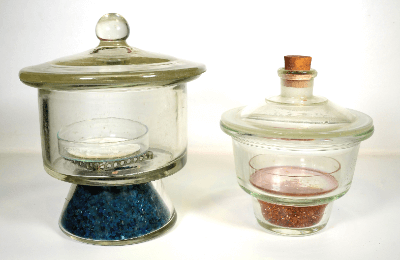
Desiccators

A desiccator (dehumidifier) is a container used to store items that should be kept away from moisture. The oldest types are circular and made of thick-walled glass. A desiccant such as silica gel may be used to maintain a dry condition. The internal air composition and humidity can be controlled. Reagents, samples, electronic equipment, etc., with hygroscopic or deliquescent properties are stored in this type. Desiccators of various sizes and functions are available according to the nature and size of the sample or substance to be stored inside.

Purpose of use of desiccators

The main purposes of desiccators include the following:

1. Dehumidification and Dry Storage

Glassware, specimens and reagents, samples with tidal characteristics, plant seeds, electronic equipment, etc., are often stored in desiccators. Since desiccators are instruments for maintaining dryness, they are not suitable for wet materials. They should be dried beforehand before placing them in.

2. Storage of Optical Products

Camera lenses and semiconductor components can lose performance due to moisture and mold. For this reason, they may be placed in desiccators (auto-dry type) with powerful dehumidification functions.

3. Prevention of Material Oxidation

For more powerful dehumidification or to store items that need to be shielded from oxygen, it is necessary to control the air inside by gas displacement or vacuum.

Principle of Desiccators

Types of desiccators are classified according to the dehumidification method and can be roughly divided into the following categories:

1. Auto Dry Desiccator

These are equipped with a dehumidifier or similar device that controls humidity through electrical control. They can control the humidity inside the storage and require little maintenance.

2. Gas Displacement Desiccators

This method replaces the air inside the desiccator with an inert gas (nitrogen, argon, etc.) and has the highest dehumidification capacity. It is also capable of expelling moisture and oxygen inside the desiccator, making it suitable for storing samples that can react with oxygen.

3. Vacuum (Decompression) Desiccators

A vacuum desiccator removes air from the inside of a desiccator to create a vacuum. Vacuum desiccators are also used for vacuum drying, degassing, and defoaming (the process of removing gas from liquids).

4. Dehumidifier Type Desiccator

A desiccant agent such as silica gel adsorbs moisture in the chamber. The desiccant requires maintenance but is inexpensive and easy to obtain. Circular glass desiccators have grease applied to the contact points between the body and lid to make them airtight, so care must be taken to keep them dust-free. This type is also called a glass desiccator.

How to Use a Desiccator

This section describes how to use the dehumidifier type vacuum desiccator:

Vacuum desiccators have holes or other openings in the container for vacuuming. Also called glass desiccators, they are now also available in the same shape, made of polycarbonate or stainless steel. There are also products with vacuum gauges and small rectangular products.

Dehumidifier-type desiccators are supported firmly by the lid and body when carried. The mortise between the lid and body should be spread evenly with Vaseline or grease. Some polycarbonate decapitators are dry-sealed with an O-ring and do not require greasing. In this case, be careful to prevent dust from entering.

Place a desiccant in the lower part of the desiccator (under the middle plate). It is easier to replace the desiccant if it is placed in a container such as a crystal dish. In addition to silica gel, other desiccants include zeolite, potassium hydroxide, anhydrous calcium chloride, phosphorus pentoxide, and concentrated sulfuric acid. Silica gel and zeolite can be used repeatedly by regenerating them.

The reagent or sample to be dried is placed on the medium plate. In the case of a greased desiccator, the lid may stick and not open, so the lid should be placed 5 mm away from the body of the desiccator.

For vacuum drying, open the top cock and place a trap between the tubes in the middle of the tube. Suction is applied using an aspirator or similar device to reduce the pressure gradually. Close the cock after completely depressurizing the tube.

If the pressure has been reduced, open the cock to return the pressure to normal, and then open the lid. If air enters the desiccator with great force, the sample may be blown away, so place the filter paper against the glass tube where the air enters and open the cock. Once the filter paper falls out, the inside of the desiccator returns to normal pressure.

Open the lid by sliding it to the side. If too much force is applied, there is a possibility of dropping and breaking the lid. Be especially careful if the glass is made of glass.

Auto Dry Desiccator

Auto-dry desiccators are shaped like a typical storage cabinet or storage shelf.

They vary in size from small (40 cm x 35 cm x 45 cm) to large (nearly 180 cm high). The larger ones usually have casters for mobility.

Most auto-dry desiccators use a dehumidification method based on a solid polymer electrolyte membrane, which directly electrolyzes the moisture in the air inside the chamber and releases it outside the desiccators. Dehumidification capacity with this method can be up to ~25%, the humidity is adjustable, and no condensate is produced. More powerful dehumidification is also possible when used in combination with silica gel. UV-cut and anti-static products are also available.
カテゴリー
category_usa

Choke Coils

What Is a Choke Coil?

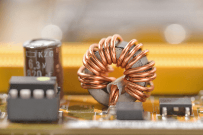
Choke CoilsA choke coil is an element used in electrical circuits and is a type of inductor optimized for use as a choke.
The meaning of choke in this case refers to the ability to keep AC currents above a certain frequency relatively high and to facilitate the passage of currents below that frequency, and is implemented in an electrical circuit.

The typical coil construction consists of a laminated plate of silicon copper or other steel plate as the core (iron core), around which conductors are wound in a spiral shape.

There are three types of choke coils: smoothing choke coils, active filter choke coils, noise filter choke coils, and power line choke coils. Each is used for different purposes.

Uses of Choke Coils

As mentioned above, there are four major types of choke coils depending on the application.

1. Smoothing Choke Coils

Choke coils are used to reduce the distortion of the current when AC current is converted to DC by a smoothing circuit or AC/DC converter, and to smooth the current. 

2. Choke Coil for Active Filter

Used as a high-frequency countermeasure in active filters used in analog signal input circuits such as measuring instruments

3. Choke Coil for Noise Filter

Choke coils are mounted in power supply circuits that are prone to noise inflow and used as noise countermeasures.

4. Choke Coil for Power Supply Line

Choke coils are used to match the load of RF power amplifiers and to reduce impedance resistance and losses in power supply lines.

Principle of Choke Coil

A choke coil consists of a core made of a laminated plate of silicon copper or other steel plate, around which conductors are wound in a spiral shape.

The choke coil is characterized by a higher inductance value than the coils used in general.

General coils and choke coils differ in the following characteristics:

  • General coil
    Easy to conduct direct current and difficult to conduct alternating current.
  • Choke Coil
    Easy to carry DC current and low frequency AC current, and hard to carry high frequency AC current. 

The reason why choke coils have the above characteristics is that they have a high inductance value and when an AC current of high frequency flows, an induced electromotive force is generated, which is opposite to the direction of the current flow, making it difficult for the current to flow.

When used as an active filter or for noise suppression, external noise that attempts to flow into a measurement device from its input terminal or power supply terminal of a power circuit has a high frequency. Choke Coils are often used in such applications because they can block high-frequency noise.

Other Information on Choke Coils

1. About Toroidal Coils

Choke Coils are often made by winding a conductor around a doughnut-shaped magnetic core, unless they are ultra-compact chip components, such as those used in smartphones. This is called a toroidal coil and can confine the magnetic flux in a closed loop (right-hand thread law). The advantage of toroidal coils is that they can achieve a larger inductance in a smaller size by utilizing this confined magnetic flux.

Important factors for inductor characteristics include Q-value and maximum allowable current. Based on the recent demand for compact, high-density packaging, manufacturers are competing to improve these inductor characteristics while reducing the size of the inductors.

2. Material of Magnetic Core

Various materials are used for the magnetic core of a choke coil, including laminated steel plates. One of the most commonly used magnetic core materials is ferrite material, which can be broadly classified into nickel-based and manganese based materials.

Nickel-based ferrite materials have very high insulation properties and are often used at high frequencies above 100 MHz.

Manganese-based ferrite materials are inexpensive and have high magnetic permeability and saturation flux density, and are often used in common mode chokes for low-frequency power lines.

カテゴリー
category_usa

Check Valves

What Is a Check Valve?

A Check Valve is a valve that controls the flow of fluid in a pipe in one direction only and prevents flow in the opposite direction.

Synonyms include Non-Return Valve, One-way Valve, Reflux Valve, Pressure Retention Valve, and Back-Flow Prevention Valve.

Uses of Check Valve

A Check Valve is used when you do not want fluid to flow backward.

The basic uses of Check Valves are as follows:

  • Prevention of mixing of two fluids
  • Preventing backflow
  • Controlling flow direction
  • Preventing water hammer

When installed at a point where two fluids merge, the check valve prevents the mixing of the two fluids and controls the flow of only one of them.

When installed in a rising piping section on the discharge side of a pump, fluid flows while the pump is running, and after the pump is stopped, the Check Valve closes to prevent fluid in the piping at a higher level downstream of the pump from flowing back to the pump.

In steam piping, it is also used to prevent water hammer. Water hammer is a phenomenon in which the pressure in a piping temporarily rises and falls due to a sudden change in fluid velocity. The pressure fluctuations caused by water hammer can damage pumps and piping, and Check Valves are used as a preventive measure.

Principle of Check Valve

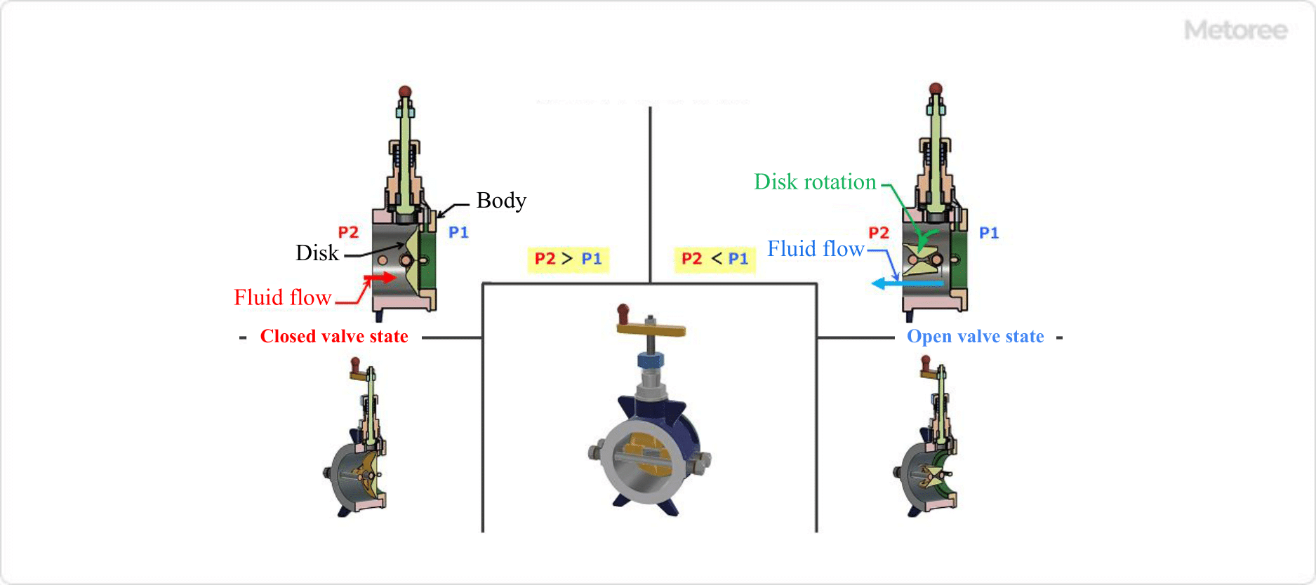
In a Check Valve, the valve disc is actuated to open and close by the pressure difference between the inlet side (primary side P1) and the outlet side (secondary side P2) of the fluid.

The pressure difference and valve operation are as follows:

Open: Inlet side (primary side P1) pressure is higher than outlet side (secondary side P2) P1 > P2
Closed: Inlet side (primary side P1) pressure is lower than outlet side (secondary side P2) P1 < P2

When the pressure at the outlet side (secondary side P2) is higher, the disc is pressed against the seat surface by back pressure and adheres tightly to prevent fluid backflow. The disc automatically opens and closes according to this pressure difference, and the fluid flows or does not flow.

Types of Check Valves

There are five types of Check Valves. The features of each are as follows:

1. Swing Check Valve

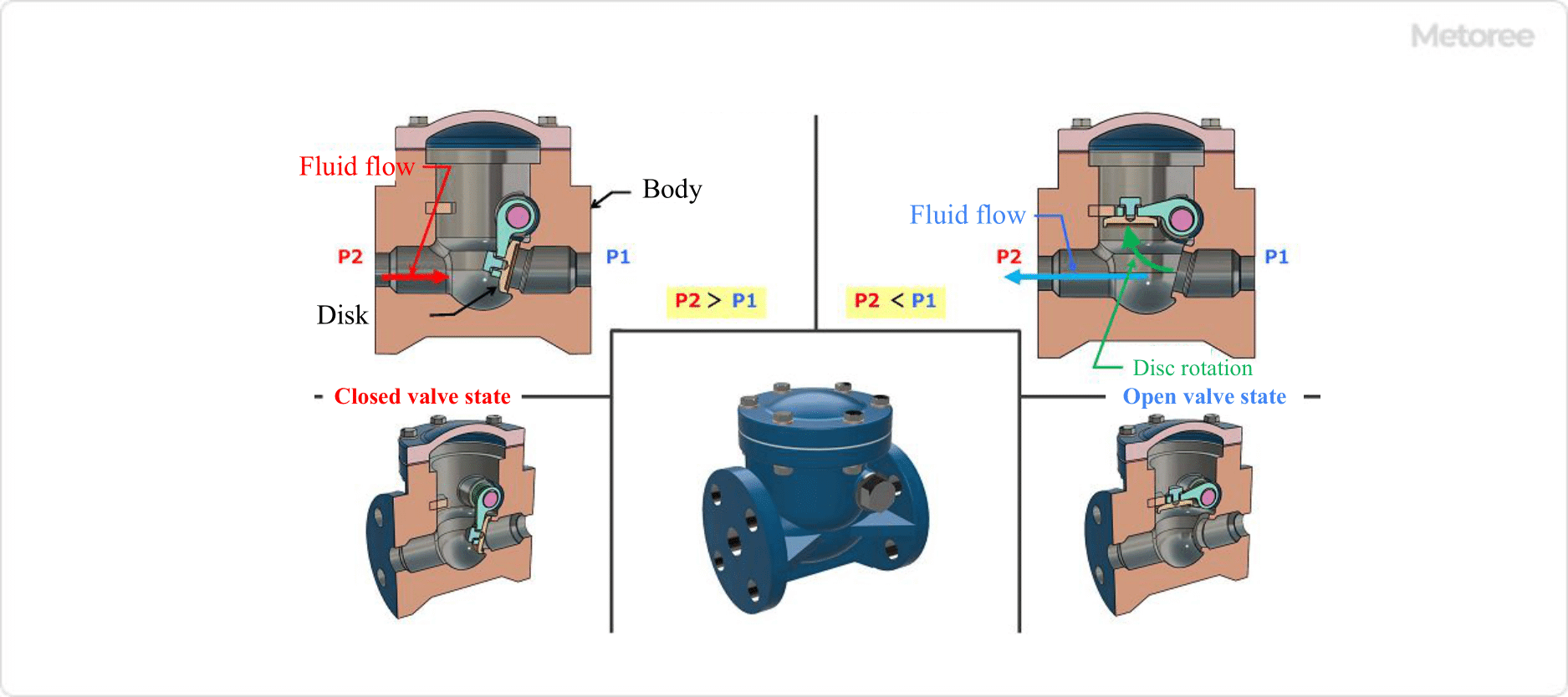
Swing check valves have a straight fluid flow and are mounted directly on an arm or disc with the disc attached to a hinge mechanism. The disc rotates with the hinge as a fulcrum and opens or closes the valve according to the pressure difference of the fluid.

Figure 1. Swing check valve

Figure 1. Swing check valve

Features

  • Generally, when the disc is fully opened at the full port, the disc does not block the flow path and the pressure loss is small.
  • Full port means that the flow path of the valve body is the same diameter or larger than the inside diameter of the piping.
  • When the disc weight is heavy, the minimum pressure differential for valve opening and the cracking pressure will be large. For lighter discs, the minimum pressure difference to open the valve and the cracking pressure will be smaller.
  • Cracking pressure is the pressure difference for a given flow rate.
  • Since the disc rotates on a hinge shaft, the shaft and bearing side will wear out due to long-term use and frequent operation. This can result in poor opening and closing action of the disc and reduced sealing between the disc and the seat.
  • Since the disc rotates at a relatively large angle from fully closed to fully open, its response to sudden pressure changes is low. Heavy discs also have the problem of greater impact on the seat during abrupt valve closure.

Installation

When the piping is horizontal, or when the piping is vertical, it is used when the fluid flows from downward to upward. It cannot be used when the fluid flows from upward to downward.

2. Lift Check Valve

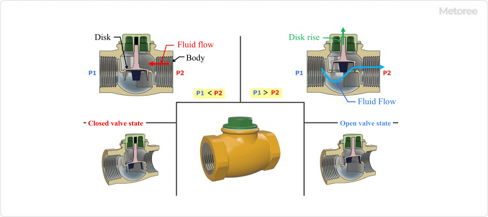
The lift check valve is a mechanism in which the fluid flow is S-shaped and the disc to which the shaft is attached rises and falls. The disc rises or descends depending on the pressure difference, and opens or closes the valve.

Figure 2. Lift check valve

Figure 2. Lift check valve

Features

  • The flow path is S-shaped and pressure loss is high.
  • Due to the heavy weight of the disc, the minimum pressure differential for valve opening and the cracking pressure are large.

Installation
Limited to grounding only when piping is horizontal. Cannot be used when piping is vertical and fluid flows vertically.

3. Wafer Check Valve

Wafer check valves are wafer-shaped valves that are installed by sandwiching the valve body between flanges and tightening bolts and nuts. The fluid flow is nearly linear and incorporates two semi-circular discs with a hinge mechanism.

The two discs rotate to open the valve due to the difference in fluid pressure using the hinge as a fulcrum, and rotate in the opposite direction to close the valve due to the coil spring attached to the discs.

Figure 3. Wafer check valve

Figure 3. Wafer check valve

Features

  • The flow path is almost straight and the pressure loss is small.
  • Wafer-shaped body is thin and lightweight.
  • Can be directly attached to pumps and other equipment.
  • The disc is forced to rotate by a spring and immediately closes, thus reducing water hammer phenomenon.
  • It has high sealing performance with high hermeticity.
  • It may be somewhat less responsive and less durable to cavitation and unbalanced fluid flow.
  • Some have a built-in bypass channel, eliminating the need to drain residual fluid or install bypass piping for priming.

Installation
Piping can be used in a variety of orientations, including horizontal, vertical, and inclined. When the piping is vertical, the fluid can be used in either vertical or horizontal flow direction.

4. Ball Check Valve

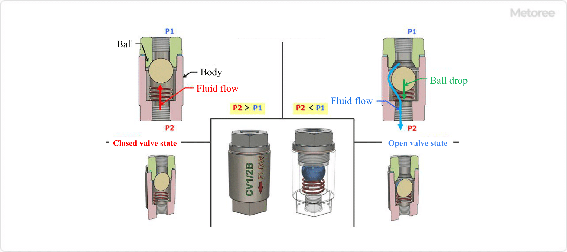
The ball check valve is a mechanism in which the fluid flow is S-shaped and the ball of the valve plug rises and falls. The ball rises and falls depending on the pressure difference to open or close the valve.

Figure 4. Ball check valve

Figure 4. Ball check valve

Features

  • The flow path is S-shaped or straight, and pressure loss is not so large.
  • Since the disc motion is unrestrained, some foreign matter in the fluid is tolerated.
  • Not effective in preventing water hammer.

Installation
Piping is available for horizontal and vertical applications. The vertical version opens and closes under the ball’s own weight, so it cannot be used when fluid flows from below to above. 

5. Spring Disk Check Valve

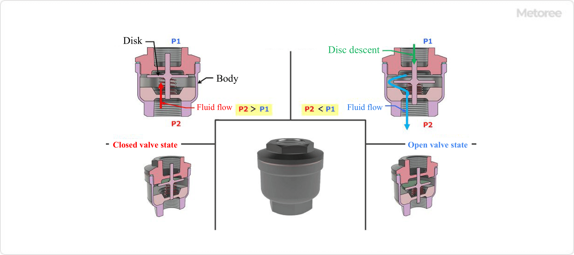
The spring disc check valve is a mechanism in which the fluid flow goes around the disc in an S-shape and the disc to which the shaft is attached rises and falls. The disc rises due to the pressure difference and descends by spring force to open or close the valve.

Figure 5. Spring disk check valve

Figure 5. Spring disk check valve

Features

  • The flow path is S-shaped and flows around the disc, resulting in a large pressure drop.
  • The disc is lightweight, and the minimum pressure differential for valve opening and the cracking pressure are small.
  • The operating distance between fully open and fully closed is small, resulting in excellent responsiveness.

Installation
Piping can be used in either horizontal or vertical direction. When the piping is vertical, the fluid can be used in either vertical or horizontal flow direction.

カテゴリー
category_usa

PH Meters

What Is a pH Meter?

pH Meters

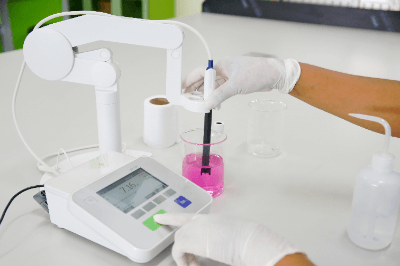
A pH meter is a precise instrument used to measure the pH, or hydrogen ion concentration, of a liquid, which is an essential indicator of water quality. These devices are vital in various fields, including environmental monitoring, food production, and medical research.

Uses of pH Meters

pH meters play a critical role in industries where water quality is paramount, such as waste management at incineration plants, boiler maintenance at thermal power plants, and wastewater management in construction. In the food industry, pH levels directly impact the taste and safety of products, necessitating accurate pH measurement.

Principle of pH Meters

The glass electrode method, commonly used in pH meters, involves measuring the potential difference between a glass electrode and a reference electrode. This potential difference, which changes with pH, allows for precise determination of a liquid’s pH level.

Electrode of pH Meters

Modern pH meters typically combine a glass electrode and a temperature sensor for accurate readings. The glass electrode, which has largely replaced platinum/hydrogen electrodes, contains an internal buffer solution sensitive to pH changes. This setup allows for a wide range of solution measurements.

Recent advancements have led to the development of composite electrodes, which integrate measuring and reference electrodes, simplifying the measurement process and enhancing the device’s versatility.

Measuring Soil With a pH Meter

Soil pH measurement is crucial in agriculture to ensure optimal growth conditions for various crops. However, measuring soil pH requires different techniques compared to liquid measurement. The MAFF provides guidelines for a simple indicator method, and portable pH meters are also available for direct soil testing.

カテゴリー
category_usa

Ducts

What Is a Duct?

Ducts

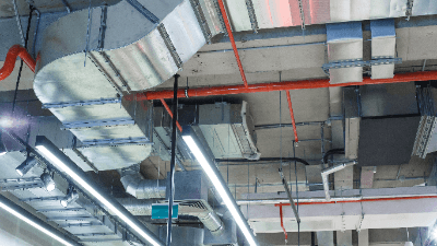
A duct is an air conditioning system and refers to an air passageway. They are used for ventilation, air conditioning, and smoke exhausts in buildings, as well as for large machines to exhaust internal heat and impurities.

There are various types of ducts, and their sizes and materials vary depending on the installation location and intended use.

Use of Ducts

Ducts are used for the ventilation and air conditioning of buildings.

By using a blower or other device to create a flow inside the building and then ventilating it outside through ducts, fresh air, and temperatures can always be maintained inside the building.

There are two types of ducts: square ducts and round ducts. The uses of each are explained below.

1. Square Duct

Square ducts are used in straight and curved sections and are considered to have higher exhaust performance than round ducts. Therefore, they are used in kitchens, where a lot of exhaust air is required.

2. Round Duct

Round ducts are stronger and are used in places where durability is required, such as housing complexes and offices.

Principle of Ducts

First, let us start by explaining the difference between “ducts” and “piping. The biggest difference between “ducts” and “pipes” is that “ducts” allow only airflow, while “pipes” allow not only air but also water, various gases, and other fluids to pass through. Another difference is that “piping” tends to be a large-scale operation, whereas “ducting” is a simple operation.

The following is a list of the four main materials used for ducts.

  1. Galvanized: the most used material. It is used for air conditioning and exhaust air.
  2. Stainless steel: stainless steel has excellent corrosion resistance. Used in rust-prone areas such as food factories and air conditioning units.
  3. Galvanized steel: synthetic plating of aluminum and zinc. It has excellent corrosion and heat resistance and is less expensive than stainless steel. 4.
  4. PVC-coated steel: resin-coated zinc plating. It is mainly used in pharmaceutical plants because of its superior resistance to alkalis and chemicals.

Care must be taken when installing ducts, especially regarding bends and slopes. Bends should be minimized as much as possible, extreme bends should be avoided. The length should be as short as possible because bends cause turbulence and resistance to airflow. In addition, ducts should be sloped because condensation can cause water to accumulate in the ducts. Ducts also make noise due to vibration, etc., so it is necessary to use reinforcement materials to prevent noise.

Outlet and Inlet of Ducts

There are various shapes of duct outlet/intake ports.

In office buildings and department stores, ceiling-mounted air outlets called “amonestats” are the standard, and they are available in round or square shapes. Amonestats have a cross-sectional structure with multiple overlapping wings, and the air that is blown out radiates, spreading the air throughout the room.

A “garage” is widely used at the intake port for taking in outside air. To prevent rainwater from entering outdoor use, the structure is fitted with drainage and water-return wings. Since they are used outdoors, weather-resistant and durable materials such as stainless steel are used. In addition, measures must be taken to install stainless steel netting to prevent insects and birds from entering.

In addition, various other types of blowing and intake ports are used according to the purpose. This includes the nozzle type to deliver air widely in large spaces such as gymnasiums and the universal type with movable wings attached.

Cautions for Duct Installation

Duct installation also requires attention to the following four points.

1. Loss Resistance of Ducts

Loss resistance in ducts obstructs the internal airflow and increases the air-blowing power, resulting in wasted energy.

The first step is to make the duct length as short as possible. In addition, supply and exhaust ports, branches, and bends create large loss resistance, so these should be minimized as much as possible. Nevertheless, unreasonable duct connections create significant loss resistance. Therefore, it is important to avoid forced connections while minimizing distances and bends and branches as much as possible.

2. Condensation in Ducts

Condensation may occur in ducts in some cases. Condensation in ducts can lead not only to corrosion of the ducts but also to electrical leakage and fire due to water entering a crisis through the ducts. To prevent this, a slope may be provided to drain the water in the ducts to the outside.

3. Vibration and Noise of Ducts

If ducts are installed incorrectly, vibration from blowers and other motors can be transmitted to the ducts, causing vibration and noise, so these measures are necessary.

One of the countermeasures is to install “deflection joints” to prevent equipment vibration from being transmitted to the ducts. In addition, by using “flexible ducts” with a bellows structure at the connection, not only can vibration be suppressed, but they can be used in locations where installation is difficult because they can be flexibly bent. Noise reduction can also be achieved by installing a sound-deadening box. The sound deadening box is filled with rock wool or glass wool inside to provide sound absorption and muffling functions.

カテゴリー
category_usa

PCR Tubes

What Is PCR Tube?

PCR Tubes

PCR Tubes are plastic tubes made specifically for use in PCR experiments. Polypropylene is usually used as the material, and a wide variety of sizes, shapes, and colors are available.

Uses of PCR Tubes

2206_PCR-Tubes_PCRチューブ-1.png

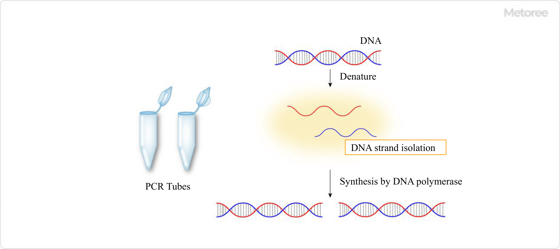
Figure 1. PCR tube and principle of PCR

PCR is an acronym for polymerase chain reaction, a technique that uses DNA polymerase to amplify a target DNA sequence from one to several million copies in a short period of time. Specifically, the series of reactions 1-3 below are called “cycles,” and by repeating 25-35 cycles, copies of the target DNA are synthesized exponentially.

  1. Denaturation: The double-stranded DNA template is heated to separate the DNA strands
  2. Annealing: short DNA molecules called primers are attached to adjacent regions of the target DNA
  3. Elongation: DNA polymerase synthesizes complementary strands of the template in the 3′-end direction starting from each primer

The device used to automatically control the temperature cycle and incubation time in PCR is a thermal cycler; PCR Tubes are manufactured for use in a thermal cycler. In order to select the correct PCR Tube, it is necessary to correctly understand the specifications of the thermal cycler you will be using.

In addition, since there are various types of PCR such as standard PCR, gradient PCR, real-time PCR, and qPCR, it is necessary to select the appropriate PCR for your purpose. At the same time, it is also important to properly prepare the experimental apparatus and reagents according to the type of experiment.

Structure of PCR Tube

2206_PCR-Tubes_PCRチューブ-2.png

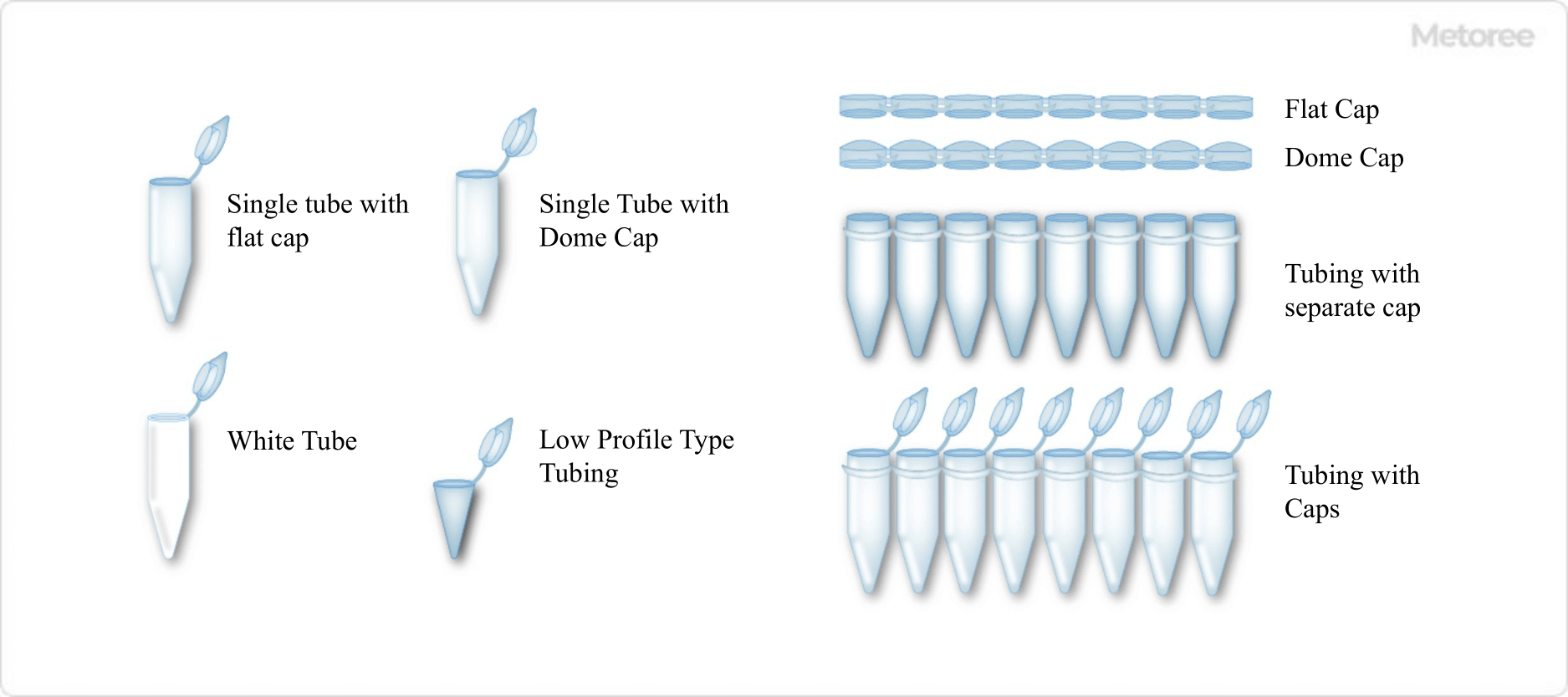
Figure 2. Various PCR tubes (Single tube) / Figure 3. Example of 8-row PCR tube

Polypropylene is usually used as the material. Polypropylene is chemically inert and can withstand rapid temperature changes during thermal cycling. In addition, the tube walls are manufactured to be thin and uniform to enhance heat transfer from the thermal cycler.

In addition, they are manufactured with the utmost care to ensure that they are free of dust and impurities such as endonucleases, pyrogens, DNA, lubricants, dyes, heavy metals, and fillers. This is because if the product becomes contaminated during manufacturing, dust particles can remain and interfere with PCR, or DNA fragments can serve as templates for nonspecific amplification, resulting in reduced experimental accuracy.

The structure consists of a tube portion that holds the sample and a cap portion, and is available in a single type with one separate tube, or an 8- or 12-tube type with multiple tubes.

There are two types of cap shapes: flat and domed, one with one cap per tube, and one with multiple caps in a row, which are separate from the tube.

There are two types of tube sections, one with a normal height (standard profile) and the other with a lower height (low profile). In addition to the transparent clear type, white ones are also available.

How to Select PCR Tubes

It is important to choose according to the type of experiment and to use the appropriate one for the thermal cycler you are using. For example, clear tubes (transparent type) make it easy to check the contents, while white tubes increase the sensitivity of qPCR by preventing fluorescence from refracting and diffusing outside the tube.

Domed caps allow rapid heat transfer from the thermal cycler, while flat caps can be marked with a marker and are easier to puncture with a needle during sample collection.

Low-profile tubes with a lower height minimize the space area in the reaction vessel, thus reducing the effects of evaporation and increasing the thermal conductivity compared to normal ones. Low-profile tubes are sometimes referred to as fast tubes because they are compatible with fast thermal blocks.

PCR Tubes are suitable for small- to medium-scale PCR experiments, and when the scale is larger, PCR plates are appropriate.

カテゴリー
category_usa

Casting Dies

What Is Die Casting Die?

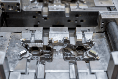
Casting DiesDie casting is a type of casting method in which molten material is heated and poured into a mold.

The materials to be melted are metals such as aluminum, zinc, and magnesium. The manufacturing process is automated and suitable for mass production. An advantage is low cost, since once a die is made, it can be used continuously.

The term “Casting Die” refers not only to the manufacturing method but also to the product itself made by this method. Compared to other casting methods, die casting has a shorter history since the method was established, and new methods are being created even today.

Uses of Casting Die

1. Automotive Parts

Die casting is used in a wide variety of automotive parts, including parts of the body, covers around water pumps, engines, transmissions, compressors for air conditioners, and other parts with complex shapes.

Recently, with the need for electrification and weight reduction, they are also used in parts around power steering and covers for control units. Aluminum die casting is often used for automotive parts because they are often complex and require good heat dissipation; although there are alternatives using ABS and other resins, aluminum die casting is still an essential part of automotive parts today.

2. Home Appliances

Casting Die products are also used in familiar home appliances such as TVs, air conditioners, washing machines, and electric cookers.

Like automotive parts, many home appliances are precision products, and mass production is required. Therefore, Casting Die is used because of its ability to handle complex shapes and to keep production costs low.

3. Other Products

Casting Die products also contribute to miniaturization and weight reduction. Therefore, they are often used for products that require lightness, such as golf equipment, cameras, fishing equipment, OA equipment, and cell phones.

Principle of Die Casting Die

There are several types of Casting Die. The general construction method is the following procedure:

  1. The fixed and movable molds of the Casting Die are pressed together with great force.
  2. Molten metal is injected into the space between them at a high pressure of several tens of megapascals.
  3. When the hot water hardens, the movable mold is moved to remove the part.

Special methods are as follows:

1. Vacuum Casting Die Method

After the molds are pressed together, air is removed to create a vacuum. After the vacuum is created, hot water is injected and the product is removed. Since air is removed, oxides are suppressed and high quality products can be produced. 

2. Non-Porous Casting Die Method

After the molds are pressed together, the inside of the mold is filled with oxygen. After filling, hot water is injected and the product is removed. This method has the feature of preventing the generation of nests due to the decompression caused by the oxidation reaction. This method is suitable for products that require strength. 

3. Local Pressure Casting Die

After the molds are aligned, hot water is injected. When the hot water is half solidified, the mold is partially re-pressurized. By re-pressurizing, hot water can be replenished to the area where shrinkage has occurred during solidification, thus making it possible to produce products with fewer cracks.

Other Information on Casting Die

1. The Difference Between Casting Die and Casting

Casting is a method of forming products by pouring liquid metal melted in a high-temperature furnace into molds made of sand, metal, or wax. Basically, no external force is applied, but the liquid metal’s own weight and subsequent flow is used.

Casting Die, on the other hand, is a further development of casting, in which liquid metal is injected into a mold under pressure to form it.

In casting, the high-temperature liquid metal is not so fluid that it takes time to spread to every corner of the mold under its own weight alone. Furthermore, it shrinks as it solidifies, so dimensional changes and wrinkles created during flow are likely to cause defects.

On the other hand, in Casting Die, pressure is applied to the liquid metal and injected into the mold, so the metal is quickly spread to all corners of the mold. Because it is formed under pressure, it has high dimensional accuracy and excellent surface roughness. This allows for high productivity in mass production.

Another major difference from casting is that finishing and inspection processes can be reduced due to the high quality.

2. Disadvantages of Casting Die

Undercut shapes are disadvantageous
Casting Die is used to extrude the product after molding, and it is difficult to extrude horizontal holes or flange parts that are perpendicular to the direction of extrusion. Such parts are called undercut shapes. To make products with undercuts, we use cores that can be removed after casting. This makes the mold more complex and increases the manufacturing cost.

Lower strength than cast products
In Casting Die, high-temperature liquid metal is forced into the product at high speed and high pressure, causing air that cannot escape and evaporated gases from the mold release agent that separates the mold from the product to be entrained in the product. This inevitably results in the inclusion of internal defects and a reduction in strength.

When plastic forming is applied by external force, such as hot forging or cold forging, it is possible to crush these defects, and thus the strength of the product is superior to that of Casting Die. Recently, however, Casting Die methods have been developed that solve this problem.

High initial cost
The disadvantage of Casting Die is that the initial cost is high because of the complicated mold shape and the need to use expensive materials with excellent resistance to heat and aluminum corrosion. In addition, since the die is repeatedly subjected to high temperature and high pressure loads hundreds or thousands of times a day, it does not have a long service life, resulting in high running costs.

カテゴリー
category_usa

Solar Generators

What Is a Solar Generator?

Solar GeneratorsA Solar Generator is a device that supplies electricity generated by solar panels.
Generally speaking, a solar generator is a product that combines a portable accumulator, solar panels, and a power conditioner.

As an emergency power source, demand for this product has been improving in recent years.

Uses of Solar Generators

Solar Generators are used for camping and disaster situations. The solar panels generate electricity during the day while the stored power is used at night. Since they do not require a power grid, they are especially useful in emergencies.

Solar Generators can be broadly classified into two types: fixed and portable.

Examples of use are shown below.

  • Emergency power source in the event of a natural disaster
  • Independent power source for off-grid power generation
  • Power supply for overnight stay in a car or camping

Principle of Solar Generator

A Solar Generator consists of a solar panel, a power accumulator, and a power conditioner. The solar panels convert sunlight into electricity, the converted electricity is stored in the accumulator, and then converted to a voltage that is easy to use with the power conditioner.

Solar panels are classified into two types: Silicon-Based and Compound-Based.

For Solar Generators, Amorphous Silicon and Polycrystalline Silicon solar panels are used.

1. Amorphous Silicon

Amorphous silicon is manufactured by placing a thin layer of amorphous silicon on a substrate such as glass. While its conversion efficiency is low, it is characterized by its light weight, productivity and versatility.

Compared to monocrystalline silicon and polycrystalline silicon, power generation conversion efficiency does not decline even at high temperatures.

2. Polycrystalline Silicon

Polycrystalline silicon is a low-cost version of solar panels made from silicon scraps generated during the production of monocrystalline silicon. While they generate less power than monocrystalline silicon, they can be manufactured at a lower cost.

Storage Battery for Solar Generator

Not only solar power generation, but also electric energy cannot be stored. Electricity transmitted from power companies is only generated in the required amount at that moment. The power company plans power generation while forecasting demand.

In Solar Generators, electricity is stored as chemical energy by means of storage batteries. Therefore, power is available even during power outages caused by natural disasters such as earthquakes and typhoons.

However, storage batteries are expensive, so the storage batteries in Solar Generators also account for a large proportion of their price. They also require temperature control, as their lifespan is affected by temperature. Solar Generators use lead-acid batteries or lithium-ion batteries.

The characteristics of each are described below.

1. Lead-Acid Batteries

Lead electrode plates are inserted into dilute sulfuric acid, the electrolyte. Lead dioxide is used for the positive electrode (anode) and lead for the negative electrode (cathode), and electricity is generated through a chemical reaction between the dilute sulfuric acid and the lead. In addition to Solar Generators, lead-acid batteries are also used in car batteries and uninterruptible power supplies.

Lead-acid batteries can be manufactured inexpensively, but they have the disadvantage of being heavy. They can be repeatedly charged and discharged, but their performance deteriorates when over-discharged.

2. Lithium-Ion Batteries

A lithium-ion battery uses lithium transition metal oxide such as lithium cobaltate for the positive electrode, carbon materials such as graphite or graphite for the negative electrode, and organic solvents for the electrolyte. It charges and discharges when lithium ions move between the positive and negative electrodes.

In addition to Solar Generators, they are also used in smartphone batteries. While lithium-ion batteries are compact, lightweight, and resistant to deterioration, they are vulnerable to temperature changes and expensive.

Other types of batteries include nickel-metal hydride batteries and NAS storage batteries.

カテゴリー
category_usa

Zeolites

What Is Zeolite?

Zeolites

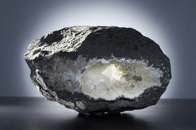
Zeolite is a crystalline aluminosilicate. Its main components are silicon, aluminum, and oxygen, forming a porous crystal structure. The smallest basic unit of zeolite is the SiO4 tetrahedron, which is assembled into a three-dimensional structure. Some of the silicon is replaced by aluminum, and cations exist around it to regulate the charge.

In general, zeolites have ion exchange and adsorption capacities that derive from their unique crystal structure. This property is applied to gas adsorption, cation exchange, and catalysis.

Zeolite Application

Zeolites have a myriad of pores at the molecular level and depending on their structure, they possess various properties such as adsorption, ion exchange, and catalytic properties.

Zeolites are also called molecular sieves and can sieve molecules according to pore size. This property is used to remove water and impurities from gases and solvents. Zeolites are also used as soil conditioners, water treatment agents, carbon dioxide and nitrogen adsorbents, and are catalysts for petrochemical products.

Zeolite Principles

Zeolite is a porous crystalline aluminosilicate composed of SiO4 and AlO4 tetrahedra. Zeolites are composed of SiO4 tetrahedra and AlO4 tetrahedra.

Zeolites are composed of SiO4 and AlO4 tetrahedra in a wide variety of crystal structures, and currently, more than 240 different structures have been found. Each of these differs greatly in pore size and adsorption capacity.

Zeolites are classified into three main types: natural zeolite, synthetic zeolite, and artificial zeolite. There are many types of natural zeolites, including borite, mordenite, and clinoptilolite. Most of them do not have a uniform crystal structure and occur together with quartz and carbonates. Synthetic zeolites are artificially synthesized zeolites. Synthetic zeolites have higher adsorption and ion exchange capacities than natural zeolites, but the cost of synthesis is higher. Artificial zeolite is a zeolite synthesized without the high cost of synthetic zeolite. It can be synthesized by reacting coal ash with caustic soda. By changing the formulation and conditions, artificial zeolite with high functionality can be synthesized.

Water Treatment with Zeolite

Zeolite has been used as a material for the separation of membranes. Zeolite can be processed into inorganic membranes called reverse osmosis membranes to dehydrate organic solvents, remove water vapor from gases, and remove salt from seawater. For example, in the dehydration of organic solvents, water is removed by taking advantage of the slight difference in molecular weight between organic solvent molecules and water molecules. Hydrophilic organic solvents such as ethanol, isopropyl alcohol, butanol, ethyl acetate, and acetone can also be dehydrated.

There are three advantages to using zeolites for water treatment.

The first is that zeolites have uniform pores, enabling separation by molecular sieving with high precision. Zeolites are called molecular sieves because they have numerous pores at the molecular level and can sieve at the molecular level.

Second, because of its heat resistance and chemical resistance, zeolite can be used under high-temperature conditions and applied to various substances. It can be used for chemicals that are harmful to the human body, such as those used in chemical plants and paint factories.

Third, zeolite itself is available in a wide variety of types, each with various compositions and pore sizes. This allows for a much greater degree of freedom in the treatment process, as materials can be selected according to the object to be treated and the application.

As the composition of the zeolite changes, the properties of the water treatment also change. For example, zeolite contains a large amount of silicon (Si) and aluminum (Al). When the Si/Al ratio is low, the zeolite becomes more hydrophilic and shows high water adsorption properties, making it suitable for the dehydration of solvents. Conversely, when the Si/Al ratio is increased, hydrophobicity increases and chemical resistance to acids and other substances is high, making zeolite suitable for treating highly acidic chemicals.

Environmental conservation with zeolite

Zeolites are attracting attention for their use in agriculture and environmental conservation due to their adsorption and ion exchange capacities.

Zeolites can be applied to ponds, swamps, and soil to adsorb heavy metals and eutrophication-causing components, thereby protecting the water and soil environment. Zeolite is also an excellent material for the deodorization and decomposition of toxic components of automobile exhaust gas to maintain normal air, water, and soil environments.

Additionally, zeolites are used in agricultural and horticultural applications. Zeolite has regular pores that allow for adequate aeration. Mixing soil with zeolite creates soil that provides sufficient oxygen to the roots and improves plant growth. It can also adsorb a variety of substances, allowing it to retain some of the fertilizer components while supplying an adequate amount to the plants. It can also purify the soil by adsorbing impurities contained in the soil. Minerals dissolved in zeolite can also have the effect of being used as plant nutrients. Examples of applications in the horticultural field include potted plants, vases, and hydroponics.

Energy and petrochemical applications

Zeolite is one of the indispensable catalytic materials in the petrochemical field. Zeolites are used for isomerization, cracking, and aromatization of hydrocarbons, and to produce fuel oils such as gasoline from methanol. Fluidized bed catalytic cracking (FCC) is one of the most typical examples. This is a reaction that breaks down the components obtained from the upstream of crude oil into molecules with lower carbon numbers. A method used to produce higher value-added components such as gasoline and is indispensable to our current way of life.

In recent years, zeolite separation membranes have also been developed to remove carbon dioxide from biogas, natural gas, and coal gasification combined cycle power generation, etc. These are attracting attention as energy sources with less environmental impact, and zeolites are also very important in the energy and environmental fields.

Ceramic Bearings

What Is a Ceramic Bearing?

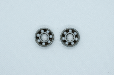
Ceramic BearingsA Ceramic Bearing is a bearing that uses ceramic as its material. Ceramic bearings are lighter than metal bearings because they are made of ceramic.

Ceramic bearings are also more resistant to corrosion and wear than metal bearings. Ceramic bearings are therefore used in corrosive environments and electromagnetic atmospheres.

Uses of Ceramic Bearings

Ceramic Bearings are widely used in consumer products. Typical examples are refrigerators, washing machines, and vacuum cleaners. Ceramic Bearings may be used in equipment that is in close proximity to food or the human body for hygienic reasons.

In industrial applications, ceramic bearings are used in clean rooms, vacuum environments, high-temperature environments, and underwater. Due to their high resistance to high temperatures and wear, they are suitable for equipment in the above environments.

Examples of industrial applications are as follows:

  • Food and chemical manufacturing equipment
  • Bearings in generators and turbines
  • Liquid fuel transfer pumps
  • Semiconductor manufacturing equipment and space industry equipment
  • Inspection equipment and machine tools

Principle of Ceramic Bearings

Ceramics are inorganic compounds synthesized by combining metallic and non-metallic elements. The combination of metal and non-metal elements make it lightweight and resistant to corrosion and high temperatures. It also has high hardness and wear resistance.

Ceramic Bearings can be used in harsh environments because the material is ceramic. Because the characteristics vary depending on the type and ratio of the elements combined, a variety of Ceramic Bearings are available for different purposes of use.

Other special material bearings include resin bearings, stainless steel bearings, and urethane bearings. Each is used according to the application.

Other Information on Ceramic Bearings

1. Ceramic Bearing Life

Ceramic Bearings are generally made of silicon nitride, which has a higher rigidity than high-carbon chromium bearing steel, the material used in metal bearings. This results in higher contact stress, and the difference in rigidity due to material does not simply translate into a difference in life.

Although the load rating of Ceramic Bearings is specified to be equivalent to that of metal bearings, life tests have confirmed that the life of Ceramic Bearing is equal to or greater than that of metal bearings. Therefore, the life tends to be longer than the calculated value.

Flaking due to fatigue occurs in bearings that have reached their life expectancy, just as it does in metal bearings.

In addition, silicon nitride has about half the mass of high-carbon chromium bearing steel. As a result, centrifugal force during rotation is small, heat generation is small, and thermal deformation is virtually nonexistent. When rotating at high speeds under high temperatures, it exhibits superior characteristics to metal bearings.

2. Accuracy of Ceramic Bearing

The accuracy of Ceramic Bearing is also determined by the accuracy grade of the bearing. Technically, it is possible to produce ISO Grade 3 or higher, but it is more expensive; ISO-Grade 3 is ultra-high precision with a diameter of 12.7 mm or less, diameter variation, and sphericity of 0.08 μm or less. Therefore, they are used for special applications such as ultra-high-speed, high-precision spindles with rotational speeds of 100,000 RPM or higher.

In addition, Ceramic Bearings maintain their accuracy even under high temperatures because of less thermal expansion and thermal deformation compared to metal bearings. Therefore, they are suitable for use in high-temperature environments.

Although the rotational accuracy of a bearing requires the accuracy of the bearing itself, the housing and rotating shaft have a considerably greater effect. In addition to using high-precision bearings, the parts surrounding the bearing must also be machined to high precision. Since the accuracy also depends on the assembly, skilled assembly techniques are required for high-precision rotary components.