カテゴリー
category_usa

Slide Switch

What Is a Slide Switch?

Slide Switches
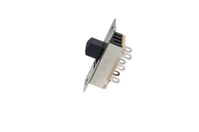
A slide switch is a switch that is turned on and off by sliding a knob.

There are vertical and horizontal slide switches, and they are also used in familiar electrical appliances. However, their use in digital products is decreasing. There are various terminal connection methods for slide switches, including through-holes, right angles, solder, and screws. In recent years, miniaturization has progressed, and some products are mounted as DIP switches.

Uses of Slide Switches

Slide switches are used in a wide range of applications, from industrial products to home appliances. The following are examples of slide switch applications.

  • Home appliances such as electric fans
  • Portable products such as shavers and hair dryers
  • Lighting fixtures such as flashlights
  • Industrial equipment settings such as inverters

Some of the low-profile products are as thin as 1.4 mm in thickness, and are becoming smaller and smaller. Compact slide switches are sometimes used as dip switches integrated into circuit boards. Some products have a self-cleaning effect by using an ingenious contact mechanism.

Principle of Slide Switches

A slide switch consists of terminals, a knob/casing, and contacts.

The terminal is the component that connects the external wiring. Pin-shaped or soldered terminals are used. Generally, copper alloys and other materials are used, but expensive contacts made of gold or silver may be used for low current loads.

The knob is a movable part that is operated by a person, and the casing is a part that supports and insulates other parts. Strong insulating materials are preferred, so hard synthetic resins are generally used. Below the knob is a movable slice of the contact point, which can be switched by switching the knob.

The contact point is a part that serves as a pathway for electricity and is composed of a movable and a fixed intercept. Products that make contact at two points are more reliable as switches than those that have a single point of contact between the movable and fixed interlocks. In addition, the clip-type sliding contact method can be expected to have a self-cleaning effect.

How to Select a Slide Switch

Slide switches are selected according to the number of circuits and terminals required. Specifically, selection should be made from the following perspectives:

1. Allowable Current and Allowable Voltage

Allowable current is the amount of current that a slide switch can energize. The larger the allowable current, the larger the current that can flow, but the smaller the size, the smaller the allowable current tends to be. Products ranging from several tens of A to several hundreds of mA are available, and generally products of 0.1 to 1A are common.

The allowable voltage (withstand voltage) is the amount of voltage that a product can withstand; products intended for use at 100 VAC are often labeled as having an allowable voltage of 125 VAC. For board mounting, the allowable voltage is often 30VDC.

2. Mounting Method

The mounting method is to install a slide switch. The mounting method is closely related to the terminal shape, and includes board surface mounting and board hole insertion. There are also various shapes, such as products with switches arranged vertically or horizontally to the mounting surface.

3. Functional Action

The functional operation of slide switches includes pole, throw, and contact type. These are often combined and expressed as “two-pole, double-throw” and so on.

The poles of a switch are the number of circuits that can be opened and closed by performing a single operation. It refers to how many contact points on an electrical circuit can be switched at the same time by sliding the switch. Many small products have one pole, and products with two to four poles are available.

The contact type refers to the type of contact that is activated by switching, such as a-contact or b-contact. Slide switches have normally open, and normally closed terminals and often use a c-contact with a single common terminal. The throw of a switch refers to the number of operations performed by the switch. Slide switches are generally of the twin-throw type, meaning that the throw of the switch has two contacts.

4. Switching Method

Switching method is the contact action when switching. Shorting and non-shorting products are available.

Shorting is a method in which two or more contacts conduct simultaneously when switching contacts, while non-shorting is a method in which the circuit is disconnected once at the moment of switching contacts. Generally, non-shorting products are more common.

カテゴリー
category_usa

DC Motor

What Is a DC Motor?

DC Motors

A DC motor is a motor that runs on a DC power source. It generally refers to brushed motors.

There are two types of electricity: DC and AC. DC power is a power source in which the direction of the current is always in one direction, while AC power is a power source in which the direction of the current is periodically switched. In English, DC stands for Direct Current, and AC is Alternate Current. They are called DC power supply and AC power supply, respectively. Therefore, a DC motor refers to a motor that uses a DC power supply.

Uses of DC Motors

DC motors are widely used for both industrial and general applications. For general use, they are used in radio-controlled toys and automobile models. DC motors are often used in toys because of their simple and inexpensive structure and because dry-cell batteries can power them.

In industrial applications, DC motors have been used in train running motors since the 1800s. In recent years, DC motors have been used in running motors for electric vehicles and motors for HDD rotation.

Principle of DC Motors

Inside DC motors, a rotor with a coil wound around it is installed in the center, and a stator polarized into N and S poles is installed around it.

When an electric current is applied to the DC motors, a magnetic field is generated in the coil according to Fleming’s law. When the magnetized rotor poles and stator poles are the same, a repulsive force is induced, and when they are opposite poles, an attractive force is induced, causing the rotor to rotate.

Reversing the current flowing through the rotor changes the attractive and repulsive forces, which are repeated alternately to rotate the rotor in a fixed direction. The power required for magnetization is provided by a conductor brush in contact with a part called the commutator.

Due to its simple structure, a motor with high output torque efficiency can be manufactured cheaply. However, because the commutator and brushes rotate in contact with each other, the brushes wear out. Therefore, for small brushed DC motors, brush life is motor life.

Types of DC Motors

Permanent magnet DC motors and electromagnet field DC motors are the two main types of DC motors, although brushless DC motors have also become available in recent years.

1. Permanent Magnet Type DC Motors

Permanent magnet DC motors use a permanent magnet in the stator. The rotor is an electromagnet consisting of an iron core and a coil. Since there is no need to energize the stator, the structure and control are simple. 

2. Electromagnet Field Type DC Motors

The stator and rotor are both electromagnets in the electromagnet field-type DC motors. Since the field flux increases as the current to the stator increases, these motors have been used in medium to large-sized DC motors.

3. Brushless DC Motors

Brushless DC motors use permanent magnets in the rotor. The displacement of the rotor is read by a magnetic sensor and controlled by changing the magnetic field generated by the stator. While brushless motors have a long service life and are easy to maintain due to the absence of brushes, they require the use of a power supply dedicated to brushless DC motors.

Other Information on DC Motors

1. Differences between DC Motors and AC Motors

The difference between DC motors and AC motors is the power source: DC motors are driven by a DC power source, while an AC power source drives AC motors. The features of each are listed below.

2. Features of DC Motors

  • Battery power can be used as it is
  • Stable rotational characteristics
  • It can be manufactured at a low cost
  • High torque control performance and stable response
  • Uneven rotation
  • Difficult to generate high DC voltage, making it difficult to produce larger motors

3. Features of AC Motors

  • The commercial power supply can be used as it is
  • No brushes, simple and robust structure
  • Easy to generate high voltage and can be enlarged in size
  • Rotation speed is constant according to power supply frequency
  • VVVF device is required to control rotation speed

The power supply provided by the power company is AC power. When driving DC motors from an AC power source, a rectifier (converter) is used to convert it into a DC power source.

カテゴリー
category_usa

AC Motor

What Is an AC Motor?

AC Motors

An AC motor is an electric motor that is driven by an AC power source.

AC stands for alternating current, which is a current with a frequency that switches between positive and negative over time. A power supply that outputs such a current is called an alternating current power supply (AC power supply).

AC motors are largely composed of a stator and a rotor.

  • Stator: A coil wound on an electromagnetic steel plate.
  • Rotor (rotor): A rotor core made of electromagnetic steel sheet with aluminum and coil windings to form a cage-like structure of conductors.

An electric motor driven by a direct current power source is called a direct current motor or DC motor (English: direct current motor).

Uses of AC Motors

AC motors are used to rotate equipment such as pumps in factories, conveyors, rollers, and fans. They are used by connecting the equipment (rollers, etc.) to be rotated, and the shaft of the rotor with a device called a coupling.

Compared to DC motors, which are driven by a DC power source, AC motors are widely used because they are easier to maintain and do not have brushes, which are consumable devices.

In recent years, AC motors have become more widely used because they allow speed control, which was once considered easier with DC motors.

Principle of AC Motors

399_AC-Motors_ACモーター-1.png

Figure 1. The principle of rotating magnetic field generation

In AC motors, a 3-phase AC power supply, out of phase by 120 degrees, is applied to the stator coil, and the current flowing through the coil causes the electromagnetic steel plate to become an electromagnet, forming a magnetic field in the motor (the right-hand thread’s law determines the polarity of the electromagnet. The polarity of the electromagnet is determined by the right-hand screw law.)

Since the AC power supply is shifted in phase with time, the position of the magnetic field rotates with time, and this is called a rotating magnetic field. As the magnetic field rotates, eddy currents are generated in the rotor, and the eddy currents and the magnetic field generate a rotating force that causes the rotor to rotate (Fleming’s left-hand rule determines the direction of rotation). This principle of rotation uses the principle of Arago’s disk.

The number of stator poles is called the number of poles and is expressed as 2-pole or 4-pole. The speed of the rotating magnetic field Ns is determined by the number of poles p and the frequency f of the power supply p. The speed N of the rotor has a lag, called slip s, relative to the rotating magnetic field, which can be obtained by the formula N = 120f (1 – s) / p. s)/p. The rotational torque of an electric motor is inversely proportional to the speed of the rotating magnetic field and is maximum when the motor starts.

Types of AC Motors


399_AC-Motors_ACモーター-2.png

Figure 2. Types of AC motors

AC motors are mainly classified as shown in Figure 2.

They are broadly divided into synchronous motors and induction motors, but can also be classified according to the type of AC power source.

  • Single-phase AC motors
    These motors are powered by 100 VAC, as distributed to households. Motors used in home appliances, such as washing machine motors, are classified in this category.
  • Three-phase AC motors
    This category includes motors for pumps and conveyors that run on a three-phase power supply, such as those used in factories. In Japan, AC200V is the mainstream.

AC motors can also be driven from DC power sources. In this case, an inverter that converts DC to 3-phase AC is used together.

1. Synchronous motor

A synchronous motor is a motor in which there is no slippage (synchronization) between the rotating magnetic field and the rotor, and whose rotational speed is determined by the number of poles in the motor and the frequency of the power supply.

Synchronous motors are classified into various types according to the construction of the rotor, but here we will discuss the permanent magnet type, which is relatively commonly used.

Permanent magnet-type synchronous motors have magnets in the rotor core and rotate when the magnetic field of the magnets synchronizes with the rotational magnetic field of the power supply.

Magnets fixed to the surface of the rotor core are called Surface Permanent Magnets (SPM), while those embedded in the rotor core are called Interior Permanent Magnet (IPM).

2. Induction motor

399_AC-Motors_ACモーター-3.png

Figure 3. Rotor structure of induction motor

Induction motors are also called induction motors or asynchronous motors.

Induction motors are characterized by a slightly slower rotor speed than synchronous motors (i.e., the rotation speed of the power supply is asynchronous with the rotation speed of the rotor).

Figure 3 shows the rotor structure of an induction motor. As shown in the figure, induction motors are generally composed of aluminum or other conductors in a cage shape.

The rotating magnetic field from the AC power source generates an induced current in the cage-shaped conductor based on the principle of electromagnetic induction, and Fleming’s law states that a force is generated by the action of the current and magnetic field. This force causes the AC motors to rotate and move the machine connected to the output shaft.

カテゴリー
category_usa

Vibrometer

What Is a Vibrometer?

Vibrometers

A vibrometer is a device that measures the magnitude of an object’s vibration. Vibration magnitude is generally expressed on three scales: displacement, velocity, and acceleration.

It is essential to select which parameter to measure depending on the type of vibration you wish to measure and the item you want to evaluate. When measuring acceleration, it is sometimes referred to as an accelerometer.

Uses of Vibrometers

Vibrometers are widely used in research and development, production, and environmental protection. In the field of research and development, for example, the vibration characteristics of parts are measured during the product development stage to prevent resonance, damage, and abnormal noise.

In the production field, for example, vibration measurement of engines is used as a method of product shipment inspection to determine whether the engine is acceptable or not. In addition, to prevent damage caused by transportation, vibration during the transport is reproduced by testing equipment to improve packaging.

For turbine generators, for example, we monitor vibration during operation to detect malfunctions at an early stage. In the field of the environment, vibration measurement is essential for solving pollution problems caused by vibrations from factories and construction work.

The effect of vibration on the human body is determined by measuring the vibration level, which represents the ratio of vibration to a reference acceleration. Vibration levels are defined in ISO and JIS and are used to determine the riding comfort of automobiles and railroad cars.

They are also used to measure earthquake vibration and issue warnings and earthquake vibration waveforms to evaluate buildings’ earthquake-resistant and vibration-isolated structures.

Principle of Vibrometers

Vibration detection in vibrometers uses what is called a pickup. Pickups include piezoelectric, electromagnetic, mechanical, optical, and electromagnetic types.

1. Piezoelectric Vibrometers

The force generated by vibration is converted into a voltage proportional to that force by the piezoelectric effect of the piezoelectric element. There are two piezoelectric vibrometers: the shear type, which measures the strain on the surface of the piezoelectric element, and the compression type, which has a simple structure with a weight on the piezoelectric element. They are compact and lightweight and can measure up to a high-frequency range. 

2. Electromagnetic Vibrometers

This type consists of a magnet and a coil and measures changes in the electrical current generated by electromagnetic induction depending on the positional relationship between the interest and the coil caused by vibration.

3. Mechanical Vibrometers

Using a MEMS (micro-electric mechanical system) semiconductor element, this vibrometer measures changes in electrostatic capacitance in response to the displacement of a variable electrode.

4. Other Vibrometers

Optical vibrometers measure displacement by irradiating a laser beam, and electromagnetic vibrometers measure relative displacement using a microwave Doppler laser. These methods do not require a pickup to be attached to the vibrating object and are suitable for measuring the vibration of small things, hot objects, and liquid surfaces.

Other Information on Vibrometers

1. How to use the Vibrometers

It is recommended that the pickup be firmly fixed with stud bolts or other means so that it is in close contact with the non-measuring object. If the mounting method is not firmly fixed, the pickup may become a filter, and accurate measurement will not be possible.

Fixing methods other than stud bolts include the use of adhesives and magnets. Frequency analysis is widely used to analyze vibration. It is a method to determine what frequencies and how much intensity each frequency contains in the measured waveform.

2. Unit of Vibration

The definition of mechanical vibration is defined by JIS as a temporal change in the magnitude of a quantity representing the motion or displacement of a mechanical system, alternating between a state greater than and less than a certain average or reference value. Vibration consists of three elements: amplitude, frequency, and phase. When measuring vibration, there are three parameters: displacement, velocity, and acceleration, and vibrometerⅹs are used to measure these parameters.

The practical units of vibration are

  • Displacement: cm, μm (=10-6 m), nm (=10-9 m)
  • Velocity: cm/s, mm/s
  • Acceleration: cm/s2, Gal (Gal = cm/s2), G (Gee = 9.80665 m/s2)

For vibration level meters used to measure environmental vibration, the magnitude of environmental vibration is evaluated by the vibration level (dB), which is a measurement value based on the vibration sensory characteristics of the human body. This is the same concept as the noise level, and the measured value obtained after correcting the physical vibration amount by the sensory characteristics of the human body is used as the evaluation target.

  • Vibration level L = 20log(V/ V0) [dB]
  • V0: Reference vibration acceleration
  • V: RMS value of vibration acceleration (r.m.s.)

V0 is used as 10-5 m/s2 in Japan and 10-6 m/s2 overseas.

カテゴリー
category_usa

RFID

What Is RFID?

RFID (radio frequency identifier) denotes an automatic identification technology utilizing short-range wireless communication for non-contact reading and writing of electronic information on RFID tags. Unlike barcode and QR code optical reading methods, RFID allows simultaneous multiple tag readings and supports information input, erasure, and rewriting. Despite its advantages, the cost of installing readers remains a barrier for small businesses, such as privately owned restaurants and stores.

Uses of RFID

RFID technology is commonly used in transportation IC cards, prepaid IC cards by railroad companies, and embedded in driver’s licenses to secure personal data against forgery. Its applications extend to inventory and product management in apparel manufacturing, distribution, and the medical field, where managing large data sets efficiently is crucial.

Principle of RFID

RFID operates through short-range wireless communication between tags and readers. Tags are classified as passive or active based on their power source.

1. Passive Type

Passive RFID tags derive their operating power from the reader’s emitted radio waves, transmitting stored information upon receiving a reader’s signal.

2. Active Type

Active RFID tags, equipped with batteries, autonomously send information to readers. This data can then be accessed, edited, and managed on a computer.

RFID’s non-contact, wireless communication allows for reading from a distance and simultaneous multiple tag readings, offering a significant advantage over optical reading technologies like barcodes.

Other Information About RFID

1. Price of RFID

The cost of RFID tags has been decreasing, with passive tags expected to become even more affordable. Reader prices vary significantly based on performance, with options ranging from economical handheld devices to more expensive gate types for distribution centers. Comprehensive system costs, including software for product management, are quoted individually.

2. RFID Frequencies and Standards

RFID operates across various frequency bands, influencing transmission distance, communication stability, and antenna size. NFC, a subset of RFID technology, facilitates close-range communication for applications such as contactless payment and transportation e-money, using standards defined by the NFC Forum.

カテゴリー
category_usa

Acceleration Sensor

What Is an Acceleration Sensor?

Acceleration Sensors

An acceleration sensor is a sensor that measures acceleration.

Acceleration is the increase in velocity per unit of time. In physics, acceleration is an important parameter that can exert a force on an object.

An acceleration sensor can be broadly classified into capacitive, piezoelectric (piezoresistive), and thermal sensing methods. There are differences in the acceleration that can be detected by the sensors of each method. The capacitive method can detect gravitational acceleration, while the piezoelectric (piezoresistive) method cannot.

Uses of Acceleration Sensors

Acceleration sensors are used to measure acceleration simply as well as to measure other parameters via acceleration. Uses for the former include sensors built into smartphones and portable game consoles, sensors for shock detection to activate car airbags, and other sensors such as seismometers. The latter include inclinometers and pedometers that use capacitance method acceleration sensors capable of detecting gravitational acceleration.

Principle of Acceleration Sensors

Acceleration sensors are broadly classified into capacitance method, piezoelectric (piezoresistive) method, and thermal sensing method. The basic principle of each method is the same: the sensor is divided into a fixed part and a flexible part. When acceleration is applied to the accelerometer, the flexible part deforms.

The difference between the fixed part and the deformed flexible part is detected by the element, and the acceleration is measured. In the capacitance method, each of the fixed and flexible parts has an electrode. The configuration of the sensor is a comb-like array of alternating fixed and flexible parts with electrodes.

Since the capacitance between the electrodes of the fixed part and the flexible part changes when acceleration is applied, the acceleration can be determined from the amount of change. Figure 1 shows an example of a pedometer that detects gravitational acceleration using a 3-axis acceleration sensors.

(a) is the data directly measured by the sensor and represents the time series data of the acceleration of the body’s center of gravity when the pedometer is attached to the proper position of the pedestrian. This data contains gravity acceleration as a low frequency (DC) component, and by applying a low-pass filter, only the gravity acceleration is extracted, as in data (b).

At the same time, by applying a bandpass filter to data (a), data (c) is obtained by removing the low-frequency gravity acceleration component and the high-frequency noise component. Data (b) and (c) are time-series data in the three axes (x, y, z), respectively, and if the orientation of the sensor changes during walking (measurement), the values detected in each axis will also change.

Here, by taking the inner product of the data (b) and (c) (i.e., the inner product of 3D vectors) at each time, it is possible to obtain time series data of the gravity direction component (one axis) of the body center of gravity acceleration, as shown in data (d).

In this way, the gravity direction component of the pedestrian’s acceleration can be obtained, regardless of the orientation of the sensor, in positive projection to the gravity acceleration, i.e., the vector quantity is converted to a scalar quantity, and based on this data (d), the walking pitch and number of steps can be calculated.

The piezoelectric (piezoresistive) method uses a piezoelectric element to measure acceleration. The piezoelectric element generates an electric current when it is deformed by acceleration. The generated current is measured as acceleration.

Other Information on Acceleration Sensors

1. Difference between Acceleration Sensors and Gyroscopes

One sensor that has a similar performance to acceleration sensors are gyro sensor. Here, we will explain the difference between accelerometers and gyro sensors.

As the name suggests, acceleration sensors are used to measure acceleration. Gyro-sensors, on the other hand, are designed to measure angular velocity. Which means that the physical quantities they detect are different.

Gyro-sensors use the Coriolis force to detect the orientation and posture of an object, which is then output as an electrical signal. They are used when measuring the tilt of an object and are installed in a wide variety of electronic devices such as car navigation systems, digital cameras with image stabilization, smartphones, and game consoles.

Combining acceleration sensors with a gyro sensor can also be used to measure the motion of an object in more detail. For example, a car navigation system, one of the most popular in-vehicle products, uses a combined sensor technology.

The gyro sensor can determine the direction of the car, and the acceleration sensors can determine the distance traveled, making it possible to accurately display the current location even in places where radio waves are difficult to reach, such as in tunnels.

2. How to use Acceleration Sensors

To use acceleration sensors to realize the desired application, the required measurement range or frequency bandwidth must be confirmed in advance. For example, if acceleration sensors are to be mounted on a game console controller, it must have a measurement range that exceeds the required range, assuming that the user will be shaking the controller to operate it.

Once the appropriate acceleration sensors for the measurement target are determined, the sensor is wired, and the measurement program is created. At this point, the “parameter setting” is important. In the parameter settings, you can change the sensitivity of the sensor, the 0g (zero gravity acceleration) output level, and so on. If these are not set appropriately, it will be difficult to realize the desired application.

カテゴリー
category_usa

Parts Feeder

What Is a Parts Feeder?

Parts Feeders

A parts feeder is a device that can automatically supply parts on a factory production line. It is also called an automatic parts feeder. They are used in conjunction with automated systems such as assembly, packaging, cooperative, and inspection machines.

Generally, it vibrates the parts so that each part in a disparate orientation can be fed in the same aligned orientation. This allows various processes, such as assembly, packaging, and wrapping, to be performed efficiently.

Parts feeder can be combined with image processing equipment and artificial intelligence to inspect parts simultaneously or with equipment in the following process to help improve work accuracy and reduce human and installation costs.

Uses for Parts Feeders

Parts feeders are installed to improve the efficiency of factory production. They are used to manufacture mechanical and electronic parts, pharmaceuticals, and food products. Parts feeders are used to increasing work efficiency by automating the supply of parts in combination with image processing equipment and artificial intelligence.

The objective is to automatically supply parts and simultaneously inspect the parts, thereby improving work accuracy and product quality. Some parts feeders supply multiple parts assembled, such as a washer and a bolt together, or disassemble and supply assembled parts.

Principle of Parts Feeders

Parts feeders align parts by vibrating them. The part that vibrates the parts is called the vibrating element or oscillator and is the heart of the parts feeders. The vibration method is mainly electromagnetic, using an electromagnet, and the vibration generated is amplified through a plate spring to generate even greater vibration.

Other methods include the piezoelectric method, which uses piezoelectric elements. The supplied parts are first placed in a bowl, which is a container for parts, and then the bowl is vibrated by a vibrating element to align the parts. The aligned parts are sent to a chute, where they are fed to the machine for the next process.

The parts in the bowl are monitored by a device called a hopper. The hopper detects the number of parts in the bowl and controls the feeding. There are various types of hoppers, including electromagnetic, conveyor, and cylinder hoppers. Hoppers work to stabilize the parts feeders’ parts supply capacity by preventing parts from being overfilled or underfilled in the bowl.

Parts feeders are designed to incorporate various sensors and optional parts, allowing them to be customized for different purposes.

Selection of Parts Feeders

Various drive patterns are used in the bowl portion of the parts feeders, and the right parts feeders must be employed according to the parts.

The most common type of parts feeders are the electromagnetic parts feeders, but there are also various other types such as motor type, piezoelectric element type, and compound rotating disk type. Each type has its advantages and disadvantages, so it is essential to select the most suitable parts feeders after understanding the usage conditions and costs.

Types of Parts Feeders

There are various types of parts feeders, including electromagnetic, motor, piezoelectric (piezoelectric element), and compound rotating disk types, each of which has its characteristics.

1. Electromagnetic Parts Feeders

Electromagnetic parts feeders include half-wave type, full-wave type, high-frequency part type, and dual motion type.

  • Half-Wave Method: The half-wave method has a frequency of 3,000 to 3,600 vibrations per minute, which provides a large amplitude and high conveying capacity, easy handling, and is often used for parts that are easy to sort.
  • Full-Wave Method: The full-wave method, with a frequency of 6,000 to 7,200 vibrations per minute, is suitable for small or difficult-to-sort parts due to its good vibration frequency.
  • High-Frequency Parts Feeders: An inverter controller generates a good frequency of 250 Hz to 350 Hz. It is suitable for minute workpieces.
  • Dual Motion: Dual motion generates elliptical motion by setting up two vibration systems, one horizontal and one vertical. The vertical and horizontal vibrations are controlled separately to enable rapid feeding and smooth transfer. It is also possible to select either the vertical or horizontal vibration direction.

2. Motorized Parts Feeders

This type of parts feeder is driven by a motor in horizontal motion only and is characterized by its low noise level.

3. Piezoelectric Parts Feeders

Driven by a piezoelectric element. This type of parts feeder does not require vibration adjustment and is expected to save energy. 

4. Combined Rotating Disk Parts Feeders

This parts feeder does not use vibration but uses a rotating disk to rotate parts for alignment feeding gently. Low vibration, low noise, and high-speed feeding are possible with this.

カテゴリー
category_usa

LCD Module

What Is a LCD Module?

LCD Modules

An LCD Module is an LCD panel, which constitutes of an LCD display, and a driver/controller for displaying images.

Because they are relatively inexpensive, thin, and have low power consumption, they are incorporated into a wide variety of electronic devices. In addition to embedded devices, they are often used as components for electronic crafts.

There are two main types of LCD modules: character LCD modules, which specialize in displaying text, and graphic LCD modules, which can also display graphics and illustrations.

Uses of LCD Modules

The range of applications for LCD Modules is expanding day by day, and there are no limits to the number of uses for LCD Modules.

1. Portable Devices

In portable devices such as smartphones, tablets, and laptops, LCD Modules are a central component of the user interface. They receive the user’s touch input and display information clearly, greatly enhancing the usability of these devices.

2. Home Appliances

LCD Modules are used in home appliances such as televisions, refrigerators, air conditioners, and washing machines to display information and provide operational guidance. For example, in televisions they are used to display images, and in refrigerators and air conditioners they are used to display temperature and setting modes.

3. Industrial Equipment

LCD Modules are also used in the operation panels of industrial equipment such as factory production lines, agricultural machinery, and construction equipment. They provide the operator with necessary information to enable safer and more efficient equipment operation.

4. Medical Equipment

LCD Modules also play an important role in the medical field. They are installed in devices that monitor vital signs of patients, ultrasound machines, MRI scanners, etc., and provide necessary information visually to medical personnel.

5. Automobiles

In modern automobiles, LCD Modules are used to display information such as vehicle speed, engine status, and navigation information.

Principle of LCD Modules

To understand how Liquid Crystal Display (LCD) Modules work, one must first understand the properties of liquid crystals. Liquid crystals are substances in a state between that of a solid and a liquid, and can be oriented by temperature or an electric field. This property is the core principle behind LCDs.

1. Liquid Crystal

Some liquid crystals have the ability to change the polarization of light, and LCDs use this ability to produce images. Specifically, applying voltage to a liquid crystal cell (consisting of a liquid crystal layer and electrodes on both sides) changes the orientation of the liquid crystal, resulting in a change in light transmittance.

2. LCD Module

The LCD Module consists of the display part based on the liquid crystal cell and the electronic circuits that control it. The electronic circuit applies a voltage to each liquid crystal cell in response to an input signal and controls the light transmittance of each cell. This creates a complex image when viewed as a whole display.

3. Color Display

For color display, this is usually achieved by combining backlight and color filters for the three primary colors of red, green, and blue. Each pixel consists of three liquid crystal cells (corresponding to red, green, and blue respectively), and the transmittance of each cell can be controlled to produce any desired color.

Types of LCD Modules

LCD Modules are broadly classified into three types according to their construction and assembly methods. They are called COB type, COG type, and COF type, respectively, and have different characteristics and application fields.

Each of the three types is selected based on factors such as product characteristics, field of application, and manufacturing cost.

1. COB Type (Chip-On-Board)

The COB type refers to a type in which the LCD panel and IC chip are mounted on the same printed circuit board. All functions can be mounted in a single unit, but this type has the disadvantage that it tends to be large in size.

2. COG Type (Chip-On-Glass)

The COG type refers to a type in which the IC chip is directly mounted on a glass substrate (LCD panel). This enables thinner and smaller modules. However, passive components are externally mounted.

3. COF Type (Chip-On-Film)

COF type refers to a type in which IC chips are mounted on a flexible film substrate. COF type, like COG type, can be made thinner and smaller, and can also be applied to curved surfaces.

Other Information on LCD Modules

1. LCD Structure Details

Major components of liquid crystal displays (LCDs) include polarizing filters, glass substrates, transparent electrodes, alignment films, and color filters.

  • Polarizing Filters
    Located on the outermost layer of the LCD is the polarization filter. This filter is responsible for allowing only light in a specific direction to pass through. Two polarizing filters are used in an LCD cell, with a liquid crystal layer sandwiched between them.
  • Glass Substrate
    There are two transparent glass substrates used to make up the liquid crystal cell. The liquid crystal is sealed between these substrates.
  • Transparent Electrode
    A transparent electrode is deposited on one side of the glass substrate. This serves to apply voltage to the liquid crystal layer.
  • Alignment Film
    An alignment film is applied on top of the transparent electrode. This film is used to align (orient) the liquid crystal in a certain direction.
  • Color Filter
    In a color LCD, a color filter is placed on one side of the glass substrate. These filters correspond to the three primary colors: red, green, and blue, and they determine the color of each pixel.

2. Display Method of LCD Module

There are three display methods for LCD Modules:

  • Segment Method
    This method displays numbers by arranging elongated display units in a numerical figure-eight pattern.
  • Dot Matrix Type (Character Display)
    A method in which display units are arranged in a vertical and horizontal matrix to form characters.
  • Dot Matrix Principle (Graphic Display)
    A method that arranges display units in a vertical and horizontal matrix to draw figures and other objects.

In color display, RGB color filters are applied to each display unit, and various colors are expressed by combining them.

カテゴリー
category_usa

Panel PC

What Is a Panel PC?

Panel PCs

A panel PC is a thin PC that can be operated with a touch panel, and is positioned as an industrial computer.

Since the main operation is via a touch panel, even those who do not normally use PCs can use them intuitively. Recently, they have been introduced into many places, such as hospitals, reception areas, convenience stores, karaoke parlors, and restaurants.

Many models are waterproof and dustproof, and can be used in places where it has been difficult to introduce ordinary PCs. Specifically, they are now used in kitchens, factories, and other places where there is a lot of dust and water droplets.

Usage of Panel PCs

Panel PCs are used in applications that require highly visible displays and easy operability. They are incorporated as operation panels for industrial equipment or used as terminals for places such as order, reservation, production control, and reception.

Kiosk terminals such as copy machines in convenience stores and ticket reservation terminals are also panel PCs. Panel PCs are also used for ordering in restaurants, such as pubs and family restaurants, and have become a familiar device.

With the introduction of panel PCs, a customer’s order is immediately displayed on a panel PC in the kitchen, so the order can be taken immediately.

Principle of Panel PCs

Panel PCs are slim computers with a touch panel monitor and CPU integrated into a single unit. The specifications of the CPU to be installed, etc., are selected according to the intended use. LCD-TFT LCD monitors are commonly used.

1. Touch Panel

Resistive analog and projected capacitive touch panels are mainly used.

Resistive Analog Method
In the resistive analog method, two transparent electrodes facing each other are placed with a gap between them. When the panel is touched, the two transparent electrodes make contact and an electric current flows. The current that flows differs depending on the position of contact, and this is used to identify the touched position.

Touch can be detected even with non-conductive materials. It is also resistant to environments where dust or water droplets can get on the touch surface. Note that multi-touch cannot be supported.

Projected Capacitive Method
In the projected capacitive method, an electrode film is attached to the panel where an electric field is generated by capacitive coupling. When a conductive index finger or other object approaches the electrode film, the capacitive coupling between the electrodes changes.

The touched position is identified from this change in capacitance coupling. This method is widely used in smartphones and other devices and enables multi-touch.

2. Waterproof and Dustproof

Waterproof and dustproof are realized by making various joints smaller and sealing them with rubber or gaskets.

Types of Panel PC

Panel PCs are classified into the following types according to the mounting method.

1. Panel Mount

Panel PCs are designed to be mounted on equipment panels or walls.

2. VESA Mount

VESA standard screw holes are provided and the PC can be mounted using a stand or arm that is compatible with the VESA standard.

3. Open Frame

This is a form in which there is no frame on the outside to protect the internal parts, and the circuit board, monitor, etc. are provided bare. It is used for assembling devices as parts.

4. Desktop

This model has a freestanding enclosure.

Other models include panel mounts and desktops with VESA standard screw holes and models that conform to 60601-1-2, the international standard for electromagnetic interference for medical use, and are designed to withstand alcohol and other disinfectants.

There are also quiet models that use aluminum heat sinks that dissipate heat easily and are fanless.

How to Select a Panel PC

Here are some points to consider when selecting a Panel PC.

1. Touch Panel Operation

In an environment where operation is performed while wearing gloves, select a model with a resistive analog touch panel.

2. Operating Environment

If the PC will be used in an environment where it will be exposed to dust or water, select a model with a waterproof and dustproof surname.

3. Intended Use

Select a panel mount or open frame model for use as an embedded device, or a VESA mount or desktop model for use as a freestanding terminal.

4. Quietness

Depending on the environment where panel PC is used, quietness may be required. For example, quietness is required in hospitals and libraries. In such cases, choose a fanless panel PC.

5. Software to Be Used

Select a model that allows you to choose an operating system that is compatible with the software to be run on the panel PC.

カテゴリー
category_usa

Tachometer

What Is a Tachometer?

Tachometers


A tachometer is a measuring instrument that measures the number of revolutions or rotational speed of an object in rotational motion.

Although the rate of rotation is originally expressed as an angular velocity, it is often expressed industrially as the number of revolutions in a certain period, such as revolutions per minute (rpm), so instruments that measure the speed of rotation are generally called tachometers.

There are two types of tachometers: those that measure by contact with a rotating object and those that measure by non-contact. The contact type presses the contactor directly against the rotating object for quick measurement. The non-contact type measures by affixing a reflective mark to the rotating object or attaching a sensor. High-speed rotating objects and high-temperature objects can also be measured.

A tachometer is mainly used to maintain rotating equipment and to measure the rotational speed of engines, motors, generators, turbines, etc.

Uses of Tachometers

Tachometers measure the number of rotations or rotational speed of rotating objects by contact or non-contact methods. Examples include engines and other internal combustion engines, motors, turbine generators, refrigeration equipment, and a wide range of other industrial products. A familiar example is the engine RPM displayed on the instrument panel of an automobile.

Principle of Tachometers

Tachometers are broadly classified into mechanical and electronic types. Mechanical tachometers have been in use since ancient times and combine a decimal gear mechanism for counting revolutions and a timing mechanism for operating the mechanism for a certain period. It measures the number of revolutions made in a given time.

Contact tachometers consist mainly of a permanent magnet, a detection coil, and a magnetic circuit. The coil detects an induced voltage proportional to the magnetic flux change caused by rotation. This voltage is converted and used as an output signal of rotation. Instruments that continuously measure and indicate the instantaneous value of the speed of rotation, i.e., angular velocity, convert the angular velocity into other efficiently handled physical quantities that are proportional to it, such as centrifugal force, fluid viscous force, or electromotive force due to electromagnetic induction.

There are many methods of non-contact tachometers. The reflective mark method counts the reflected light from a reflective tape on the rotating body. In contrast, the magnetic force method detects changes in the magnetic field from a magnet on the rotating body. The sensor method counts signals from a sensor attached to the rotating body. There are several types of sensors, including optical, magnetic, and electromagnetic induction types.

Types of Tachometers and Measurement Methods

Tachometers are classified into contact type, non-contact type, dual-use type, sensor type, etc.

1. Contact Type Tachometers

The mechanical type is used by pressing against the center of a rotating shaft. It uses gears to count the number of revolutions made at a given time. Pressing the push button usually takes 3 seconds, and the number of processes is displayed in rpm. There are various types of electronic types. The rpm can be read directly by pressing the handheld-type tachometers against the center of the axis of rotation.

When a circumferential speed ring is attached to the tachometers and pressed against the circumferential surface of the rotating shaft, the circumferential speed can be measured. Using contact tachometers to measure equipment rotating at high speed is dangerous. It is safer to use it for low rates.

2. Non-Contact Tachometers

There are various types of non-contact tachometers, such as reflective mark type, magnetic type, and sensor type. Display methods include analog and digital. Usually, both analog and digital outputs are provided. In both types, the detected rotation signal is amplified and converted to DC voltage for use as the rotation output signal.

In the reflective mark method, reflective tape is attached to the outer circumference of the rotation axis, and visible red light or LED is emitted from the tachometers to count the light reflected by the reflective mark. The light reflected by the reflective mark is counted, converted to the number of revolutions, and displayed on display. The measuring range varies depending on the number of reflective tapes. The detection distance is about 20 to 300 mm. The magnetic methods are tachometers that magnetize a rotating shaft and detect changes in magnetic flux. 

3. Contact/Non-Contact Tachometers

Non-contact type tachometers can be converted into contact tachometers by attaching a contact adapter and a rotating contactor to the head of handy-type non-contact tachometers.

4. Sensor Type Tachometers

This type of tachometer counts by attaching sensors to the rotating shaft. There are optical, magnetic, electromagnetic induction, and other types. Most of them are non-contact types.

5. Optical Type Tachometers

This is a method in which a disk with a slit is mounted on a rotating body, light is incident, and the number of slits passing through the disk is counted. It has a fast response time.

6. Magnetic Type Tachometers

A magnet is attached to the motor to detect changes in the magnetic field caused by rotation. The magnetic type is resistant to water, oil, and other contaminants. It can be used in environments prone to contamination, such as industrial sewing machines and machine tools.

7. Electromagnetic Induction Type Tachometers

This method detects changes in the magnetic field when the sensor coil passes through a projection on the rotating body. This method is suitable for the measurement of high-speed rotation. This method is used for ABS systems in automobiles. FFT tachometers are now available that estimate and measure rotation speed by detecting vibration and noise, without a rotation sensor or other special equipment.