What Is a Negative Temperature Coefficient (NTC) Thermistor?
 Negative temperature coefficient (NTC) thermistors are electronic components whose resistance decreases as the temperature increases.
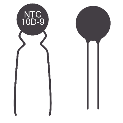
NTC stands for negative temperature coefficient, meaning that there is a negative correlation between temperature and resistance. Thermistor is derived from “thermal sensitive resistor”. A thermistor is a component that can measure temperature from the difference in electrical resistance when a resistive element is brought into contact with the object to be measured. It is characterized by the use of a metal oxide semiconductor as the resistive element.
Negative temperature coefficient (NTC) thermistors are the most versatile of all thermistors because the material is inexpensive and easy to process. They are high-precision thermistors because their resistance value changes even with minute changes in temperature. They are widely used in familiar home appliances and industrial equipment.
They are used as temperature sensors by detecting differences in resistance. Lead type, chip type, disk type, and thin-film type are available.
Uses of Negative Temperature Coefficient (NTC) Thermistors
Negative temperature coefficient (NTC) thermistors are used in a wide range of applications, from industrial applications to home appliances, due to their inexpensive characteristics. They are mainly used as temperature sensors.
- Internal temperature detection in smartphones
- Inrush current reduction in electronic circuit boards
- Temperature measurement in electronic thermometers
- Motor temperature monitoring in vacuum cleaners
- Temperature detection in refrigerators
1. Application to Smartphones
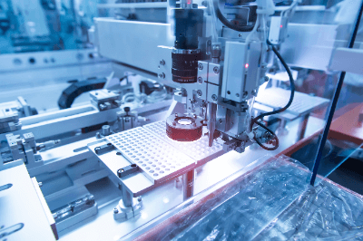
Smartphones use heat-sensitive components and components that lose accuracy due to heat, so it is important to prevent heat buildup. Therefore, the negative temperature coefficient (NTC) thermistor detects internal temperature changes and conveys the information to the IC. In addition to measuring room temperature, NTC thermistors are also used as temperature protection elements to protect circuits from overheating in order to stabilize circuits and prevent failures.
2. Inrush Current Reduction
In electrical and electronic equipment, a large current exceeding the steady-state current value may temporarily flow at power-on. This current is called inrush current. The reason for inrush current may be the initial charging of a large-capacity capacitor.
Negative temperature coefficient (NTC) thermistors are sometimes used to suppress inrush current at power-on by taking advantage of their high resistance value at low temperatures. As the temperature of the thermistor rises due to current loading, the resistance value decreases and power decreases as well.
Since the resistance value decreases as the temperature rises due to energization, power loss can be reduced compared with the use of fixed resistors. Therefore, negative temperature coefficient (NTC) thermistors are used as ICLs (Inrush Current Limiters) to protect circuits of electrical and electronic equipment by easily and effectively limiting inrush currents.
3. Temperature Measurement Circuits
Negative temperature coefficient (NTC) thermistors are widely used in temperature measurement circuits. Since this component detects temperature change by resistance change, it is often used in combination with other resistors. The most commonly used circuit configuration is to use a thermistor connected to a constant voltage source via a pull-up or pull-down resistor.
Principle of Negative Temperature Coefficient (NTC) Thermistors
The main component of the negative temperature coefficient (NTC) thermistor is ceramics, which is a semiconducting ceramics made by mixing and sintering oxides of manganese, nickel, cobalt, etc., with electrodes attached. There are N-type and P-type semiconductors depending on the doping substance.
Normally, the transfer rate of free electrons and holes decreases as the temperature rises. However, in negative temperature coefficient (NTC) thermistors, electrons in the valence band are transferred to the conductor by thermal energy, and the rate of increase of free electrons and holes in the conductor is greater than the rate of increase of free electrons and holes, resulting in lower resistance. Negative temperature coefficient (NTC) thermistors are characterized by a gradual decrease in resistance.
To make negative temperature coefficient (NTC) thermistors, raw oxides are mixed to make a uniform mixture and temporarily baked at 800°C to 1,000°C. They are then pulverized and the grains are sized. After crushing them, the grain size is increased to a size suitable for molding, and then they are formed into their final shape and fired at 1,300-1,500°C. Finally, electrodes are formed and the product is finished by coating with epoxy resin.
How to Select Negative Temperature Coefficient (NTC) Thermistors
Negative temperature coefficient (NTC) thermistors are selected according to application, dimensions, B constant, and resistance value. The application is the use for which negative temperature coefficient (NTC) thermistors are used. These include automotive and electronic board mounting applications. Select a thermistor according to its dimensions and the situation in which it is to be mounted.
The larger the B constant, will create a greater change in resistance with temperature. Therefore, products with a large B constant have high sensitivity, while those with a small B constant have low sensitivity.
The resistance value is the normal resistance value at room temperature (25°C). Generally, a product with a small resistance value should be selected for low-temperature environments, while a product with a large resistance value should be selected for high- temperature environments.