カテゴリー
category_usa

Tactile Switch

What Is a Tactile Switch?

A tactile switch is a switch whose actuator has a clicking feel.

Tactile switches are also called tactile switches, tactile switches, push-momentary switches, etc. Tactile switches are also called tactile switches, tactile switches, push-momentary switches, etc. The word “tactile” in tactile switch means “tactile sense.”

A tactile switch is a switch that is widely used as an input control for various electronic devices and home appliances, and energizes an electric circuit when the actuator is pushed in. When the actuator is pushed in, there is a clicking sensation, providing feedback by feel that a person has operated the actuator.

Since the human operator operates the switch repeatedly, the material and shape of the spring that serves as the movable contact point must be designed to ensure durability and stable operation over a long period.

Uses of Tactile Switches

The uses of tactile switches are the operating parts of various products, such as electronic equipment, home appliances, industrial equipment, and office automation equipment. There is also the purpose of making the person operating the switch aware that he/she is operating the switch in conjunction with the ON/OFF function of the switch.

For example, in order to emphasize the viewpoint of preventing malfunctions, there are long-stroke switches with a clear sensation of being pushed in through push operation, such as those mounted on car steering wheels and intercoms, while short-stroke switches such as power and volume buttons on smartphones and speakers, and medium-stroke switches on mice and game controllers, etc. are used. On the other hand, there are switches with short strokes, such as the power and volume buttons on smartphones and speakers, and medium strokes on mice and game controllers, depending on the uses of the device.

Principle of Tactile Switches

Tactile switches have a button-shaped movable contact called a push button (push plate) inside, and when a person pushes the push button, the movable contact makes contact with the lower fixed contact to energize the switch. The five main components of a tactile switch are the cover, pushbutton (push plate), film, movable contacts, and base.

1. Cover

The cover protects the internal structure together with the base. It is often made by pressing a metal sheet.

2. Push Button (Push Board)

Push buttons (push plates) transmit the force received by the part where the person pushes the actuator to the movable contacts via a film.

3. Film

The film is a thin plastic sheet that seals the contact area, preventing water and foreign matter from entering.

4. Movable Contact

The movable contact has a dome shape. When the pushbutton is pressed and the movable contact is pushed through the film, it makes contact with the fixed contact located on the base and current flows.

4. Base

The base is a plastic or other component with mounted contacts and terminals and serves as the foundation for attaching other components.

In a tactile switch mounted on a device, when a person presses the pushbutton, the fixed and movable contacts on the base are connected and conductive. When a finger is released from the pushbutton, the fixed and movable contacts are separated to open the switch. This is a momentary type switch that is energized only while the pushbutton is pressed.

Other Information About Tactile Switches

1. Integration With Haptics

Tactile switches have a wide range of applications in home appliances, information equipment, industrial equipment, and automotive applications, but one area of application that has recently been attracting attention is in the field of “haptics” or “tactile technology. Haptics is a technology that artificially reproduces the human sense of touch through vibration, and this technology is attracting a great deal of attention in fields such as VR/AR, game consoles, and healthcare.

VR technology needs the boost of technology equivalent to the sense of touch to improve the reality of virtual space in the world of metaverse, and in the world of healthcare, haptics is attracting attention as a useful technology for remote treatment. Some manufacturers are now focusing on the integration of haptics with not only the click feeling based on the technology developed for tactile switches, but also on the ability to express vibration through the use of spring resonance structures and other technologies.

2. Application Development of Piezoelectric Element Technology

Other examples of adding vibration expression to thin switches include the application of piezoelectric element technology to dome-shaped movable contacts. The human feedback technology of the click feeling of tactile switches has recently been transformed into a more user-friendly and attractive advanced technology with the addition of new vibration expression.
カテゴリー
category_usa

Rotary Grinder

What Is a Rotary Grinder?

A rotary grinder is a machine that places a workpiece, the object, to be processed, on a rotating round table and grinds it with a grinding wheel.

Rotary grinders are characterized by their suitability for grinding workpieces with relatively large areas and by their ability to grind numerous workpieces by placing them on the table at once. Generally, in surface grinding, grinding is done by the grinder moving to the left or right, while the type of grinder that rotates is distinguished by the term rotary grinder.

Uses of Rotary Grinders

Rotary grinders are used for efficiently grinding multiple workpieces with relatively large cross sections at a time. Specific workpieces include large quantities of substrates, wafers, and plates.

However, the throughput related to workpiece grinding depends greatly on the size of the rotary grinder’s table and the size of the rotating grinding wheel, so it is important to check the specifications of each manufacturer carefully.

Principle of Rotary Grinders

The principle of rotary grinder is to grind a large surface of a workpiece at once by placing multiple workpieces side by side on a large rotating round table and applying a rotating grinding wheel such as a diamond cup from the top surface.

Since this method allows a relatively large grinding area to be secured, it is more efficient and quicker than conventional surface grinding, in which grinding is carried out by moving the workpiece from side to side.

However, the disadvantages of this method are that it is relatively difficult to achieve accuracy and that it sometimes requires time for preparation, such as setting the workpiece. However, since it is a grinding method that can process large quantities of workpieces at a time, it is necessary to use a rotary grinder according to the purpose and application of the grinder.

Other Information About Rotary Grinders

1. Difference Between Grinding and Polishing

In general, the term “grinding” refers to the process of physically shaving the surface of a workpiece to remove material, while “polishing” refers to the process of polishing the surface of a workpiece to bring out its mirror-like surface. However, in some industries, the two are used without distinguishing between the two, in which case the term “polishing” is generally used to encompass grinding.

The process of polishing out a mirror surface, which is inherent to polishing, is also known as lapping or buffing, and often utilizes proprietary abrasives as well as grinding wheels.

2. Difference Between Rotary Grinder and Lapping Machine

Lapping machines are similar in their configuration to rotary grinders in that they are machines that set multiple workpieces on a rotating table and grind them. However, lapping machines are often used when the workpieces need to be ground to a high precision and mirror finish level.

The lapping machine has a method of sandwiches the workpiece between the upper and lower ref plates and uses the “principle of three-sided grinding” to improve the precision of its flat surface. Another major feature of the lapping process is that a liquid abrasive is poured into the workpiece to polish it, which is different from the method used to process workpieces on rotary grinders.

However, this method requires time and labor for polishing and finishing, so it is not suitable for mass processing in a short period of time, like rotary grinders.

3. Example of Grinding Accuracy Improvement on a Next-Generation Rotary Grinder

Some manufacturers of rotary grinders, with their technological innovations, are dealing with the next generation of high-end models that aim to achieve the accuracy of a lapping machine while still being a rotary grinder. Although their mechanisms are very complex, the following examples of improvements have been applied to increase grinding accuracy and finish to mirror level while still having the features of a rotary grinder.

  • Permanent electromagnet, a chuck that is not affected by heat, is activated after the workpiece is set.
  • Equipped with a function to monitor and FB the amount of grinding wheel cutting
  • Applies technology to control the inclination of the table on which the workpiece is mounted with extremely high precision

This is an example of a next-generation rotary grinder with a processing speed and workability closer to that of grinding than to that of polishing, which is unique to rotary grinders.

カテゴリー
category_usa

Robot Cable

What Is a Robot Cable?

Robotics Cables

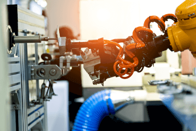
Robot cables are used to transmit power and signals to robot arms and industrial robots.

Compared to general-purpose cables, they are characterized by extremely high durability against repeated bending and twisting. A variety of product cables are available on the market, including those that can handle high currents, those with small diameters, and those that bundle power and signal cables into a single cable.

Uses of Robot Cables

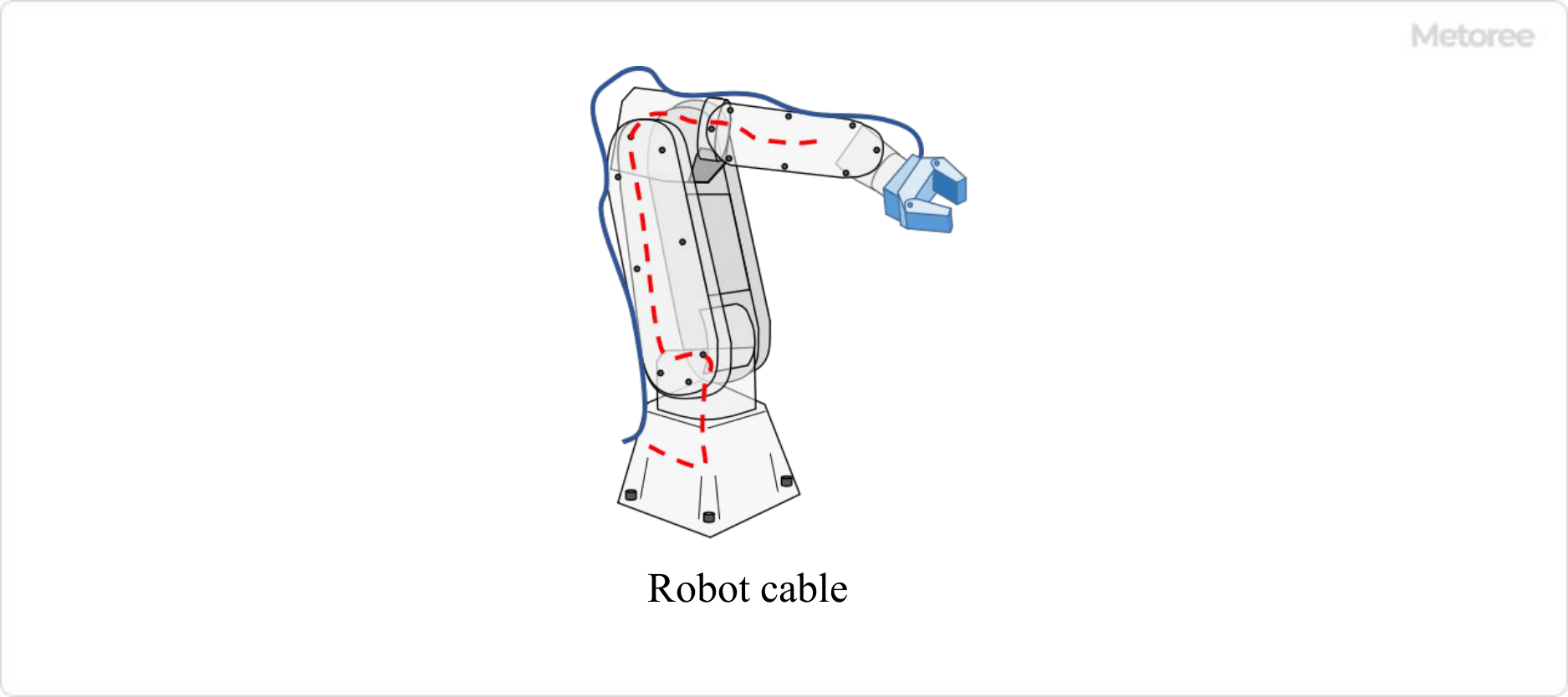
Figure 1. Uses of robot cables

Figure 1. Uses of robot cables

Robot cables are used in the part connecting the robot controller to the robot arm (manipulator part) and inside the robot arm. Robot arms are used in a wide range of industries, including automobiles, precision instruments, home appliances, and machine parts. When selecting a product, it is necessary to analyze the degree and number of repetitive bending and twisting that will occur based on the operation of the robot to be used, and purchase a product that satisfies these requirements.

In addition, specifications such as size (diameter and length), current and voltage, signal transmission speed, and noise performance must also be considered.

Principle of Robot Cables

Figure 2. Structure of robot cable

Figure 2. Structure of robot cable

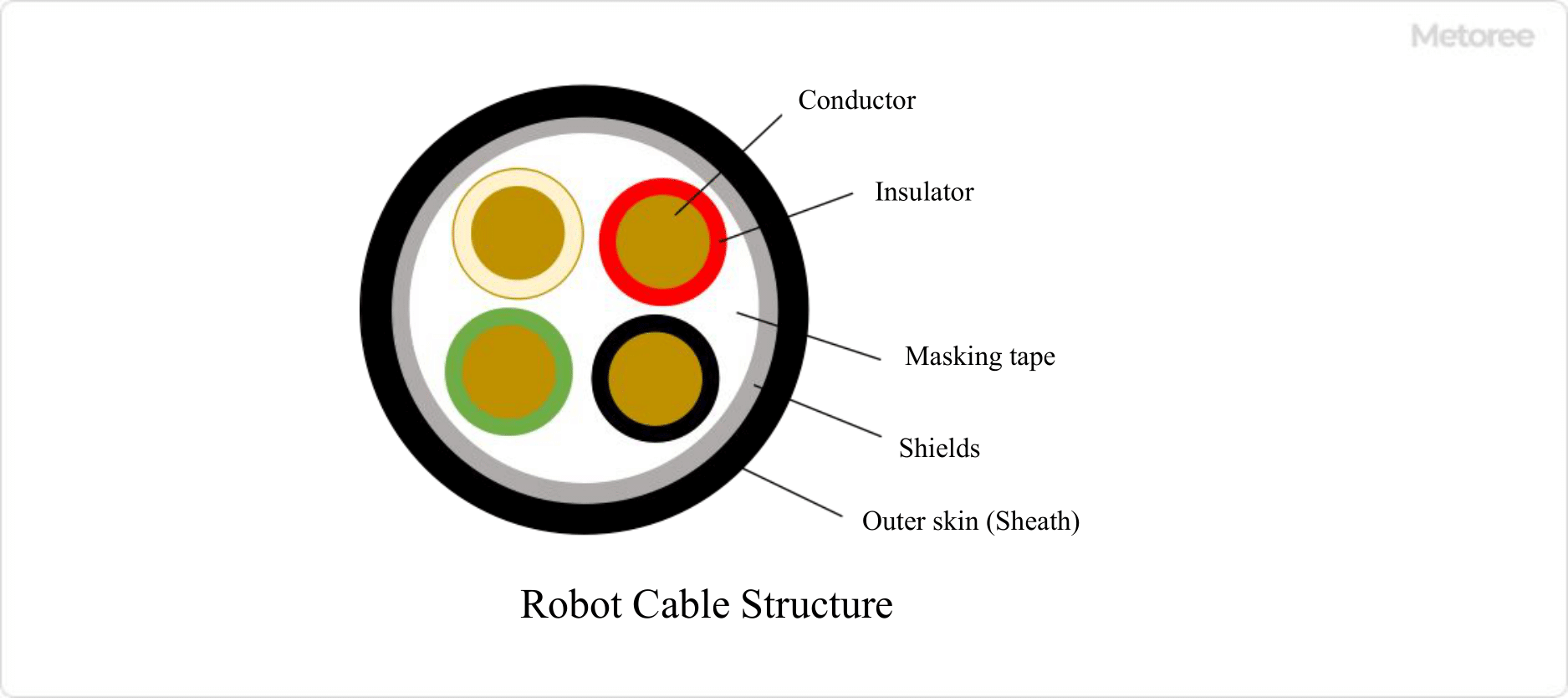
Robot cables consist of multiple bundles of conductors covered with an insulating film, which are surrounded by shielding tape and an outer film.

The components of a 4-conductor robot cable serve the following functions:

  • Conductor: Copper wire that carries current and signals.
  • Insulator: An insulating film that prevents current flowing in a conductor from leaking out.
  • Shielding tape: Tape that binds each individual wire.
  • Shield: The part that protects from external noise and is a jacket of copper or aluminum.
  • Outer skin (sheath): An outer film that protects the cable from trauma and oil.

The robot cable is connected to the robot controller at one end and to the operating part of the robot at the other end. The robot is operated by transmitting signals and current from the robot controller to the robot.

Since the robot arm frequently bends as it moves, fatigue strength and abrasion resistance are highly demanded. Durable materials (such as PVC) are used to increase fatigue strength and specially treated vinyl or fluororesin coatings are used to increase abrasion resistance.

Other Information on Robot Cables

1. Robot Cable Standards

Robot cable standards vary from country to country, and robot cable manufacturers adhere to standards specific to each country.
The following are examples of standards for robot cables in different countries.

Japan
PSE is a standard that conforms to the Electrical Appliance and Material Safety Law (PSE) and JIS/JCS standards, which specify the insulation and flame resistance of electric cables, etc. JIS/JCS standards aim to standardize cable products.

China
The China Compulsory Certification (CCC) standard is a certification standard for safety, EMC, and environmental protection for products sold in China. This CCC is mandatory in order to sell products in China.

EU
The CE marking is a standard that, once obtained, allows the product to be sold in a total of 31 countries (27 EU member countries and 4 EFTA member countries).

Germany
The TÜV certification (TÜV) is a product safety standard established by TÜV Rheinland, a private German company.

America
UL certification is a product safety standard established by the Underwriters Laboratories Inc. Although acquisition itself is optional, most products sold in the U.S. have acquired this certification, so it is virtually mandatory.

Canada
CSA certification is a product standard established by The Canadian Standard Association. As in the US, obtaining CSA certification is voluntary, but for operational purposes, products cannot be sold unless they are CSA certified.

2. Measures to Prevent Robot Cable Breakage

Figure 3. Measures to prevent robot cable breakage

Figure 3. Measures to prevent robot cable breakage

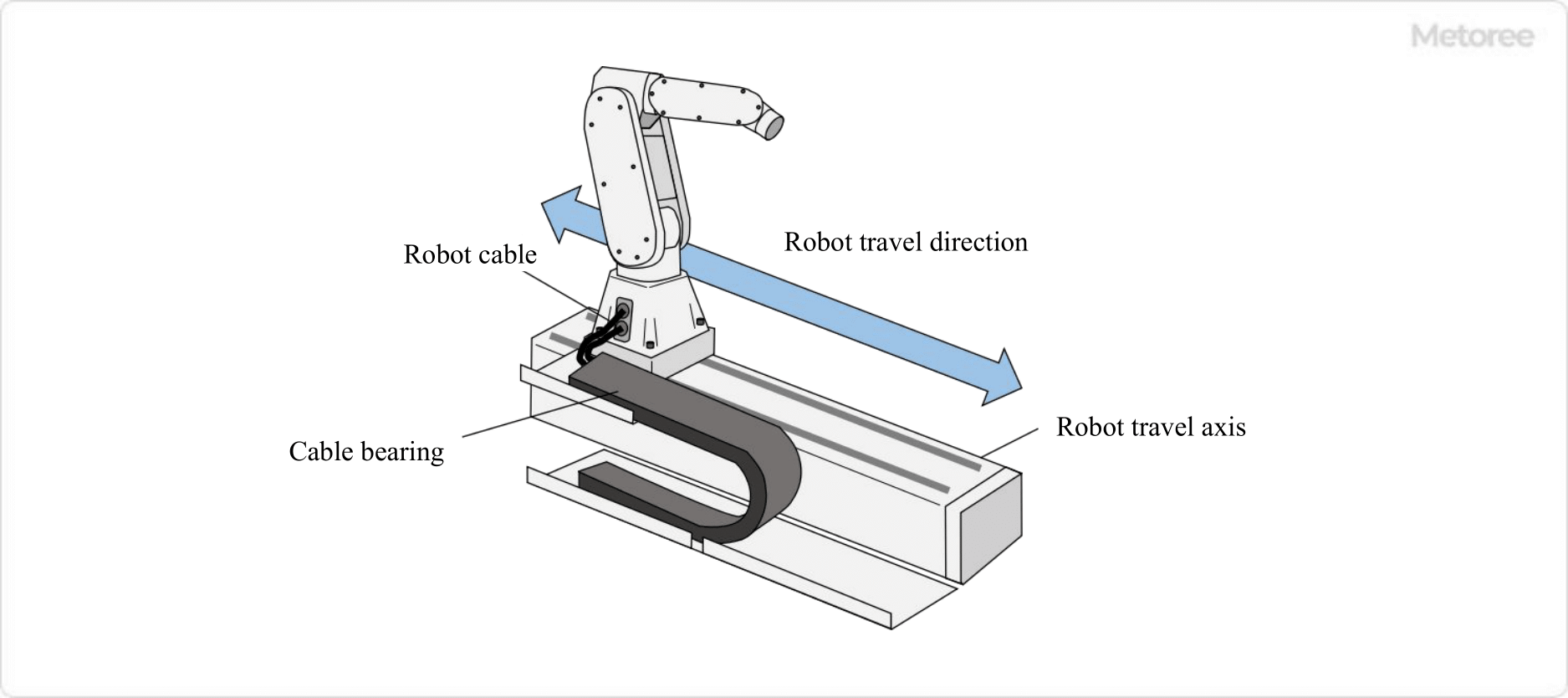
When a robot is installed on a robot traveling axis, there may be cases where the cable gets caught in the moving parts of the traveling axis and breaks.

As a countermeasure, a cableveyor is installed to protect robot cables. Cableveyors are like racks that hold robot cables and air hoses. This ensures that the cables and hoses between the moving equipment and the fixed end are supported and guided, preventing them from becoming entangled in moving parts. Cableveyor bends are designed to bend only in one direction at a fixed radius.

カテゴリー
category_usa

Image Processing Equipment

What Is Image Processing Equipment?

Image processing equipment is a device that inspects the appearance and dimensions of an object based on images obtained from a camera or sensor.

Image processing equipment is used as an alternative to visual inspection by inspectors. Visual inspection is used to maintain and guarantee the quality of parts and products. Image processing equipment is important to prevent variations in inspection accuracy due to individual differences and fatigue.

Uses of Image Processing Equipment

Image processing equipment is used in manufacturing lines in a variety of fields. The main applications are as follows:

  • Inspection for scratches, stains, and defects on parts, etc. in the factory
  • Over/under inspection of the number of products and parts to be packed
  • Inspection of products and parts for dimensional and size differences
  • Color inspection of products and parts

The introduction of image processing equipment has prevented human error and increased the speed of stable 24-hour operation and inspection.

Principle of Image Processing Equipment

Image processing equipment consists of an image input system consisting of a camera or sensor and lighting, and an image processing device. The principle of image processing equipment is to determine whether a product is acceptable or not by extracting information, such as features from images captured by a camera, and comparing it with the registered information on good products.

The functions of the image input system and image processor are as follows:

1. Image Input System

The image input system consists of lighting, a camera, and a lens. For the image input system, it is necessary to select, install, and control the most appropriate equipment (area camera or line sensor camera, indirect or direct illumination, etc.) according to the object, object transport conditions, and inspection objectives (size of defects, degree of contamination, etc.).

2. Image Processing Equipment

Image processing equipment performs image transformation, image deformation, feature extraction, and other processing on images obtained from the image input system. Image processing equipment registers the criteria (numerical values, ranges of feature values, and graphic patterns) for judging a product as good beforehand, and compares them with the feature values obtained from the image input system to make a pass/fail judgment.

How to Choose Image Processing Equipment

For image processing equipment, the image input system and image processing equipment should be selected according to the object to be inspected, the specifications of the transfer line, and the purpose of the inspection. In selecting image processing equipment, it is necessary to quantify the benefits, such as improved productivity and reduced workload for personnel, in relation to the costs incurred, so that cost-effectiveness can be obtained.

The following points should be considered when selecting image processing equipment:

1. Image Input System

Lighting
Illumination that is even and stable in brightness makes image inspection stable. It is necessary to select the type of light source, the type of filter, the way the light is applied, and the number of units so that the item to be inspected can be emphasized.

For example, when photographing uneven metal surfaces, use positive reflection type lighting; when prone to halation, use diffuse reflection type lighting.

Camera
Depending on the item to be inspected, select from color cameras, monochrome cameras, high-speed cameras, line sensor cameras, contact image sensor cameras, etc. Color cameras are employed when inspecting the color of products or parts.

Color cameras are more expensive than monochrome cameras. If the color of the object to be inspected is simple, a monochrome camera and a color filter may provide a stable inspection. When selecting a camera, do not simply think of a color camera for color inspection.

A high-speed camera is used when the object to be inspected moves at high speed, causing blurring with a normal camera. When a high-speed camera is used, the lighting must be bright.

Line sensor cameras and contact image sensor cameras are employed when the object to be inspected is a sheet-shaped object or a circular or cylindrical rotating object. A contact image sensor camera is a camera that integrates a fixed-focus lens and illumination, and is effective when the distance between the object to be inspected and the camera is stable.

Lens
Lens selection is based on focal length and object depth. For image inspection, the field of view must be set so that the inspection object can be captured with the necessary accuracy.

The focal length is the distance from the lens to the image element. The focal length is the distance from the lens to the image sensor of the camera. The focal length is determined by the size of the object to be inspected (field of view), the distance between the lens and the object to be inspected, and the size of the image sensor.

Depth of field is the range in which the focused inspection object remains in focus even if the object moves away from or closer to the camera. The deeper the depth of field, the more in-focus the image will be, even if the distance between the object to be inspected, and the camera varies.

In a production line, there are restrictions, such as installing the camera in such a way that it does not interfere with other equipment. The lenses used in image processing equipment must be selected to provide the focal length and depth of field that meet the imaging conditions required for inspection. In addition, lenses with short focal lengths will cause distortion in the image, so it is necessary to confirm that this will not affect the inspection accuracy.

2. Image Processing Equipment

Image processing equipment is selected based on the accuracy required for the inspection (size of flaws, degree of irregularity, length error, recognition rate of characters and bar codes, etc.) and speed (whether the inspection can be completed within the time allowed by the production line or faster than the current inspection speed).

カテゴリー
category_usa

Substrate Divider

What Is a Substrate Divider?

A substrate divider is a piece of equipment that divides a number of substrates on a sheet board at the same time.

The use of substrate dividers increases production efficiency. There are several types of dividers, including router processing, dicing processing, stamping, and pressing and cutting. Depending on the purpose, there are facilities for low-volume or high-volume production, and initial costs can be low or high.

Printed circuit boards include glass, composite, and paper substrates, and substrate dividers can process all of them. However, there are substrate dividers that cannot process certain substrates, so it is necessary to select the appropriate substrate divider for your application.

Uses of Substrate Dividers

Substrate dividers divide sheet substrates into numerous substrates. Examples of substrate dividers include router dividers and dicing dividers, as well as press dividers and push-off dividers.

Router Splitter
Using a router tool for dividing the board, rotate the tool to divide the position to be divided.

Dicing and Dividing Machine
While rotating the grinding wheel, divide the specified position.

Press Divider
The blade for dividing is inserted in accordance with the dividing position of the board, and the board is divided by pressing.

Push-Cut Type Divider
For small production runs, substrates are passed between the upper and lower rotating circular blades and divided by the gap between the blades.

Principle of Substrate Dividers

Since the principle of substrate dividers varies from type to type, we will divide them into the following three categories.

1. Router Splitter

Router dividers can divide PCBs with a thickness of 0.4 mm to 1.6 mm, and can break in vertical, horizontal, diagonal, and other directions. Entering the coordinates you want to split into the device makes it easy to change the model of the board, but there is a lot of powder due to the router process. When splitting a board, whiskers of fibers of the board appear on the split surface, but cutting the board twice can reduce them. The speed of splitting is slow due to the limited height of the fixtures to be mounted on the board.

2. Press Division

Press partitioning can be done quickly because all the partitioning points on one piece can be partitioned in one shot at the same time. Even if the components to be mounted on the printed circuit board are high, they can be divided. Less powder is generated during division, making it suitable for high-volume production. However, the production cost is high because a die for dividing is required, and the stress on the board generated during dividing is high.

3. Push-Off Division

Push-off dividing is suited for cases where the production volume is not large, since the initial investment in router and press dividing is large. It is not suitable for dividing paper substrates.

Types of Substrate Dividers

Substrate dividers can be classified by method and target workpiece: For V-groove applications, they are classified into upper/lower disk cut type and linear split type. For perforation, there are local punching type, precision press blade type dividing type, and router type.

Substrate dividers can also be classified by substrate layout. They can split V-grooves near the edge or in the center, divide boards horizontally and vertically in a matrix, divide boards with cutouts in the middle of V-grooves or power boards with tall components around V-grooves, divide small amounts of perforated boards with few connections, and divide large amounts of assembled boards with many connections.

How to Select a Substrate Divider

Compatible equipment should be selected according to the method, target workpiece, and board layout.

The upper/lower disc cut type uses upper/lower rotating circular blades to cut V-grooves. There are two types: manual and motorized. In the manual type, the blade spontaneously turns by the force of the blade pushing against the substrate, while in the motorized type, the blade is forced to turn. The linear split type is a method that combines a linear blade and a rotating circular blade. The lower blade can be set to split the V-groove portion of the substrate, and the cutting line does not move.

The local punching type uses a T-shaped blade to punch off the connection. It is small and easy, but not efficient and not suitable for mass production processing. In the precision press-blade parting type, the upper and lower press-blades are used to punch out the connection in a single operation. This method is suitable for mass-production processing of assembled boards because the connections can be broken up at once. In the router type, a high-speed rotating router bit is used to shave off the connections. This method places less stress on the board, but requires the collection of chips.

カテゴリー
category_usa

Proximity Switch

What Is a Proximity Switch?

Proximity Switches

A proximity switch is a non-contact switch that can detect the proximity of a metallic object.

It detects the proximity of a metallic object using electromagnetic induction, etc., and outputs as a contact point. There are various lineups of power supply requirements and contact configurations required for proximity switches, and they must be selected according to the situation.

Uses of Proximity Switches

Proximity switches are used in factories and other equipment to detect the drive status of machines. Specific uses of proximity switches are as follows:

  • Detection of hydraulic press operation
  • Motion detection for industrial robots
  • Open/close status detection of critical valves and doors
  • For servomotor positioning detection
  • Rotation speed detection of rotating equipment

Machine operation is detected at the above locations and alarms are issued or sequence control is implemented. In recent years, waterproof and heat-resistant products are also available. Since the machine status can be easily detected by attaching a piece of iron, etc., they are often used for large equipment in the iron and steel industry.

Principle of Proximity Switches

There are various types of proximity switches, but inductive proximity switches are the most commonly used. Inductive proximity switches consist of an electromagnetic coil, an oscillator circuit, and a casing.

1. Electromagnetic Coil

An electromagnetic coil is a component that generates an induced current in an approaching metal. The electromagnetic coil always outputs a high-frequency magnetic field, and electromagnetic induction is generated when a metal object such as a piece of iron comes close to it. This electromagnetic induction generates an induced current in the metallic object.

2. Oscillation Circuit

The oscillation circuit is a component that feeds back the power output by the electromagnetic coil. The induced current generated inside a metallic object is converted to heat within the metal, resulting in a power loss. The oscillation circuit detects this power loss and sends it to the output circuit. The transmitter circuit and output circuit are configured on the same board, and the output circuit outputs the power as a contact signal to the outside.

3. Casing

The casing is the outer frame that protects these circuit components. The casing is often threaded and secured to the mechanical device with a locknut. The casing is usually filled with resin to insulate the casing from the circuit components.

Other Information on Proximity Switches

1. Positioning of Proximity Switch

When using proximity switches, the mounting position must be determined. Proximity switches are non-contacting and output a contact point when they detect the proximity of a metal or other contact object. Positioning of proximity switches means adjusting the proximity distance to the object to be contacted by adjusting the position of the proximity switch.

Proximity switches have a fixed detection distance according to their specifications. The proximity switch output operates when the object to be detected enters this detection range. If the proximity switch is too far away, it will not operate, so it is necessary to determine the proper distance by adjusting the position of the proximity switch.

Products are also available that indicate the response of the proximity switch by emitting LED light. Such products are convenient for positioning because the output operation can be visually observed at close range. It should be noted, however, that the LED emission pattern differs depending on the product. Some products emit light even in locations that are within the detection range but not yet in the output operation range. Such products often emit multiple colors.

For example, there are products that emit orange when the detected object is in the detection range and green when the detected object is brought even closer to the proximity switch for output operation. Therefore, it is important to read the instruction manual of the product to be used carefully .

2. Failure of Proximity Switch

When a proximity switch malfunctions, a failure of the proximity switch is suspected. There are many possible reasons for the failure, but the two most common causes are as follows:

Power Failure
Check that the power supply to the proximity switch is correct using a tester or similar device. If there is no power supply, the cause is the loss of power. If the power circuit or grounding is not correct, there will be no signal output even if the object is to be detected approaches. In this case, disconnection of the power circuit or ground wire or failure of the power supply unit is suspected.

Misalignment of Proximity Switch
Misalignment of the mounting position may also be a cause. If misalignment causes the switch to move away from the detection range, it can be restored by adjusting the position. However, if the object to be detected comes too close and contacts the proximity switch, the proximity switch may be damaged physically .

If physical damage is the cause, the proximity switch must be replaced. Other possible causes of proximity switch failure include noise and overvoltage.

3. Proximity Switch and Detectable Object

Proximity switches are mainly used to detect metallic objects. The reason is that they use electromagnetic induction as their operating principle. In order to generate electromagnetic induction, the piece of iron to be detected must be conductive.

However, in recent years, inductive proximity switches have been developed that can sensitively detect even metals that are not conductive.

カテゴリー
category_usa

Photoelectric Element

What Is a Photoelectric Element?

Photoelectric Elements

A photoelectric element is the general term for electronic elements responsible for the conversion between light energy and electrical energy.

Broadly speaking, there are light emitting elements that convert electrical signals into optical signals and light receiving elements that convert optical signals into electrical signals. Light-emitting elements emit light when an electric current is applied, and light-emitting diodes are a typical example.

Light-emitting diodes are typical examples. Light bulbs and fluorescent lamps also emit light when an electric current is applied, but light-emitting elements are limited to those using semiconductors and do not include them. Photodetectors receive light and generate an electric current, of which solar cells are an example.

Uses of Photoelectric Elements

Photoelectric elements are used in a great many devices in fields that utilize light. In the case of light emitting elements, light-emitting diodes can be used in the light emitting parts of lighting equipment, photo interrupters and other sensors as light sources for object detection, semiconductor lasers as signal light sources in the field of optical communications, and many other examples can be given of their use.

In addition to the solar cells mentioned above, examples of photodetectors include illuminance meters, exposure meters for cameras, pickups for CDs and DVDs, image sensors for photographic equipment, and sensors that detect reflected light from objects in photo interrupters.

Principle of Photoelectric Elements

The principle of a light emitter and a light receiver are very different.

1. Luminous Element

The basic structure of a light-emitting diode as a representative light-emitting device is a PN junction, which consists of a P-type semiconductor (with the majority of holes as carriers) and an N-type semiconductor (with the majority of electrons as carriers).

When a forward voltage is applied to a light-emitting diode, electrons and holes move through the light-emitting diode chip, causing an electric current to flow. When the electrons and holes collide during the transfer, they recombine, but in this state, the energy of the electrons and holes is less than the combined energy they originally possessed.

This reduced energy is converted into light and emitted outside the semiconductor. This is the principle of luminescence.

2. Light Receiving Element

Photodetectors are based on the photoelectric effect. The photoelectric effect refers to what occurs at the PN junction of the semiconductor. Even if both ends of the photodiode are shorted, an electric field is formed at the PN junction and a potential gradient is generated within it.

When light is irradiated in this electric field, its energy generates electrons and holes, but the potential gradient causes the electrons to move immediately. The stronger the light (the greater the number of photons) will produce a greater current.

Applying a reverse bias voltage to the PN junction widens the electric field, resulting in the generation of electrons and holes in a wider area. Also, since the slope of the potential becomes stronger, the carriers move faster and a faster response can be expected.

Types of Photoelectric Elements

Semiconductor elements classified as photoelectric elements include the following:

1. Luminous Element

Light-Emitting Diode
Many light-emitting diodes with different emission wavelengths from the near-infrared to visible regions have been commercialized, and demand for blue LEDs, in particular, is growing very rapidly as they are used in lighting fixtures. On the other hand, light-emitting diodes emitting near-infrared light are used as devices for optical communications.

Semiconductor Laser
It can emit light that is stronger and more coherent than ordinary LEDs. Familiar applications include laser pointers that take advantage of its linearity, and light sources for projectors that take advantage of its high luminous flux and single wavelength.

OLED (Electro Luminescence)
It is used for thin and lightweight displays such as TVs and viewfinders for photographic equipment.

2. Light Receiving Element

Photodiode
There are various applications, such as sensors for illuminance meters and other measuring instruments that measure the intensity of light, and sensors for detecting objects with light.

Phototransistor
It is a sensor with higher sensitivity than a photodiode because it receives light in the base region of the transistor and the current generated there can be amplified and extracted. It is mainly used in the light receiving part of photo interrupters.

Image Sensors
A sensor used to create image data by projecting an image onto numerous photodiodes arranged in a flat pattern. They are used in the imaging section of cameras that take still and moving images.

Although they are very large and expensive as semiconductor devices, they have become widely used, replacing the imaging tubes and photographic films that were once used.

カテゴリー
category_usa

Tabletop Drilling Machine

What Is a Tabletop Drilling Machine?

Desktop Drilling Machines

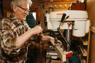
A tabletop drilling machine is a small drilling machine installed on a tabletop.

Holes are drilled perpendicular to the material using drill bits attached to a spindle rotated by a motor. Tabletop drilling machines are used for manual drilling and the material is fixed to the table.

They are easy to carry and small enough to work on a tabletop without taking up too much space, effectively improving work efficiency. However, it is necessary to select the appropriate drill bit and set the appropriate feed rate according to the material.

Uses of Tabletop Drilling Machines

The following are some of the typical uses of tabletop drilling machines:

  • Drilling
    Drilling of metal parts, furniture parts, etc., drilling of wood and plastic
  • Tap (Threaded Hole Production)
    Production of screw holes in metal and aluminum plates, etc.
  • Groove Carving and Surface Finishing
    Groove carving and groove expansion on metal and plastic parts, surface finishing of parts by cutting and polishing
  • Cutting of Metals and Plastics
    Cutting of metal and rustic bars and plates, shaping of materials
  • Grinding and Polishing
    Grinding and polishing metal and plastic parts, surface finishing using grinding wheels and abrasive tools
  • Microscopic Processing of Electronic Components, Etc.
    Drilling holes in circuit boards for mounting and removal of electronic components

Principle of Tabletop Drilling Machines

The process of drilling holes with a tabletop drilling machine is as follows:

1. Fixing of Materials

Place the material in the exact position on the tabletop drilling machine table. Secure the material using a clamp or vise to minimize misalignment and movement. Unsecured material is dangerous because it can cause problems with machining accuracy and safety.

2. Drill Bit Selection

Select the appropriate drill bit for the hole size and material. Drill bits come in different diameters and types and should be selected to suit the material to be processed.

3. Installation of Drill Bit

Install the selected drill bit into the drill chuck of the drilling machine. It must be properly tightened during installation to ensure that the drill bit is safely secured.

4. Setting of Machining Conditions

Set the appropriate rotational speed and feed rate according to the type of material to be processed and the size of the drill bit. Drilling machines are equipped with dials and levers for adjusting rotational and feed speeds.

5. Start of Drilling

After setting the processing conditions, operate the switch or lever to turn on the motor and rotate the drill bit. After lightly placing the tip of the drill bit against the surface of the material, begin lowering the drill bit while applying pressure little by little.

6. Hole Machining

A hole is drilled while advancing the drill bit little by little, and when a certain depth is reached, the drill bit is pulled up to remove chips. This prevents the accumulation of chips and chips and ensures accurate drilling.

7. End of Drilling

When the drilling is complete, stop the drilling machine motor and remove the drill bit from the material while slowly pulling it up. When pulling up the drill bit, use the drilling machine’s moving handle or crank to move the drill bit to the exact position.

8. Material Removal

Remove the material from the drilling machine after drilling is complete. Loosen the clamps and vices and remove the material while handling it carefully. Care must be taken when removing the material to prevent injury or damage.

Structure of Tabletop Drilling Machine

The basic structure of a tabletop drilling machine consists of the following elements:

1. Base

The base of a tabletop drilling machine is the foundation of the machine. The base is made of cast iron or steel and is the part that ensures the overall stability of the drilling machine.

2. Spindle

The spindle is the central axis of the drilling machine and holds and rotates the drill bit. The spindle is connected to a motor, which transmits the rotational force. It also has a mechanism (quill) that can be moved up and down to adjust the position of the drill bit.

3. Drill Chuck

The drill chuck is attached to the spindle and secures the drill bit. Drill chucks generally come in keyed or keyless chuck form and tighten and secure the appropriate size drill bit.

4. Quill

The quill is the component that controls the vertical movement of the spindle and the drill bit. There are two types of quill: manual and electric. In the manual type, the quill is rotated and moved up and down to adjust the depth of the drill bit, while in the electric type, the quill is automatically moved up and down by a motor.

5. Table

The table is a flat surface on which to place the material and is positioned under the drill bit. The table can be moved up, down, left, and right, allowing precise positioning of the material. Clamps or vises are used to secure the material on the table.

6. Motor

The motor is the power source of the tabletop drilling machine and rotates the spindle. Generally, electric motors are used, and the performance of the motor determines the rotational speed and torque, which affect the efficiency and accuracy of the machining operation.

Other Information About Tabletop Drilling Machines

1. Advantages of Tabletop Drilling Machines

Tabletop drilling machines are small enough to be used where work space is limited and lightweight enough to be easily moved and stored. Another advantage is that they are easy to handle, even for beginners. They are relatively simple to operate and suitable for basic drilling. Another advantage is that the machine is installed on a workbench, so the workpiece can be easily secured.

In addition, tabletop drilling machines are usually equipped with a drill chuck that can accommodate various sizes of drill bits to drill holes of different sizes. By selecting drill bits according to the material and processing purpose, tabletop drilling machines can work with a wide range of materials, including wood, plastic, and metal.

2. Disadvantages of Tabletop Drilling Machines

Tabletop drilling machines are small and cannot process large workpieces. Because of the limited working space, it is difficult to fix large materials or long workpieces, and the dimensions of the workpiece are restricted.

It is mainly suited for light or precision work, but not for drilling large quantities of holes or processing heavy materials. It is limited for long-time continuous use or high-load work. Because they specialize in working within a limited machining envelope, other types of machine tools may be required when machining complex shapes or angles.

Some tabletop drilling machines have limited motor power. They are limited in their ability to machine at high speeds and high loads, and more powerful machine tools must be selected when speed and power are required.

3. Operating Method of Tabletop Drilling Machines

Manual
The manual type requires the operator to adjust the machining accuracy manually by moving the spindle up and down, and moving the table by hand. The operator can adjust the height of the quill and table according to the size and shape of the material to be machined.

While the manual type offers greater flexibility in adjusting to the material to be machined, it also requires more time for machining, resulting in lower productivity.

Automatic (Door, Gun, Etc.)
The automatic type is capable of high-precision machining because the quill and table are operated automatically. All the operator has to do is set the material and the machine automatically processes it. The automatic type is expensive because it requires advanced control technology. The automatic type is suitable for mass production and is best suited when high-precision machining is required.

カテゴリー
category_usa

Current Logger

What Is a Current Logger?

A current logger is a device that records current values while measuring them. Current loggers are sold as products by manufacturers of measuring instruments and store current values in memory while measuring and displaying them.

The unit of current is mainly A (ampere) or mA (milliampere), which is displayed on the interface panel. Some products offer a choice of sampling rates, with some having sampling rates as high as 100 times/second (100 Hz). Various types of power loggers are available, and there is a need to select the appropriate instrument depending on the desired measurement accuracy.

Uses of Current Loggers

Current loggers are measuring instruments used primarily for current measurement. Handheld loggers are also available, and in most cases are carried and used.

  • Confirmation of energization in PC repair
  • Pre-installation check of semiconductor devices in board mounting
  • Maintenance of production equipment
  • Confirmation of commissioning of electrical work
  • Temporary measurement for production machinery management
  • Monitoring of lithium-ion batteries (cell-by-cell )

Principle of Current Loggers

Current loggers are divided into several parts: the clamping section, transmission wiring, interface panel, and recording media. The principle of the clamping section is the same as that of a current transformer. The main part is an arc-shaped iron core that can be opened and closed by hand. It clamps the measuring current path as the primary winding and conducts the current to the transmission wiring as the secondary winding.

The transmission wiring is a common copper wire covered with a vinyl or other sheath. Some have a dedicated connection plug at the end, while others are pulled directly into the logger. Measured values are checked and set via the interface panel.

Some devices also allow the sampling rate, recording format, etc. to be set via this panel. Increasing the rate allows for more detailed recording, but it does not allow for long-term record keeping. Measurement results are written and stored on the recording media as needed.

USB flash memory or SD cards are used as recording media. CSV or txt files are often used as the output format. The clamp section above can only measure AC power.

For DC power supply measurement, a Hall element or similar device using the Hall effect is used. The Hall effect is the principle that an electromotive force is generated when a magnetic field is generated perpendicular to a conductor through which a current flows. Hall elements use this Hall effect to convert the magnetic field generated around an electric current into a voltage.

Current loggers using a shunt resistor may also be used to measure precise current values. A shunt resistor is a low-resistance resistor that is inserted in series with a shunt resistor in the measurement circuit. The current is calculated by measuring the voltage at both ends of the shunt resistor.

Hall elements and current transformers can measure current while the circuit is energized, but shunt resistors require the measurement circuit to be opened once. Because of their versatility, current loggers that use Hall elements or current transformers as the sensing element are generally used. The unit of current is A (ampere). Units used for measurement include kA (kiloampere), A (ampere), and mA (milliampere).

Since current loggers use analog signals as input data, noise may cause inaccurate measurement results. To improve detection accuracy, it is important to take measures, such as noise elimination of the wiring path, to avoid noise.

Other Information on Current Loggers

Origin of Current Logger

A log is a word that means a daily record, and the object that stores the record is called a logger. For example, a blog is an abbreviation of a weblog, which means to keep a diary on the web. Thus, a current logger is an object that records electric current.

カテゴリー
category_usa

Conductive Mat

What Is a Conductive Mat?

Conductive Mats

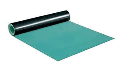
Conductive mats are used to discharge static electricity gradually that has been charged on the human body.

They are often laid on the floor and used in workshops, factories, laboratories, and clean rooms. In some cases, durability and abrasion resistance are required, and regular maintenance is necessary.

Uses of Conductive Mats

Conductive mats are made of conductive materials and are used to discharge static electricity, seal electromagnetic waves, and prevent damage to equipment caused by static electricity.

1. Prevention of Static Electricity

Conductive mats are placed on floors to reduce the risk of static electricity generation and discharge. They are especially used in workshops, factories, and clean rooms to facilitate the discharge of static electricity from people and equipment.

2. Electromagnetic Shielding

Conductive mats are placed around electronic and precision equipment to block the entry of electromagnetic waves from the outside. This protects the proper operation of the equipment and reduces electromagnetic interference (EMI) problems.

3. Explosion-Proof Environment

Conductive mats may be used in potentially explosive environments. In areas where explosive gases or vapors are present, the generation and discharge of static electricity must be suppressed. Conductive mats can reduce the risk of ignition due to electrical discharge.

4. Prevention of Electric Shock

Conductive mats, when connected to the ground or grounding system, provide a safe grounding condition for people and equipment. Secure grounding improves safety by reducing the risk of electric shock and equipment failure.

5. Laboratory or Clean Room

Conductive mats may also be used in certain environments, such as laboratories and clean rooms. In environments where static control and electromagnetic shielding are important factors, conductive mats can be expected to play a part.

Principle of Conductive Mats

Conductive mats promote the discharge of static electricity by means of conductive materials. The following is a brief description of the principle of conductive mats.

1. Conductive Material

Conductive mats are typically made of conductive materials. These materials include conductive fibers, conductive rubbers, and conductive polymers. The resistivity of these materials is generally around 10-6 Ωm to 10-4 Ωm, which is one to three orders of magnitude greater than that of iron.

Since a small resistance value is dangerous due to the large electric current that flows when static electricity is discharged, we dare to use materials with a larger resistance value. Conductive mats have conductive materials woven into their surfaces and interiors, and electric charges and currents flow to ground through these materials.

2. Electrostatic Discharge

Conductive mats serve to facilitate the discharge of static electricity from charged objects. Static electricity builds up (is charged) on objects and the human body, but is quickly discharged when it comes into contact with the conductive material woven into the conductive mat.

3. Connection to Earth

Conductive mats are effective when connected to the ground or the grounding system. Static electricity (charge) on a person or object flows to the ground through the ground wire the moment it touches the conductive mat.

As described above, the effect of conductive mats is due to the conductive material’s ability to conduct electricity and discharge static electricity. This allows the mats to achieve their intended purposes, such as static electricity suppression, safety improvement, and electromagnetic shielding.

How to Choose a Conductive Mat

There are several types of conductive mats available, but the following factors should be considered in selecting the appropriate conductive mat

1. Type of Conductive Material

Conductive materials used for conductive mats vary widely, with conductive fibers, conductive rubbers, and conductive polymers being the most common. Depending on the application and requirements, the properties of the material (durability, antimicrobial properties, heat resistance, etc.) should be taken into consideration when selecting the appropriate material.

2. Electrical Performance

The electrical performance of conductive mats is also important. The resistivity of the material should be checked and its ability to discharge static electricity and grounding should be considered.

3. Size and Shape

Conductive mats come in a variety of sizes and shapes, and the appropriate size should be selected to suit the work space and installation location. There are also types that can be cut on site and can be processed into appropriate shapes to suit the installation environment.

4. Durability and Maintainability

The durability of conductive mats is also important. If abrasion or chemical resistance is required, a mat with corresponding durability should be selected. It is also important to select mats that can be easily cleaned and regularly inspected based on ease of maintenance.

5. Standards and Regulatory Requirements

Certain industries and environments may have specific standards or regulatory requirements for conductive mats (e.g., regulations, fire codes, etc.). Please review applicable standards and requirements and select mats that comply with them.