カテゴリー
category_usa

Power Op Amp

What Is a Power Op Amp?

A power op amp (power operational amplifier) is an electrical component based on an op amp, which is a general-purpose analog circuit, especially in the role of an amplifier.

It is an integrated circuit (IC) used in amplifiers that requires high power according to the needs of the times. The original op-amps are ICs that originated from the 741 series released by Fairchild Corporation of the United States in 1968.

Power op amps are rarely used as stand-alone amplifiers, but are often connected with resistors and capacitors.

Uses of Power Op Amps

Power op amps are mainly used for amplification circuits requiring high voltage and high current to drive large motor drivers, servo controllers, electromagnetic actuators in factory automation equipment, and large speakers in audio amplifiers.

Other applications include measuring instruments and sensor circuits. The OPA541, a general-purpose IC from Texas Instruments that is often used in power op amp ICs, supports a wide range of supply voltages from ±5V to ±40V and operating temperatures from -40°C to +125°C. It can also be used with a high current of 5 A. This wide dynamic range supports a variety of uses of this IC. This wide dynamic range supports a variety of applications.

It can also be connected to low-voltage logic circuits. When using this IC, a heat sink is required for heat dissipation, and when handling high power, it is essential to pay attention to the load impedance.

Principle of Power Op Amps

The principle of a power op amp is that a boost circuit consisting of a transistor with a large size to handle high power is added to the output stage of an op amp, which is a general-purpose analog circuit, as well as protection circuits unique to high power, making the op amp suitable for high voltages and high currents.

Op-amps, which originated as an analog circuit component, used resistors, capacitors, and other electrical elements to automatically perform arithmetic operations as an addition, subtraction, differentiation, or integration circuit. Through technological innovation, operational amplifiers were miniaturized and integrated together with semiconductor elements such as transistors and field effect transistors (FETs), and then several circuits were incorporated into them to form integrated circuits (ICs).

Other Information on Power Op Amps

1. Influence of Load Impedance

Among operational amplifiers, in the case of circuit components called power op amps, care must be taken in handling load impedance in order to support high power. For example, when driving a motor, the load is not a simple resistance component, but includes a reactance component, so the current and voltage phases are different in the case of sinusoidal operation. Even when the output is zero, a relatively large current may flow through the power op amp.

At this time, the losses in the power op amp are large, so the op amp IC is very hot due to the self-heating of the transistors. In addition to measures such as heat sinks for heat dissipation, it is important to check carefully that the operating range used does not exceed the SOA (safe operating area) of the product.

2. Transient Protection Circuit

In cases where the load is rather inductive, such as electromagnetic actuators, unexpected reverse voltages may occur due to transient phenomena during operation. Such cases also require confirmation of operating conditions to prevent device breakdown or degradation due to overvoltage. From the standpoint of increasing versatility, many power op amps have built-in protection circuits within the power op amp.

Most protection circuits are of the type that protect components by sensing current limiters or temperature rise and suppressing operation, but response is important to protect against spike-like instantaneous overvoltages. For this reason, a Schottky barrier diode or similar device is usually connected to the power supply line or the output terminal of a transistor, and measures to clamp the overvoltage when it occurs are effective.
カテゴリー
category_usa

Square Shim

What Is a Square Shim?

A square shim plate is a type of shim plate with a rectangular (square) outside shape.

A shim plate is a component that is inserted between components or between components and equipment or locations to adjust the position, level, and spacing between them. Square shims are mainly classified as base shims and are used to correct and adjust the level and gap misalignment between parts during the assembly of machine components.

This adjustment reduces machine vibration and noise, prevents machine damage, and ensures stable operation.

In addition to square shims, shim plates include shim rings used for bearings and flanges, and shim tapes that can be cut to any length.

Uses of Square Shims

Figure 1. Example of square shim use

Figure 1. Example of square shim use

Square shims are often used as base shims for fine adjustment of levels between parts. Square shims are available in various thicknesses, for example, t0.05 to t1.0 mm for the same shape, and are adjusted to meet the required accuracy by combining one or more shims.

Square shims, in particular, are prepared in standardized dimensions in terms of size, thickness, and with or without drilling, making it easy to select the dimensions that fit. Therefore, they are used to adjust the level of general-purpose pump motors, pillow blocks, etc., and to adjust the inclination of equipment and facilities that require accurate leveling.

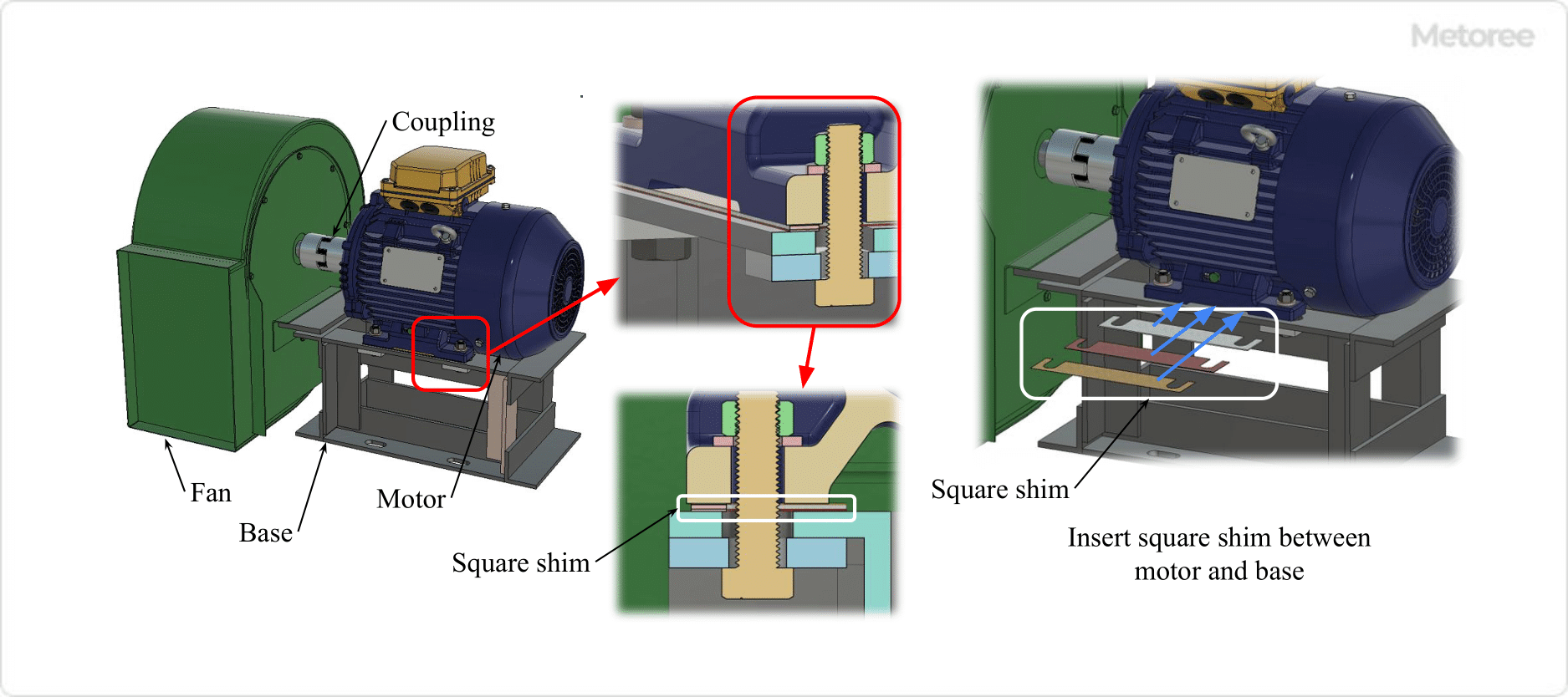
In the above example, a motor is used as a drive for a centrifugal fan. Angular shims (shims for the base) are inserted between the base on which the motor is installed and the motor mounting legs to adjust the tilt and level of the motor. As a result, the center of the motor output shaft – coupling – fan shaft is straight and accurate rotation is possible without vibration.

Spacers are also used to adjust gaps and spacing, but they are primarily used for adjusting the position of parts, not for adjusting the tilt and level. Liners are also used for the same purpose as shims, but with a thickness of t1.0 mm or more.

Principle of Square Shims

When high precision is required, simple installation of parts may not be enough to achieve the required accuracy. However, when the number of parts is large, it is not uncommon for the tolerance to accumulate and not be within the required accuracy after the entire assembly is completed.

Therefore, shim plates such as square shims are used for fine adjustment to ensure the required accuracy. The accuracy of the overall assembly is adjusted by inserting square shims between parts to change the tilt of the parts and the level of the parts.

The thickness of the square shim itself also requires accuracy and has a tolerance. It is important to check the thickness accuracy of the square shim to ensure that it meets the required accuracy. For the thickness accuracy, please refer to the dimensional table of each manufacturer.

Types of Corner Shims

1. Shape

Figure 2. Example of square shim geometry

Figure 2. Example of square shim geometry

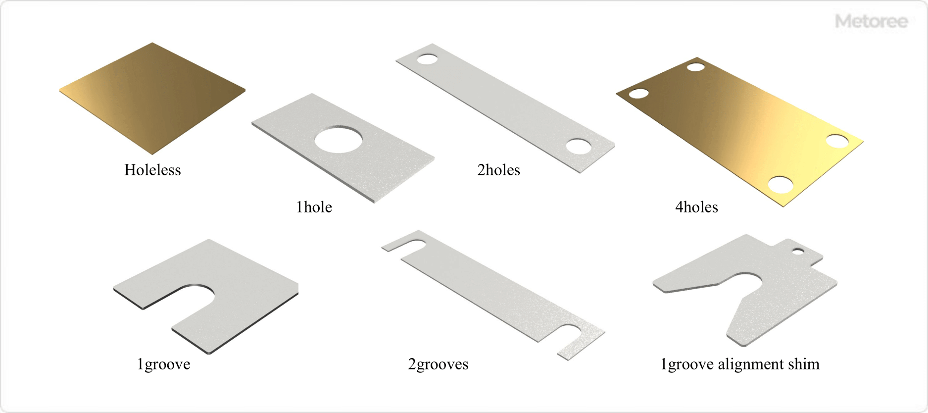
The main types of corner shim shapes are as follows:

  • Without mounting holes
  • With mounting holes (1, 2, 4 holes, etc.)
  • With mounting grooves (1, 2 groove, etc.)
  • Alignment Shims

Mounting holes and slots are mainly used for machines and equipment that are mounted and assembled with bolts. Slotted mounting holes allow insertion of bolts without completely removing them.

Alignment shims also have a portion to hook a tool or other object to facilitate insertion and withdrawal operations.

2. Material

Figure 3. Material example of square shim

Figure 3. Material example of square shim

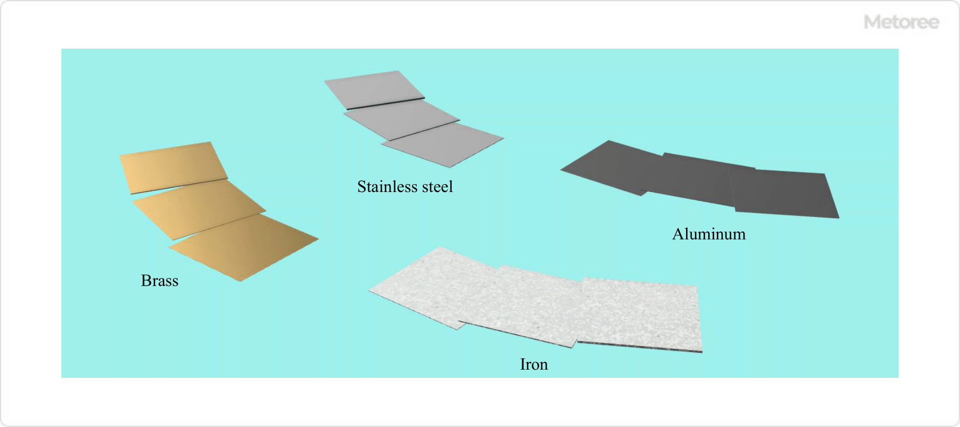
The following are the main types of materials used for square shims. For the selection of materials for square shims, stainless steel or aluminum is used if the environment in which they will be used, such as corrosion resistance.

  • Brass
    Brass C2680, C2681, etc.
  • Iron
    Cold-rolled steel sheet and strip SPCC, etc.
  • Stainless Steel
    Cold-rolled stainless steel sheet SUS304, SUS316, etc.
  • Aluminum (Al)
    Aluminum and aluminum alloy sheets and strips A1050

3. Other

Other types of angular shims include:

  • Surface Treatment
    Treated with black dye to prevent rust.
  • Adhesive Application
    Adhesive is applied to the surface for temporary fixing.
  • Laminate Type
    Several ultra-thin shim plates (e.g., t0.05 mm) are pre-bonded, and the thickness can be fine-tuned by peeling off one to several shim plates at a time.
  • Marking
    The surface is engraved and ink-marked with values such as plate thickness.
カテゴリー
category_usa

Carbide Ball End Mill

What Is a Carbide Ball End Mill?

Carbide Ball End Mills

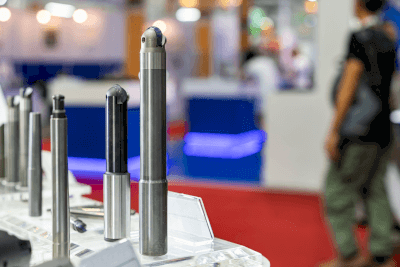
An everloy-cemented-carbide ball end mill is a cutting tool with a spherical cutting edge made of cemented carbide.

Cemented carbide, also called cemented carbide, is an extremely hard alloy. It is manufactured by adding tungsten carbide or titanium carbide to iron and pressing them together by powder sintering at high temperatures.

Ball end mills have cutting edges on the side and one end face, and the end face side is ball-shaped. Complex curved surface machining is possible. Carbide end mills are mainly used for machining center tools.

Uses of Carbide Ball End Mills

Ball end mills are suitable for cutting work to form curved surface shapes. In addition, they are also used for fillet sections to prevent parts and debris from accumulating in the bottom corners and for machining curved-shaped grooves as flow paths for liquids.

Specific applications include shape machining of molds, such as injection molds and lens molds, modeling, and small parts. The spherical tip of the cutting tool enables the machining of complex curved surfaces. However, it is not suitable for cutting work that requires sharp edges at the bottom corners.

Cutting with a ball end mill provides higher dimensional accuracy and more complex cutting work than plastic forming, such as press work.

Principle of Carbide Ball End Mills

Carbide ball end mills can machine curved surfaces using a ball-shaped cutting edge. Furthermore, when used in conjunction with NC machine tools, it is possible to machine complex three-dimensional curved surfaces.

Ball end mills do not have a large rigidity due to the small cross-sectional area of the cutting edge. Therefore, care must be taken to avoid spilling of the cutting edge. Cemented carbides for cutting tools are classified into three application categories: Class P, Class M, and Class K.

1. P-Type

Type P has excellent heat resistance and weldability, and contains a large amount of titanium carbide TiC and tantalum carbide TaC. This alloy is resistant to thermal damage, such as craters and thermal cracks. Its main applications are in the processing of steel, alloy steel, and stainless steel.

2. Type M

Type M contains moderate amounts of titanium carbide TiC, tantalum carbide TaC, etc., and is a strong alloy in terms of both thermal and mechanical damage. Its main applications are in the processing of stainless steel, cast iron, and ductile cast iron.

3. K Type

Class K is a tungsten carbide-WC alloy with excellent strength. It is particularly resistant to mechanical damage, such as crevice wear.

Its main applications are in the machining of cast iron, nonferrous metals, and non-metals. On the other hand, due to its hardness, it has a low stickiness and is easily broken. It is strong in compression, but weak against tensile and lateral forces.

Features of Carbide Ball End Mill

Advantages

  • Compared to press work and other shearing processes, cutting with end mills offers superior dimensional accuracy.
  • Unlike ordinary end mills, the rounded cutting edge enables the machining of complex curved surfaces by eliminating the edge portion. Curved surfaces can be freely formed as long as the radius of curvature is greater than the ball radius of a ball end mill.
  • With diamond coating, it is possible to machine carbide materials at an even higher level.
  • If the cutting edge wears out, it can be reground, making it economical.

Disadvantages

  • End milling results in a lower yield of material because there are more parts to be removed.
  • The machined surface is corrugated, which may cause surface variation. Therefore, machining takes longer because of the fill-in process.
  • Right-angle machining of the bottom corner is not possible. In addition, the discharge of cutting chips is poor.

Types of Carbide Ball End Mill

Carbide ball end mills are classified into three types in terms of structure: one-piece type, separate cutting edge type, and brazed type.

1. Integrated Type

The integral type is an end mill in which the shank and cutting edge are integrated into a single unit. Its high rigidity enables high-precision machining. Also, it can be re-grounded and re-coated for use even after wear.

2. Cutting Edge Separation Type

The cutting edge separation type is a type in which the cutting edge, called an insert, is fixed with a screw or a retainer. The price is reduced by partially using cemented carbide material. The feature of this type is that the cutting edge can be replaced with a new one when it is worn out.

3. Brazing Type

Brazed type is an end mill with a carbide blade brazed to the shank. This is a low-cost type.

カテゴリー
category_usa

Tilt Sensor

What Is a Tilt Sensor?

Tilt Sensors

A tilt sensor is a sensor that measures the inclination (tilt angle or slope) of an object.

Also called angle sensor, slope sensor, tilt sensor, or inclinometer. It is based on gravity and is installed horizontally to measure inclination.

Even when measuring in a vibrating environment, tilt sensors with additional electronics to adjust input and output can provide reliable measurement results due to the damping effect. Highly shock-resistant tilt sensors can measure acceleration in moving machinery, vehicles, aircraft, and construction equipment.

Uses of Tilt Sensors

Tilt sensors are used in a variety of uses, of which tilt adjustment is required.

  • Automotive Headlights
    Automatic adjustment of headlight beam angle.
  • Building Structure
    Detects tilting and other deterioration of building structures.
  • Work Truck
    Detects inclination of lifts, cranes, etc.
  • Transportation Equipment
    Detects tilting of transportation equipment in automobiles and railcars to prevent them from tipping over.
  • Workbench
    Maintain level forestry and construction equipment loading docks.
  • Correction of Industrial Machinery, Optical Devices and Inspection Equipment
    Corrects tilting of aircraft and construction equipment interiors, electronic balances, etc.
  • Smart Phone
    Automatic screen rotation.

Principle of Tilt Sensors

Tilt sensors are installed so that they are horizontal in the direction of measurement. There are two types of principles of tilt sensors: electrolytic and MEMS (Micro-Electro-Mechanical Systems). The MEMS type is the most common in terms of accuracy and response time.

1. Electrolyte Type (Capacitance Type)

Considering the fact that the surface of the liquid is horizontal, the tilt is detected as the amount of change in capacitance from the tilt of the liquid. A pair of electrodes is placed on the bottom of the device, and conductive liquid is enclosed in a cavity inside the device. When voltage is applied between the electrodes, an electric field is formed.

As the liquid flows, the electric field changes and the internal resistance of the circuit changes, and the angle is measured by measuring the amount of this change. However, care must be taken because the response time is relatively slow and the liquid level is easily affected by vibration.

2. MEMS Type

This method utilizes micro-electro-mechanical system technology. The inclination is measured by the deflection of the site due to gravity. Two pairs of fixed and movable electrodes are arranged.

The angle is measured by measuring the change in electrostatic capacitance from the change in the positional relationship of the electrodes due to inclination, and a low-pass filter is used to attenuate shocks to reduce errors.

Other Information on Tilt Sensor

Tilt Sensor and Acceleration Sensor

A tilt sensor detects the inclination (tilt angle or slope) of an object. There are also tilt sensors and acceleration sensors that can measure inclination.

1. Inclination Sensor
The sensor output itself contains the tilt angle information. Because of its low frequency fluctuation, the sensor is effective for measuring the tilt angle in slow motion or in a stationary state.

Since the tilt sensor detects tilting, it is effective in preventing cranes and construction vehicles, such as construction equipment, from tipping over.

2. Accelerometer
This sensor detects acceleration applied to an object. It detects not only the direction of gravity but also the forward/backward and left/right directions of motion. Compared to tilt sensors, these sensors have a wider frequency bandwidth and can measure fast movements.

Acceleration sensors are used in applications that change the vertical and horizontal display of a smartphone to match the environment in which it is used.

カテゴリー
category_usa

Mems Microphone

What Is a MEMS Microphone?

A MEMS microphone is a microphone that consists of MEMS components at the point of voice conversion.

MEMS microphone is an acronym for micro-electro-mechanical systems.

In the case of microphones, MEMS microphone plays the role of a transducer that converts sound waves into electrical signals by creating a diaphragm on a Si substrate using thin-film microfabrication technology. The MEMS device can also integrate ICs on the same substrate.

Uses of MEMS Microphones

Typical uses of MEMS microphone are microphones for smartphones. They are used not only in smartphones but also in a wide variety of audio and applications. They are also used in machinery, including biotechnology, medicine, and automobiles, and have attracted much attention in recent years.

With the recent rapid spread of smartphones and other electronic devices, microphone technology has also developed. In order to muffle noise and make calls in crowded places, electronic devices need to be equipped with multiple microphones.

This has led to a situation where MEMS microphones are attracting attention as a compact and high-performance alternative to conventional ECMs (electret condenser microphones).

Principle of MEMS Microphones

The principle of MEMS microphone is to detect the change in the capacitance value of the diaphragm, which is a MEMS element, when it is vibrated by sound waves, and to convert it into an electrical signal for output. The MEMS microphones are often amplified by the IC and handled as analog signal voltage/current values, or processed with digital signal processing (ADC) to perform highly efficient pulse width modulation (PWM) processing.

The MEMS microphone itself consists of a substrate covered by a cover, which has a single small hole to allow audio to enter the microphone and be detected by the MEMS element, MEMS microphones offer numerous advantages over conventional ECM microphones, including smaller size, higher heat resistance, reflow soldering capability, higher sound quality, improved reliability, longer battery life, and lower cost.

Applications where MEMS microphones are particularly well suited are those in environments with a lot of electrical noise. In environments where there is a lot of vibration, the relatively low output impedance of MEMS microphones and their superior noise rejection, combined with digital signal processing in integrated ICs, can reduce the harmful noise level caused by this mechanical vibration.

Other Information on MEMS Microphones

1. Comparison of ECM and MEMS Microphones

Compared to MEMS Microphones, ECMs are more difficult to use when mounted on high-density electronic devices because they are more difficult to miniaturize and reflow, etc. On the other hand, ECMs have many advantages that current MEMS microphones do not have, such as they have been used for a long time, they are available in a wide variety of types, so it is easy to utilize past design assets, they have a very wide range of specifications such as supply voltage range, and there are products with excellent sound directional characteristics. There are products with excellent sound directionality, which are not yet available with current MEMS microphones.

ECMs may be better suited for some applications than MEMS microphones, so it is important to choose the right one for your situation.

2. Examples of Application to AI Speakers

As of FY2022, many electronic devices, especially smartphones, are now equipped with numerous MEMS microphones. Until now, users have had little experience with the performance of MEMS microphones, and many users have not been aware of the fact that ECMs are being replaced by MEMS microphones in the market.

AI speakers, which have become a hot topic in recent years, requiring high-performance microphones, should benefit from MEMS microphones because they are directly linked to the quality of the user experience. In fact, a MEMS microphone that is cloud-free and capable of AI detection of several dozen keywords with an AI chip in the IC inside the MEMS microphone is being researched and developed by one manufacturer.

In the near future, it will not be too far off in the future when AI speakers that are commonly found in homes and cars will realize that their operation and sound quality are technologically supported by the high-performance technology of MEMS microphones.

カテゴリー
category_usa

Power Supply Module

https://us.metoree.com/categories/5276/What Is a Power Supply Module?

Power Supply Modules

A power supply module is the key component that provides an electronic device with the proper amount of power it needs.

It is responsible for converting the original power supply to the specific voltage or current required by the device. As a result, the device receives safe and efficient power. Power supply modules are generally purchased as components from specialized power supply module manufacturers, rather than designed in-house.

This approach has several advantages. First, it saves time and money. The quality of the power supply modules provided by the specialized manufacturer is guaranteed and has already been tested to a certain level of performance. Therefore, power supply solutions can be implemented more quickly and inexpensively than designing and testing power supply circuits in-house.

Furthermore, power supply modules can be applied to a wide range of electronic devices, such as servers, networking equipment, home appliances, and industrial equipment. Their form and performance will vary depending on the device used and its uses of, but their primary purpose is to regulate power properly and ensure proper device operation.

Uses of Power Supply Modules

Due to their versatility, power supply modules are used in a wide range of fields. The following are some specific examples of their use.

1. Computer System

In personal computers and servers, power supply modules play a major role. A computer consists of various components, such as the motherboard, CPU, memory, and storage devices, each of which operates at a specific voltage and current. Power supply modules provide adequate power to these components to ensure stable operation of the entire system.

2. Network Equipment

Network equipment, such as routers and switches, is another important use case for power supply modules. These devices transmit and receive data at high speeds, so a stable power supply is essential.

3. Industrial Equipment

Sophisticated equipment, such as CNC machines and robots, is used in the manufacturing industry. These devices also operate at specific voltages and currents and require power supply modules.

4. Medical Equipment

Medical devices require power supply modules that are safe and reliable because of their potential impact on the human body. For example, life-support devices such as artificial hearts and ventilators use power supply modules that can back up in the event of a power failure.

5. Home Appliances

Power supply modules are also used in home appliances such as televisions, washing machines, and refrigerators. These products obtain their power from the household power supply, and the power supply module converts that power into the form needed by the product.

Principle of Power Supply Modules

There are two types of power supply modules: switching power supply and linear power supply.

1. Switching Power Supply

Switching power supplies will control the current by turning the power supply on and off at a high frequency. Specifically, an AC power supply is first converted to DC using a rectifier. Next, this DC is converted into high-frequency pulse waves using switching elements, such as MOSFETs. This high-frequency pulse wave is then sent to a high-frequency transformer, which converts it to the required voltage.

PWM control adjusts the width of the pulse wave to maintain a constant output voltage. The voltage is generated as required by turning the switching elements on and off, and no extra power is consumed. In this way, switching power supplies achieves high efficiency. Therefore, they are often used in high-power applications, e.g., powering computers.

2. Linear Power Supply

Linear power supplies control the output voltage by directly regulating the current. This isolates the output from input voltage variations and provides a very smooth DC power supply. However, this method is less efficient and tends to generate heat. Linear power supplies are therefore used in areas where noise is not tolerated, such as in acoustic and precision measuring equipment.

Other Information on Power Supply Modules

About Noise

A problem with switching power supplies is the noise generated by high-speed switching. Since high-frequency noise can interfere with surrounding electronic equipment, noise countermeasures are important. Noise countermeasures include the use of ferrite cores and various types of EMI filters.

Thus, switching power supplies has made it possible to realize compact and highly efficient power supply modules, but the noise they generate must be carefully considered. Power supply design is optimized by considering the trade-off between the two.

カテゴリー
category_usa

Gland Packing

What Is Gland Packing?

Gland packing is a sealing material that is attached to the outer surface of a rotating or reciprocating shaft to seal the inside and outside of a machine or facility.

Gland packing is used for shaft sealing of shaft penetrations in machinery and equipment. Gland packing is defined as “a generic term for packing that is square or round in cross section and used for stuffing into stuffing boxes.”

Note that gland packing is not a perfect axial seal and is subject to some leakage. In pumps, however, leakage between the shaft and gland packing may be necessary to lubricate and cool the gland packing.

Principle of Gland Packings

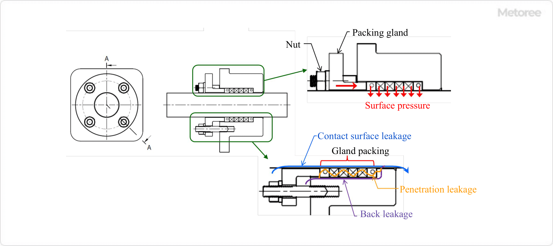
The gland packing principle of the gland packing is that the inner surface of the gland packing (shaft side) adheres to the outer surface of the shaft and the outer surface of the gland packing (housing side) adheres to the inner surface of the stuffing box, filling the gap between them and preventing fluid leakage by the contact surface pressure. 

Figure 1. Principle of gland packing

Figure 1. Principle of gland packing

The above surface pressure is caused by the gland packing being pushed by the packing gland (the part that holds the packing) when the nut is tightened, causing the gland packing to expand in the inner and outer radial directions. The more strongly the nut is tightened, the higher the surface pressure.

If the nut is tightened too much, the frictional resistance due to adhesion becomes too high, and a large load is placed on the rotating or reciprocating shaft. Care must be taken because this may interfere with the operation of the equipment. However, if the tightness is too weak, the fluid will easily leak.

There are three types of gland packing leakage, as described below. 

  • Leakage at contact surface. Leakage flowing between gland packing ID side and shaft OD side
  • Leakage at the back. Leakage flowing between the outer diameter side of the gland packing and the inner diameter side of the stuffing box
  • Seepage leakage. Leakage inside gland packing, mainly through the braided gaps in the braided packing

Uses of Gland Packing

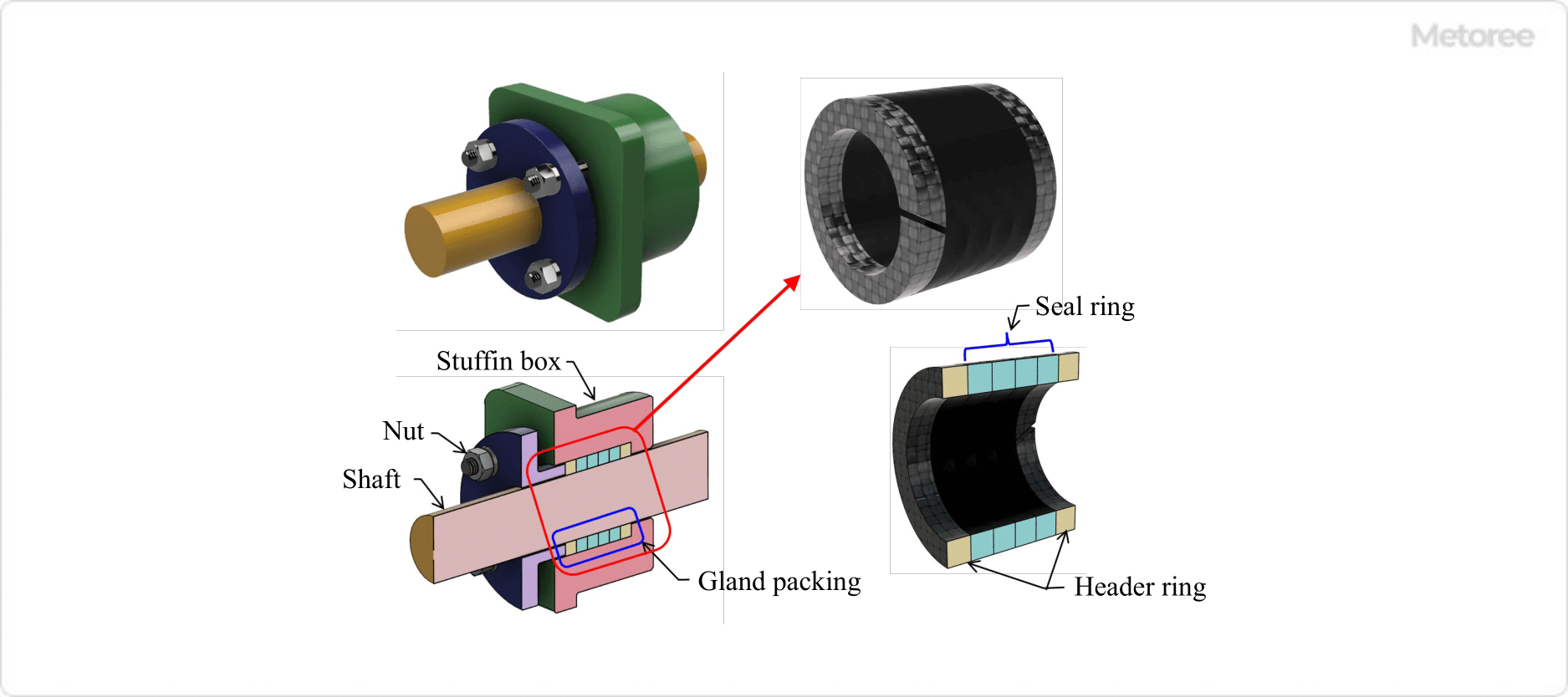
Figure 2. Example of gland packing use

Figure 2. Example of gland packing use

Gland packing is used in rotating or reciprocating machinery or equipment where the shaft protrudes externally through a housing or casing. These parts are used to prevent oil fluids, gases, and other gases inside the machine or equipment from leaking to the outside. 

Insert the gland packing into the housing or casing stuffing box (the box that contains the packing) so that it wraps around the outer circumference of the shaft at the shaft penetration area. Push the gland packing into place by tightening the nut at the packing gland (the part that holds and tightens the packing) so that the inside surface of the gland packing is more tightly pressed against the outside surface of the shaft.

Types of Gland Packing

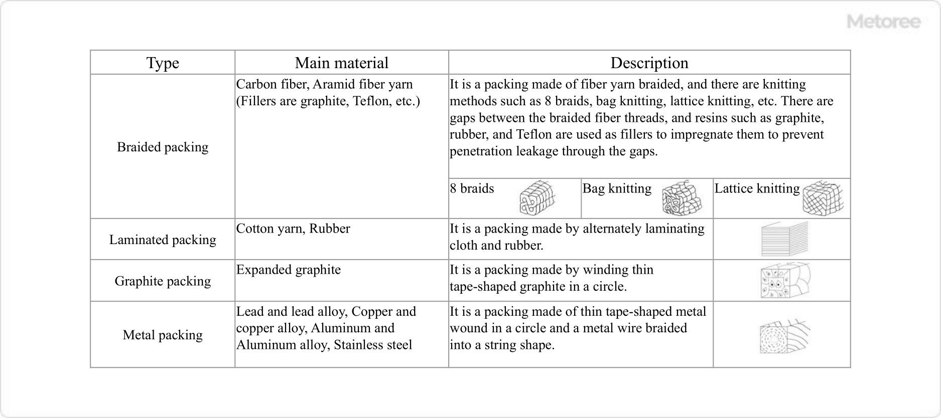
Figure 3. Types and main materials of gland packings

Figure 3. Types and main materials of gland packings

Gland packing is characterized by its relatively low cost as a shaft seal and simple structure compared with mechanical seals. Since each type has its own characteristics and the method of use and environment of use differ, it is important to check the manufacturer’s catalog, specifications, and instruction manuals before making a selection.

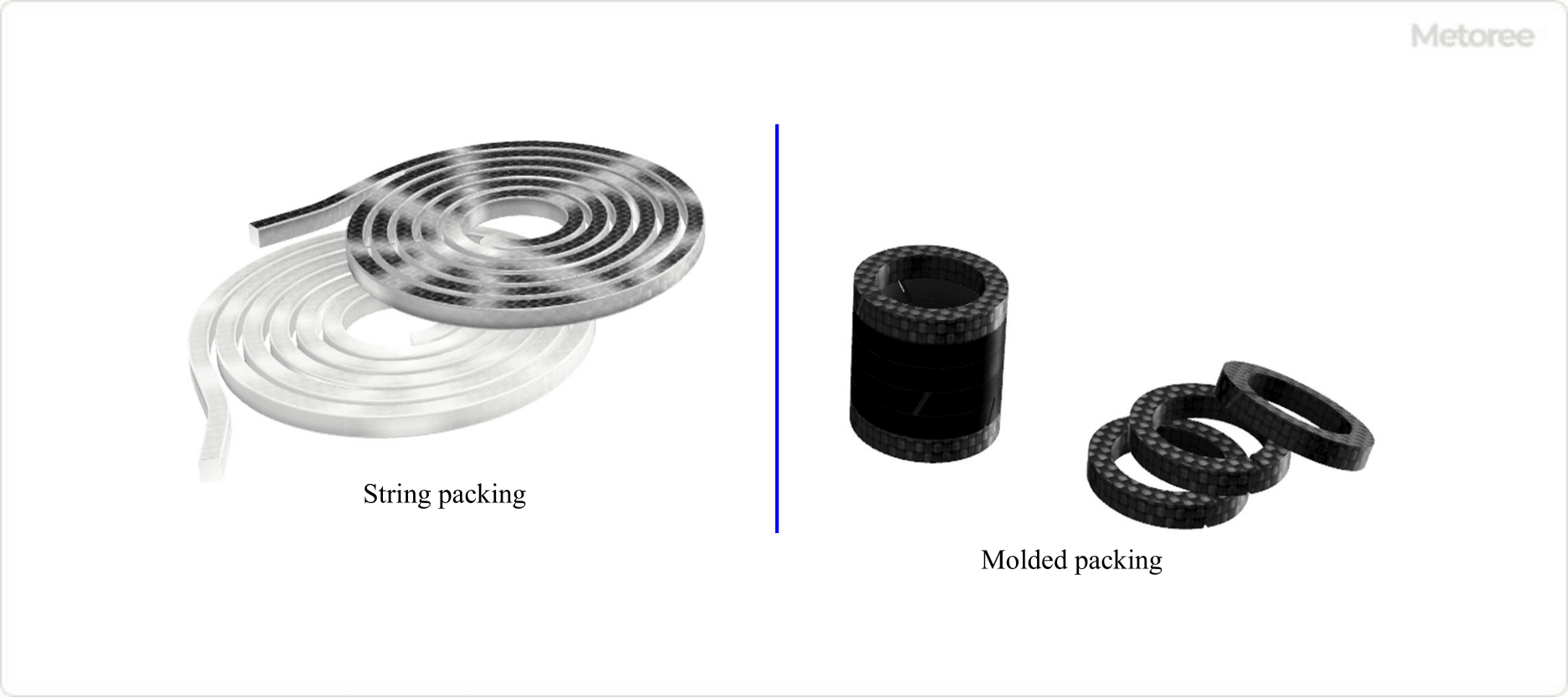
Figure 4. Types of gland packing

Figure 4. Types of gland packing

Gland packing (other than laminated packing) that is generally available on the market comes in a spiral wound form. Therefore, cut the packing to the required length according to the dimensions of the shaft and stuffing box, and insert it into the box. In addition to cutting and using the string packing, we can also produce a pre-molded ring-shaped packing to match the dimensions of the shaft and stuffing box.

The use of molded products improves the workability of packing insertion and sealing performance. In the past, asbestos packing (sealing material containing asbestos) was often used as a material for gland packing packings. 

Other Information on Gland Packing

1. Number of Gland Packing Used

Normally, one gland packing is not used alone, but several gland packings (in layers) are stacked. Also, as shown in the figure above, using several seal rings (sealing packings) in combination with header rings (overflow prevention packings) will provide a more secure seal.

The number of gland packing (number of steps), packing material, and pressure of the fluid to be sealed vary, so refer to the packing manufacturer’s product specifications or instruction manuals to determine the appropriate combination.

2. Direction of Motion of Gland Packing and Shaft

The uses of gland packing include the following, depending on the direction of the shaft motion.

For Rotary Motion Axis

Figure 5. For rotary motion shaft of pump

Figure 5. For rotary motion shaft of pump

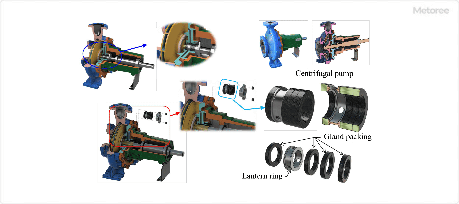
It is mainly used for shaft sealing of pumps, blowers, and other shafts.

For Reciprocating Shaft

Figure 6. For reciprocating shaft of valve

Figure 6. For reciprocating shaft of valve

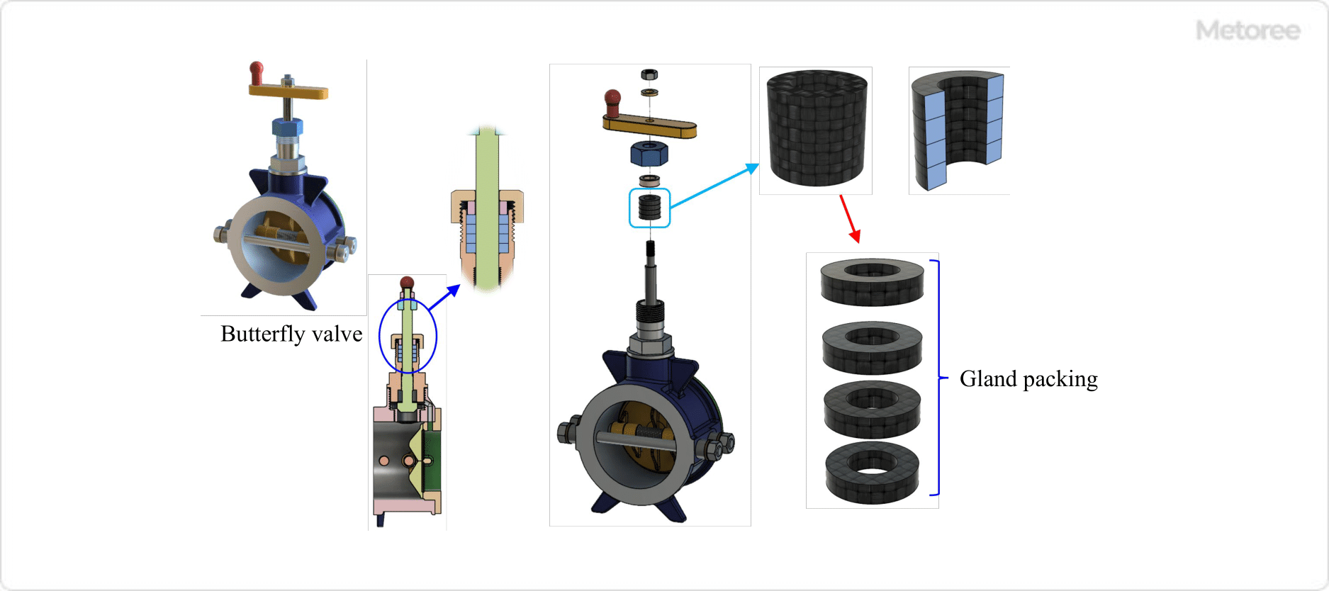
They are used for shaft seals of valve stems (valve rods) such as valves.

In addition to the above, they are also used in the shaft seals of various rotating machines and machines with reciprocating shafts. They seal liquids, gases, powders, and other substances to ensure the normal operation of machinery and equipment.

3. Combination of Gland Packing

The gland packing for the pump consists of three rings of braided packing and a lantern ring. This lantern ring is used for the following purposes:

  • Shaft cooling and lubrication
  • Prevents wear by draining sand and other contaminants from the gland packing when they are mixed in with the fluid.
  • Prevents air from being sucked in through gland packing when fluid pressure is below atmospheric pressure

Since gland packing causes some leakage, a shaft sealing device such as a mechanical seal is used when used to seal machinery, equipment, or hazardous materials with even less leakage.

4. Maintenance of Gland Packing

Gland packing may become worn and lose filler after long-term operation of the equipment, resulting in leakage. In such cases, the nut should be re-tightened or the gland packing should be replaced. Also, once a leakage path is created along the shaft, it is difficult to eliminate the leakage even by retightening, so replacement is also necessary in such cases.

カテゴリー
category_usa

Coating Equipment

What Is Coating Equipment?

Coating Equipment

Coating equipment is equipment for covering an object or surface with a specific substance.

Coating is the covering of the surface of an object with a material that can be fixed. In the food processing field, it is sometimes called coaching. The most suitable coating equipment is selected based on the shape of the object, the material, and the coating material. In the case of thin film coating equipment, we will consider whether it is small, large, for R&D, or for mass production, and in some cases, we will consider customizing the equipment by special order.

Uses of Coating Equipments

Coating equipment is used in a wide variety of fields, including automobiles, aircraft, precision equipment, metals, tableware, food, and medical products.

They are used for a variety of applications, including Teflon coating on frying pans and other food processing equipment, moisture-proof coating of electronic circuit boards in automobiles and aircraft, food processing coatings for confectionery, pet food, etc., and tablet coating for medicines.

Principle of Coating Equipments

Coating is a type of surface treatment and is a film forming technology that adheres a thin film to the surface of a product. Coating is also called vapor deposition processing. In vapor deposition processing, evaporation materials are evaporated and vaporized to form a thin film on the surface of a product.

In general, vapor deposition can increase surface strength, and can also add decorative, optical (reflective/transmissive), and functional properties to a product. Various types of vapor deposition materials are available, such as gold, silver, aluminum, chrome, and zirconia, which are vaporized and coated as a thin film on the surface of the product.

Type of Coating Equipment

There are various types of coatings depending on the object to be coated and the coating material, such as Teflon coating equipment for coating fluoropolymers, PR coating equipment for coating photoresist on copper foil, PVD coating equipment based on DLC diamond-like carbon films, food coating equipment for stirring and seasoning food, ICF coating equipment for coating true carbon films, and DLC coating equipment for coating diamond-like carbon films. ICF coating equipment, DLC coating equipment that uses diamond-like carbon films, and various other coatings depending on the object to be coated and the coating material.

1. DLC Equipment

DLC (Diamond-Like Carbon) coating equipment is a thin film of carbon with an amorphous structure (a film with diamond and graphite sp3/sp2 bonds). It can be coated in nano-level thinness and can add very high hardness and wear resistance to objects.

It is used to prolong the life of cutting tools, dies, punches, and various machine parts. The use of coated tools can also be expected to improve the finish and prevent welding in aluminum machining. The PVD (physical vapor deposition) method, which utilizes vaporization, does not require hydrogen for deposition.

Diamond-like carbon films are formed by decomposing C6H6 (benzene) in plasma using a special ion source in a vacuum. The plasma area is controlled by a multi-ion source and a substrate rotation mechanism to ensure uniform coating with strong adhesion, even on complex-shaped objects. It is characterized by high hardness (micro-Vickers hardness of 2,000 to 4,000), low coefficient of friction (μ = 0.2 or less), surface smoothness, and excellent resistance to welding and mold release, similar to diamond properties.

2. Fluidized Bed Coating Equipment for Food Processing

Coatings are used not only for chemicals and paints but also for food processing. Fluidized bed coating equipment is a coating equipment developed by applying the fluidized bed of a barrel polishing machine. The polishing technology of the polishing machine is applied to the coating technology.

The fluidized bed is sloped to allow for overflow, and various types of flow can be created. Uniform coating is possible in a short time, and high-quality food processing is possible with a few personnel.

3. Substrate Coating Equipment

Coating equipment used for coating substrates with moisture-proof insulating materials. The problem with conventional coating equipment is that it coats areas other than the base of the equipment. The substrate coating equipment does not require masking and the program automatically detects the area to be coated. Spraying the substrate enables efficient coating over a wide area or spot.

4. Titanium Nitride Coating Equipment

This coating equipment is often used for PVD coating. It is possible to achieve a well-balanced coating when adding hardness and heat resistance. It is particularly suited for coating tools and metals due to its excellent wear resistance. It has high adhesion and is sometimes used as a base coating for other ceramic materials.

It is important to note that the object must be thoroughly cleaned before coating. Dirt and rust generated from the surface can combine with the coating components, causing peeling, reduced adhesion, and discoloration. In addition, since the coating is applied in a high-temperature vacuum layer, resin materials must be handled with care.

Other Information on Coating Equipment

Features of Coating Equipment

The characteristics of vapor deposition processing are that it can be applied to a wide range of materials, including metals, nonferrous materials such as aluminum, and resins. Electroplating is a typical surface treatment that uses electric current to perform surface treatment, so even for non-conductive products such as aluminum and resin, vapor deposition can be performed without applying a load of electric current to the vapor-deposited material or product.

カテゴリー
category_usa

Roller Bearing

What Is a Roller Bearing?

Roller Bearings

A roller bearing is a type of rolling bearing that uses rollers as rolling elements.

The rolling elements are the parts of the bearing that rotate between the inner ring and outer ring (raceway) or raceways. Ball bearings are the most commonly used type of rolling bearing, but they differ significantly in that they use rollers (cylindrical parts) instead of balls as the rolling elements.

Roller bearings are used to support a rotating shaft that is subjected to heavy loads. The contact between the rolling elements and the inner and outer rings and raceways, as described below, is point contact in a ball bearing, whereas it is linear contact in a roller bearing. Since the contact area increases from a point to a line, a larger load can be supported.

Uses of Roller Bearings

Roller bearings are incorporated into a wide variety of industrial machinery. Specific applications include rotating parts in automobiles, rail vehicles, aircraft, construction machinery, wind turbines, and industrial robots.

Roller bearings can support higher loads than ball bearings and have higher support rigidity. On the other hand, ball bearings have an advantage in rotational performance. When a low load and high rotation is required, ball bearings offer lower rolling resistance. Because of these characteristics, ball bearings are often used in gearboxes of industrial machinery.

In automobiles and industrial machinery, helical gears are often used, where the gear teeth are aligned at an angle to the axis of rotation, resulting in lower noise and vibration. However, the oblique nature of the gears will result in large forces acting in three directions. Roller bearings are used to support these shafts.

Principle of Roller Bearings

There are two main types of roller bearings: radial roller bearings and thrust roller bearings. Each has a different structure, but the principle is the same.

The rollers roll between the two parts in which they are sandwiched, allowing the bearing to rotate smoothly while taking the large load generated on the rotating shaft. The surface of each part is finished to be hard and is less uneven, i.e., to have a small surface roughness. Heat-treated alloy steel is often used.

Structure of Roller Bearing

1. Radial Roller Bearing

It consists of an inner ring, outer ring, rollers, and retainer. The rollers are placed between the outer diameter face (raceway) of the inner ring and the inner diameter face (raceway) of the outer ring. Retainers are used to keep the rollers at an equal distance and to prevent excessive friction due to contact between the rollers.

2. Thrust Roller Bearing

The three parts are integrated, the rollers and retainers are integrated with one of the raceways, or all three are separate. The choice of integral or separate construction is determined by factors such as ease of assembly.

Types of Roller Bearings

There are several types of roller bearings, in addition to radial and thrust roller bearings. The two types are the open type, which is externally lubricated, and the sealed type, in which grease is sealed inside the bearing.

By keeping each rolling surface properly lubricated, the bearing continues to roll while an oil film exists on the outer diameter surface at each raceway. Therefore, even under high-load and high-speed operating conditions, frictional resistance is low and smooth operation for a long period is possible.

When classified according to the shape of the roller, they can be divided into the following four categories.

1. Cylindrical Roller Bearing

Cylindrical roller bearings have simple cylindrical rollers. Radial roller bearings support only radial loads, while in contrast, thrust roller bearings support only axial loads.

2. Needle Roller Bearings

A needle roller bearing is a roller bearing whose rollers are as long and narrow as a needle. Needle roller bearings are also called needle bearings. Although there are ISO specifications for this type of roller bearing, needle roller bearings are also referred to as bearings that fall outside the scope of these specifications.

3. Tapered Roller Bearings

Tapered roller bearings are mainly used as radial roller bearings. They are also called tapered roller bearings. Because the rolling elements are tapered, they can support loads perpendicular to the axis and axial loads in a fixed direction.

When used in two or more rows, it can support axial loads in either direction in the axial direction and can also take high moment loads. It is often used to support helical gears.

4. Spherical Roller Bearings

In spherical roller bearings, the rolling elements have a sag shape (cylindrical shape with a convex center). Furthermore, when the outer ring raceway is concave and the rollers are in alignment with the inner ring raceway, the circumference of the rolling elements is convex in line with the outer ring raceway.

Therefore, even if the center of rotation between the outer ring and inner ring is inclined, the inclination can be tolerated. It can support loads perpendicular to the shaft and axial loads in both directions.

Other Information About Roller Bearings

Precautions for Using Roller Bearings

Roller bearings are used especially for rotating shafts that must support large loads. When used, it is important to ensure sufficient rigidity in the inner and outer rings and raceways.

The bearing surface of the housing that supports these parts must also be sufficiently rigid. If the surface on which the rollers roll has low rigidity, the rollers will not make linear contact as designed and localized contact will occur. In such cases, the contact surface pressure will be high, and the life of the roller may reach its end earlier than expected in the design.

In addition, it is important to ensure sufficient lubrication, to ensure that the lubrication provides sufficient cooling effect, and to remove foreign matter such as iron powder from the operating environment, including lubricating oil, by means of oil filters or magnets.

カテゴリー
category_usa

Control Box

What Is a Control Box?

A control box, also known as a control panel or cabinet, houses circuits and devices for controlling electrical and mechanical equipment. These boxes protect their contents from environmental factors and reduce electric shock risks, ensuring operational safety. While similar in function to control panels, only boxes containing control equipment are typically referred to as control boxes.

Uses of Control Boxes

Control boxes are crucial for housing and protecting electronic devices, such as sensors and machine operation controllers. Their applications span various industries, including factory automation, elevator controls, and train operation systems. These boxes safeguard sensitive electronics from external shocks, dust, and other detrimental conditions.

Control Boxes Principle

Beyond protecting equipment, control boxes offer thermal protection, dust and waterproofing, and countermeasures against electromagnetic waves and corrosion. Features like cooling fans, slits for ventilation, and materials like stainless steel and polyurethane foam packing address these concerns, ensuring the longevity and reliability of the contained devices.

Types of Control Boxes

Control boxes vary in material and shape, catering to different operational needs:

1. Small Control Box

Designed for external installation, these boxes accommodate input devices like buttons and touch panels, allowing operators to control small devices conveniently.

2. Free-Standing Control Box

These self-supporting boxes are ideal for housing large control panels and equipment, with designs that offer high earthquake resistance for added safety and stability.

Other Information on Control Boxes

DIN Rail

Standardized DIN rails inside control boxes facilitate the mounting of control components like programmable logic controllers (PLCs) and electromagnetic relays. This system simplifies installation and maintenance, allowing for customizable layouts and efficient space utilization. Control components are often compatible with DIN rails, making it easier to design and construct systems as planned.