What Is an Incremental Encoder?
An encoder is a type of electronic component that uses a sensor to detect the amount, direction, and angle of mechanical movement and output them as electrical signals.
Encoders are divided into incremental encoders and absolute encoders, depending on the detection method.
An incremental encoder is an encoder that can measure the amount of change in position/rotation after the power is turned on. An absolute encoder can detect the absolute position/rotation from the origin even after the power is turned off.
With an incremental encoder, the absolute position cannot be determined unless a homing operation is performed after the power is turned off. The difference between incremental encoders and absolute encoders is whether this homing is required or not.
Uses of Incremental Encoders
Incremental encoders are used as position/speed detectors in various machines, including:
- Machine tools
- Semiconductor manufacturing equipment
- Mobile robots and automated guided vehicles
- Elevators
- Automobiles
Incremental encoders are often used as a component of motors. The encoder detects the direction and angle of rotation of a rotating shaft and uses the information for position and speed control of the motor.
Principle of Incremental Encoders
1. Incremental Encoder Method
Incremental encoders are divided into optical encoders and magnetic encoders, depending on the electrical detection principle.
- Optical Encoder
A light source such as LED is passed through a slit. The pulse of the light source passing through the slit is detected by a light-receiving element. This method is characterized by high accuracy and compatibility with high magnetic fields. - Magnetic Encoder
A permanent magnet is attached to the end of a rotating shaft. The magnetic field is detected by a Hall element and converted into a rotation angle. It is resistant to environments subject to vibration, shock, and dust.
2. Optical Incremental Encoder Configuration and Position Detection Principle
The position detection principle of incremental encoders is explained using an optical encoder as an example.
An optical encoder mainly consists of a light emitter, a light receiver, and a disc (scale).
The disc (scale) has a slit engraved on it. As the disc rotates, light emitted from the light emitter repeatedly passes through and is blocked by the slit, thereby generating light pulses on the photosensor. The number of pulses output corresponds to the amount of movement of the slit, and the amount of movement can be detected by the number of pulses counted.
The slit is engraved with three types of slits: phase-A, phase-B, and phase Z. The light-receiving element detects these three types of pulses.
- A-phase, B-phase
The number of slits determines the encoder’s resolution; the B-phase is offset from the A-phase by a quarter cycle (90°). - Phase Z
The number of rotations of the encoder can be counted by detecting the pulses of phase Z.
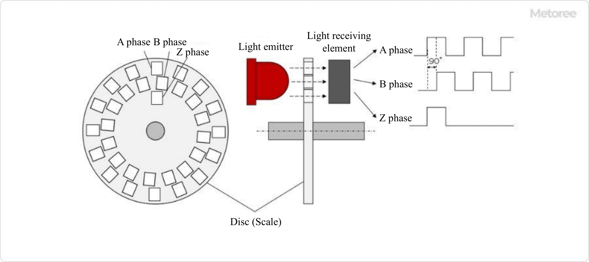
Figure 1. Optical incremental encoder configuration
There are two types of encoders: linear encoders, which detect linear movement, and rotary encoders, which detect rotational angles. Figure 1 uses a rotary encoder as an example, but the principle itself is the same for a linear encoder.
In a rotary encoder, slits are engraved on a disk-shaped disk, whereas in a linear encoder, slits are engraved on a rectangular-shaped scale like a ruler.
3. Principle of Detecting Direction of Rotation for Incremental Encoders
The rotational direction of FWD/REV can be detected by the order of the rising edges of the phase A and B pulses.
In FWD rotation, the rising edges of the phase A and B pulses are:
Phase A → Phase B → Phase A → Phase B → …
Phase A→Phase B→Phase A→Phase B→…
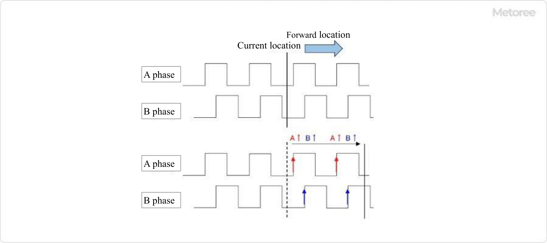
Figure 2. Detection order of phases A and B during forward rotation
In REV, the rising edges of the pulses of phases A and B are:
Phase B → Phase A → Phase B → Phase A → …
Phase B -> Phase A -> Phase B -> Phase A -> …
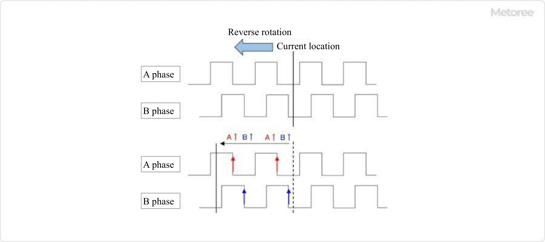
Figure 3. Detection order of phases A and B during reverse rotation
Since phases A and B are offset by 1/4 cycle, the direction of rotation can be determined by the order of the rising edges of the respective pulses.
Other Information on Incremental Encoders
Main Specifications of Incremental Encoders
The main specifications that can be used as an indicator when selecting an incremental encoder are as follows:
- Resolution
Number of pulses per revolution. - Power Supply
Power supply for encoder operation. - Output Signal Phase
There are two types: one that outputs phase A, B, and Z, and the other that outputs phase A and B. - Output Form
Pulse output form, such as open collector, line driver output, etc. Some encoders will output position via serial communication. - Allowable Speed
This is the upper rotational speed limit that the encoder can detect.