What Is a Safety Relay?
Safety relays are relays used to build safety circuits for machinery and equipment.
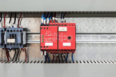
Safety Relays have a forced-guide contact structure and are used in the safety-related part of the control system to control the operation of machines only when safety is confirmed. This makes it possible to detect abnormalities and safely shut down equipment accordingly.
The “input section” receives the transmitted signal, determines whether the signal is safe or not, and sends the signal to the “output section. In the module, it plays a central role as the logic section.
Uses of Safety Relays
Safety Relays are mainly used to monitor safety functions. Examples are emergency stops, safety doors, safety mats, and other safety controls. They are designed to detect abnormalities in devices, sensors, or actuators and control them so that machines and equipment can be brought to a safe stop.
By incorporating modules that utilize Safety Relays, it is possible to ensure the safety of machines and equipment. They protect against hazards by detecting potential danger to operators, abnormalities in machinery and equipment, and potential damage.
Principle of Safety Relay
Safety Relays differ from ordinary relays in that they have a forced-guide contact structure with two types of contacts, a and b, each separated by a wall that must be insulated from the other. The b-contacts are interlocked according to the ON/OFF of the coil.
Additional Information on Safety Relays
1. Forced Guiding Contact Structure
The forced guiding contact structure is characterized by a structure that detects abnormal conditions when “if the a contact is welded, all b contacts have a contact gap of 0.5mm or more when the coil is OFF” and “if the b contact is welded, all a contacts have a contact gap of 0.5mm or more when the coil is ON. The structure is characterized by its ability to detect abnormal conditions when “all a-contacts have a contact gap of 0.5mm or more with the coil ON.
Therefore, the a-contact and b-contact are not in the same operating state at the time of contact welding. In the case of a system that controls ON/OFF of a machine, the structure is such that the a-contact is connected to the power control circuit and the b-contact to the monitoring circuit.
By doing so, when the a-contact is welded, the machine will only operate when the coil is in the ON state, and the machine will stop when it is in the OFF state. On the other hand, the b–contact is welded when the coil is in the OFF state, and works as a monitor to detect safety conditions.
2. Emergency Stop Pushbutton Switches
An example of a Safety Relay is an emergency stop pushbutton switch. This system has a safety function in which the contactor opens and closes the motor circuit upon actuation of the switch. If the emergency stop pushbutton is pressed while the motor is running, the motor stops immediately.
The emergency stop pushbutton switch uses NC (normally closed) contacts, which remain closed as long as the switch is not pressed. The system sends a safety signal during this time. When the emergency stop pushbutton switch is pressed, the contact opens and no safety signal is output.
The safety relay module detects the input of a safety signal from the emergency stop pushbutton switch and the pressing of the start switch of the control system, and outputs a signal to the contactor to allow motor operation.
If the safety signal from the emergency stop pushbutton switch is not input to the safety relay in this safety function system, the safety relay module stops outputting the signal to the contactor. This stops the motor.
3. Direct Circuit Operating Mechanism and Forced Guidance Mechanism
Relay circuit actuation mechanisms include the aforementioned forced guide mechanism and direct circuit actuation mechanism. The direct circuit operating mechanism is a mechanism that pulls the NC contacts of the safety switch apart by the force acting on the actuator when the contacts are welded together.
The forced guiding mechanism prevents the NO (normally open) contact and the NC contact from being turned on at the same time, and by monitoring one contact, it is possible to determine if the other is normal.
However, it is not possible to pull the contacts apart as in the direct circuit operating mechanism.