What Is an Earth Resistance Meter?
An Earth Resistance Meter is a device that measures the electrical resistance between an electrical device and the earth. It is one of the most familiar devices for electricians and electrical practitioners. Grounding refers to the connection between the earth and electrical equipment.
When an abnormality occurs in electrical equipment, a person touching the equipment may receive an electric shock. By grounding electrical equipment, it is possible to release the electric current to the earth in the event of an abnormality. Secure grounding is very important for the safety of electrical equipment. The state of being securely grounded is called “grounded.”
Uses of Earth Resistance Meters
Earth Resistance Meters are used for grounding work and electrical equipment inspections. Grounding is the process of burying a metal or other electrical conductor deep underground. It is one of the most important works for electricians, and is classified into four types from A to D according to the intended use of the grounding.
The grounding pole for high-voltage equipment is called Class A grounding, which must maintain a resistance of 10 Ω or less, and the grounding pole for low-voltage equipment of 100 to 200 V is called Class D grounding, which is specified as having a resistance of 100 Ω or less.
During grounding work, check the grounding resistance using an Earth Resistance Meter. Electricians and chief electrical engineers use Earth Resistance Meters on a daily basis.
Principle of the Earth Resistance Meters
The measurement principle of the Earth Resistance Meteris Ohm’s law. The Earth Resistance Meter applies an alternating voltage between the pole to be measured and the pole to be compared. After the voltage is applied, the current flowing between the two poles is measured, and the ground resistance is calculated by dividing the current by the applied voltage.
Although the above method can be used to calculate the ground resistance, this method measures the ground resistance of the target pole and the pole to be compared, plus the ground resistance of the two poles. Therefore, a separate grounding pole dedicated for voltage measurement is provided to measure the grounding resistance of the target pole only.
If a DC voltage is used in the Earth Resistance Meter, electrolysis occurs and the current value cannot be determined. Therefore, AC power is often used in Earth Resistance Meters. Since AC power supplies are affected by lead capacitance at higher frequencies, power supplies with a frequency of 1 kHz or lower are used.
How to Use an Earth Resistance Meter
There are three types of Earth Resistance Meters: analog display, digital display, and the method of reading the scale value when the scale needle displays “0”. As an example, the procedure for using an analog display type is shown below.
The Earth Resistance Meter comes with a metal rod called an auxiliary grounding pole, which is embedded in the ground when measuring earth resistance.
- Step 1: Embed the first auxiliary grounding pole P at a distance of about 10 m from the grounding pole to be measured (hereinafter referred to as “grounding pole E”).
- Step 2: Place an auxiliary grounding pole C at a distance of about another 10 meters on the straight line extension connecting the grounding pole E and the grounding pole P.
- Step 3: Connect each grounding pole to each terminal of the Earth Resistance Meter.
- Step 4: Confirm that the battery capacity is OK and that the voltage between E and P is less than the allowable value.
- Step 5: Press the measurement button, and the value displayed is the value of the grounding resistance.
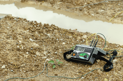
The procedure for other Earth Resistance Meters is basically the same as the analog display method, but the “read the scale value when the scale needle shows “0”” method reads the scale value when the scale needle shows “0”. The green, red, and yellow wires attached to the Earth Resistance Meter are used to connect each grounding pole to the terminals on the body of the Earth Resistance Meter.
In addition to these, there are also clamp-type Earth Resistance Meters that measure earth resistance by clamping the ground wire. It is easy to measure because there is no need to bury the auxiliary pole in the ground, but it can be used only in the case of multiple grounding.
Other Information on Earth Resistance Meters
Difference Between an Earth Resistance Meter and an Insulation Resistance Meter
Insulation testers and Earth Resistance Meters differ in measurement items and objects to be measured. An insulation tester measures an electric circuit to check the insulation status, while a grounding tester measures the grounding pole to check the grounding resistance.
The insulation tester applies a DC voltage, while the Earth Resistance Meter applies an AC voltage. Although the appearance and names of the devices themselves are similar, it is important to understand the above-mentioned differences between them in advance.