What Is a High Voltage Probe?
High voltage probes are passive probes capable of measuring high voltages.
In high voltage measurements that exceed several hundred volts, standard voltage probes will break down and cannot be used. General-purpose probes have difficulty handling high frequencies and high voltages. In contrast, high voltage probes can measure voltages as high as several thousand to several tens of thousands of volts and are passive probes dedicated to high voltages.
High voltage probes are used, for example, when measuring voltage waveforms by connecting them to an oscilloscope or other dedicated measuring instrument. When measuring large voltages at high frequencies, the probes quickly heat up, so care must be taken to avoid burns or electric shock.
Uses of High Voltage Probes
High voltage probes are used to measure waveforms of high voltages of several hundred volts or more, and are often used to measure signals in motor drivers, switching power supplies, inverters, and converters that use power devices such as IGBTs (insulated gate bipolar transistors).
They are also often used in DC circuits and other situations where high voltage loads are possible. Other applications include measuring the anode voltage of cathode ray tubes as well as safety inspections of photovoltaic power generation equipment such as mega solar power plants without interrupting the grid, and measurements of high-voltage electrical systems used in hybrid and electric vehicles.
When selecting a probe, consider the frequency bandwidth, input resistance, input capacitance, operating voltage range, and compatible oscilloscope model.
Principle of High Voltage Probes
High voltage probes measure high voltages by dividing them by the ratio between the internal resistance of the oscilloscope or other measurement device and the probe’s magnification resistance. When measuring high voltages, a high voltage probe with an attenuation ratio of 100:1 or 1,000:1 is used.
The probe is used to physically and electrically connect the test point, or signal source, to the oscilloscope. The maximum allowable voltage of the voltage probe must be checked for rating due to its tendency to decrease with increasing frequency.
Specifically, the probe is placed between the input terminal and the oscilloscope input section, and the waveform passing through it is measured. When measuring high-frequency signals, the input capacitance becomes a load and affects the signal. However, by connecting through a probe with a high attenuation ratio, a more accurate waveform can be measured.
Structure of a High Voltage Probe
The construction of high-voltage probes varies depending on the voltage range to be measured. Products with a DC voltage of about 25KV sold by oscilloscope manufacturers can be handled by the user in the same way as general probes.
A high voltage probe consists of a probe body, a matching box, and a cable connecting them. The inside of the probe is filled with insulating oil or gas to enhance withstand voltage performance. The input resistance of the probe body depends on the attenuation of the attenuator, but a large value of 100 to 1,500MΩ is used.
The matching box performs phase compensation, and the adjustment procedure is more complicated than for ordinary passive probes because of the large attenuation of the attenuator and the use of long cables. In some cases, manufacturers of high voltage probes ship them adjusted and forbid the user to adjust them.
Other Information on High Voltage Probes
1. Safety Precautions for High Voltage Probes
Since high-voltage probes handle high voltages, various safety measures are taken, such as the following:
- Long cables (3m to 10m) are available so that the system under test can be measured from a distance because of the high voltages.
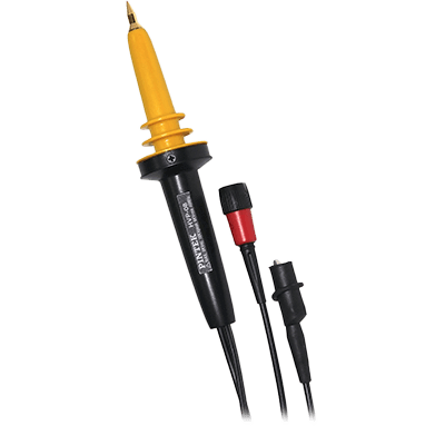
- Probes designed for hand-held operation are equipped with a large guard ring to prevent discharge to the human body. In addition, the probe body, which is designed to be fixed, has a terminal for grounding the probe itself.
- Handling precautions are also important. For example, when measuring high-frequency voltages, the higher the frequency, the lower the allowable voltage of the probe, so the manufacturer’s characteristic diagram must be fully understood. Also, if the ground terminal of the probe is disconnected, high voltage will be applied to the input terminal and the enclosure, which is dangerous.
2. Isolation Probe
An isolated probe is one in which only the probe is floating. It is electrically isolated from the oscilloscope body.
There are two ways to isolate the probe: one is to use a transformer to separate the probe tip from the oscilloscope, and the other is to convert the electrical signals received at the probe tip to photoelectric signals, transmit them through an optical fiber, and return them to the original signals at the receiver side. In both cases, there is no electrical continuity between the probe and oscilloscope. They are insulated from each other, but the signal detected by the probe is transmitted to the oscilloscope side.
Because of this configuration, even though the oscilloscope itself is properly grounded, it has no effect on the signal of the circuit under test that is applied between the tip of the isolated probe and the ground lead. Thus, even if the circuit under test has a very high common-mode voltage, the isolation probe can be used to measure only the differential voltage between the tip and ground lead.