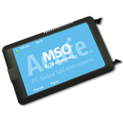
What Is a Logic Analyzer?
 A logic analyzer is a device primarily used to verify the operation of digital circuits.
They are sometimes compared to oscilloscopes, which are mainly used for analyzing analog signals.
Uses of Logic Analyzers
Logic analyzers are essential tools for verifying and troubleshooting digital circuits and are used in product development and manufacturing.
For multiple signal inputs, analog characteristics are not measured, but converted to 0s and 1s using threshold values for further processing. Since signals are treated as digital data, logic analyzers are used in the following applications:
- Debugging and verification of system operations.
- Simultaneous tracking and correlation of multiple digital signals.
- Detection of timing violations and transients on buses.
- Tracing the execution of embedded software.
Logic Analyzer Principles
A probe is connected to the measurement point of the system under test (SUT) and the signal is transmitted to the logic analyzer, first passing through the internal comparator.
The comparator compares the signal to a threshold voltage set by the user, and if the measured voltage exceeds that of the threshold voltage, the signal is transmitted to the next stage as a 1; if the voltage is lower than the threshold voltage, the signal is transmitted as a 0. In other words, after passing through the comparator, the signal is treated as digital.
The result is output as a digital signal corresponding to the clock and trigger conditions. The clock can be either the internal sampling clock of the logic analyzer or the SUT’s clock, depending on the application.
The former is done to obtain timing information between each signal, and the latter to obtain state. Trigger conditions can be set for various items such as specific logic patterns, number of events, and event duration.
It is important to set appropriate threshold values based on the signal level of the circuit being tested, and to set appropriate clock and trigger conditions for the information to be obtained.
How to Use the Logic Analyzer
Connect the probe to the SUT and set names for individual input signals. When measuring multiple signals such as buses, it is easier to observe the measurement results if they are grouped and registered.
Next, determine the sampling time. The higher the sampling clock frequency, the more detailed the signal measurements become. On the other hand, the amount of data that can be captured is constant, so the time range that can be observed becomes narrower. The signal sampling interval can be obtained from the following equation.
Sampling interval (sec) = 1/frequency (Hz)
Finally, set trigger conditions. In addition to defining triggers, the display method for when a trigger occurs can be specified. This allows you to specify whether to stop sampling after a trigger occurs once or to update the results each time a trigger occurs.
Other Information on Logic Analyzer
1. The Difference Between a Logic Analyzer and an Oscilloscope
While oscilloscopes can observe analog characteristics such as signal waveforms, logic analyzers handle digital data from signals.
Although oscilloscopes provide more information from a single signal, they can only observe about four signals simultaneously, whereas logic analyzers can handle many input signals at the same time.
2. Points to Note When Using a Logic Analyzer
There are a few precautions to take when using a logic analyzer to prevent damage to the SUT or logic analyzer itself and to obtain accurate measurements.
Make sure the SUT is turned off.
When connecting a probe to the SUT, there is a risk of contact between the measurement point and its surroundings via the probe; if the SUT is powered, a large current may flow at that moment and cause failure. Therefore, the SUT should only be turned on after the probe is connected.
Select the probe appropriate for your application.
There are three types of probes:
- Flying-lead probes connect a separate lead to each signal to be measured.
- Connector probes connect to a connector dedicated to the logic analyzer.
- Connectorless probes connect directly to the footprint of the board.
Select the probe that best suits your application.
Set the measurement conditions according to the application.
Set the sampling clock and recording time according to the frequency of change of the signal to be measured and the measurement range. Depending on the performance of the logic analyzer, select the settings and model to obtain correct measurement results based on the resolution and memory capacity.