カテゴリー
category_usa

Helical Gear

What Is a Helical Gear?

A gear is a toothed wheel designed to transmit torque through meshing with other gears. Helical gears, a common type of gear, have teeth cut at an angle, forming a helix.

Unlike spur gears that only transmit power with parallel axes, helical gears can also operate with intersecting axes. Their teeth are arranged diagonally, allowing for smoother meshing and continuous contact between teeth. This design reduces noise and vibration during operation but makes the manufacturing process more complex.

Uses of Helical Gears

Helical gears are widely used in several industries due to their efficiency and smooth operation:

1. Automobiles

In automobile gearboxes, helical gears transmit power from the engine to the wheels. They facilitate different gear ratios for various speed ranges, contributing to smooth gear changes and quiet operation.

2. Industrial Machinery

These gears are integral to many industrial machines, driving conveyor belts, and axis drives in CNC machines, ensuring precision and reliability.

3. Aircraft

Helical gears in aircraft transmit power in engine mechanisms and control systems, ensuring efficient motion transfer to propellers or fans and reliable operation in control systems.

4. Generators

Used in generators and turbines, helical gears transfer high-speed rotational power, playing a crucial role in effective power generation.

Principle of Helical Gears

Helical gears work by meshing teeth cut in a helical pattern, providing a high meshing ratio for smooth and continuous engagement. The progressive contact of the teeth distributes force evenly, reducing sudden stress and ensuring smoother power transmission.

The helical design creates thrust forces during rotation, necessitating robust bearings to withstand these forces. Angular contact bearings are common, but thrust bearings may be used for heavy loads.

Choosing Helical Gears

The helix of helical gears can be either right-handed or left-handed. The selection depends on the alignment of the input and output shafts. For parallel shafts, gears with the same helix direction are used, while intersecting or helically aligned shafts require opposite helix directions.

The helical angle, representing the axial advance per revolution, is crucial. A larger helical angle results in smoother gear meshing and quieter operation. Careful consideration of the rotation direction and helical angle is essential to ensure efficient power transmission and gear longevity.
カテゴリー
category_usa

Power Breaker

What Is a Power Breaker?

A power breaker, commonly referred to simply as a breaker, is an essential component in electrical systems. It is used to connect power lines to electrical machinery, typically through a power distribution or control panel. The connection from the breaker to the machinery is often made using components like electromagnetic contactors.

Power breakers are vital not only in industrial settings but also in residential environments.

Uses of Power Breakers

Power breakers are crucial for protecting equipment and preventing fires by interrupting the power supply in cases of overcurrent. This function is essential when connecting devices like plugs or operating power-driven machinery.

There are two main types of power breakers: wiring breakers and leakage breakers. Wiring breakers, also known as safety breakers, cut off the power supply when the current exceeds a set limit. Leakage breakers perform a similar function but also detect and interrupt power leakage from equipment or wiring.

Principle of Power Breakers

The capacity of a breaker is indicated by its Ampere Frame (AF), which also determines the size and interrupting capacity. The rated current is represented by Ampere Trip (AT), denoting the current level at which the breaker will trip. AF indicates the maximum current a breaker can handle, while AT specifies the tripping threshold.

Breakers can trip based on three different mechanisms. The first is thermal-magnetic, utilizing a bimetal strip that bends when heated by overcurrent, triggering a trip. The second is electromagnetic, where an electromagnetic force generated by overcurrent overcomes a spring, causing the breaker to trip. The third type is electronic, employing circuitry to detect overcurrent and activate the tripping mechanism.

カテゴリー
category_usa

Simple Cart

What Is a Simple Cart?

A simple cart is a versatile tool for storing, displaying, and transporting goods. This term encompasses various vehicles and structures like carts, wagons, racks, and cargo carriers.

Carts are designed for item transportation and are often foldable for convenient storage. Wagons, available in multiple sizes, are suitable for carrying a range of item sizes and can be used for both transportation and product display. Racks typically feature a mesh or wire structure, while cargo carriers are ideal for moving large or bulk items.

Uses of Simple Carts

Simple carts, including cargo carriers, are widely used for transporting large items. These carts can be easily loaded onto trucks for transport. Available in various sizes, they cater to both commercial and personal needs. Lightweight carts are particularly useful for everyday tasks like grocery shopping or transporting heavy items like beverage cases.

In shopping centers, carts are often two-tiered to securely hold baskets and prevent them from tipping over. Some models also include features for safely carrying small children.

Principle of Simple Carts

The design of simple carts focuses on efficient transportation of goods. Many feature casters for easy movement and are constructed with high-strength materials for durability. Shopping carts are specifically designed to hold a standard 33 L basket and often have minimal structural elements to maximize strength and basket capacity.

Household carts emphasize storage convenience and are frequently foldable for space-saving storage. To protect fragile items during transport, these carts often have casters made of shock-absorbing materials like rubber. Household racks come in various sizes, from compact models for specific spaces to adjustable designs for customizable storage solutions.

カテゴリー
category_usa

Shunt Resistor

What Is a Shunt Resistor?

A shunt resistor is a component used to measure current in an electrical circuit.

The term “shunt” implies meanings such as “diverting” or “sidetracking,” leading to its alternative name, “current shunt.” This component is primarily used for current verification, battery level detection, and similar applications. It offers a reliable method for measuring electric current.

As current passes through the shunt resistor, its resistance value and the voltage drop across it are used to accurately determine the current. A notable feature of shunt resistors is their applicability in high-current situations.

In high-current circuits, where wires are often thick, traditional clamp-type current measurement methods can be challenging. Using a low-resistance shunt resistor, accurate and reliable current readings can be obtained. However, in high-current circuits, shunt resistors may generate significant heat, necessitating cooling solutions.

Uses of Shunt Resistors

Shunt resistors are utilized in various electrical circuit applications, as outlined below:

1. Instrumentation Wiring

Commonly, shunt resistors have a resistance value of 250Ω. The DC4-20mA current signal is a standard analog output signal, less affected by a voltage drop due to its nature as a current signal, hence its widespread use.

Conversely, DC1-5V voltage signals are often used as input signals. To convert a DC4-20mA signal to a DC1-5V voltage signal, a 250Ω resistor is connected in parallel to the input terminal.

2. Power Electronics

In power electronic devices like inverters, current control and monitoring are essential. Shunt resistors are used for controlling and detecting overcurrent. In inverters, they manage the current on the DC side and regulate the output on the AC side.

Also, in industrial rectifiers, shunt resistors are commonly used for current measurement. These rectifiers supply direct current to trains, electrolytic cells, plating tanks, etc., where currents can reach tens of thousands of amperes. Shunt resistors capable of handling these high currents are therefore essential.

3. Electric Vehicles

In electric vehicles, shunt resistors are used for current control, regulating power flow from the battery to the motor and limiting current during rapid charging to protect the battery.

Principle of Shunt Resistors

The fundamental principle of shunt resistors is based on Ohm’s Law, which states that the current (I) flowing through a resistor is proportional to the voltage (V) across it divided by its resistance (R).

Shunt resistors are typically connected in series with the circuit carrying the current to be measured. The same current flows through the shunt resistor. With its known resistance, the current can be calculated by measuring the voltage drop across it with instruments like a voltmeter.

Types of Shunt Resistors

There are various types of shunt resistors, including:

1. Wire Type Shunt Resistor

This common type uses a high-resistance metal wire, thin and wound into a coil, to achieve low resistance. It is versatile and suitable for a wide range of current values, from low to high.

2. Strip Shunt Resistor

Strip shunt resistors use a flat metal strip. Like wire-type resistors, they have low resistance and can handle high currents. They are particularly efficient in heat dissipation, enabling stable operation under high-load conditions.

3. Metal Film Shunt Resistor

Made with a metal film, these resistors involve a metal film deposited on a substrate to form the resistance pattern. Metal film shunt resistors are known for their high accuracy and stability, maintaining consistent performance even with temperature fluctuations.

カテゴリー
category_usa

Diamond Cutter

What Is a Diamond Cutter?

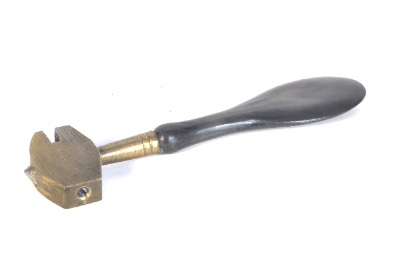
Diamond Cutter

A diamond cutter is a cutting tool designed for the precision cutting of hard materials without the need for traditional grindstones or blades.

It features a disc-shaped design embedded with diamond particles on its cutting edge. Diamond cutters are primarily used for cutting a wide range of materials including stone, ceramics, glass, alloys, and plastics. These cutters are known for their exceptionally sharp edges, enabling high-precision cutting. They offer remarkable durability and rapid cutting speeds. Due to their cutting mechanism, which involves grinding away material, they are often more efficient compared to conventional grindstones or blades. However, it’s essential to employ proper cooling methods when using diamond cutters due to the sensitivity of diamonds to heat.

Uses of Diamond Cutter

  1. Stone Cutting
    Diamond cutters are widely employed for cutting stones such as marble, granite, limestone, and more.
  2. Ceramics Cutting
    They are used for precision cutting of ceramics, including pottery, tiles, and porcelain.
  3. Glass Cutting
    Diamond cutters are essential for cutting glass materials such as sheet glass, mirrors, and glass tubes.
  4. Alloys Cutting
    They are used in cutting alloys like stainless steel, aluminum, copper, and more.
  5. Plastics Cutting
    Diamond cutters are employed for cutting plastics such as ABS resin, polycarbonate, polyacetal, and others.
  6. Semiconductors Cutting
    They play a crucial role in cutting semiconductor materials like silicon wafers with precision.

Features of Diamond Cutter

Advantages

Diamond cutters offer numerous advantages for cutting hard materials:

  • Ability to cut extremely hard materials that are challenging or impossible to cut with conventional tools due to the exceptional hardness of diamonds.
  • High strength, outstanding durability, and minimal wear and deformation even during extended use.
  • Efficient heat dissipation during high-speed cutting, preventing overheating due to the high thermal conductivity of diamonds.
  • Exceptionally hard and durable cutting edges coated with diamond powder, allowing for high-precision cutting.

Disadvantages

However, diamond cutters also have some drawbacks:

  • Higher manufacturing costs due to the need for expensive materials, as diamonds are exceptionally hard and wear-resistant.
  • Susceptibility to chipping or cracking if subjected to impacts or drops due to the brittleness of diamonds, requiring careful handling.

Types of Diamond Cutters

Diamond cutters come in various types based on their shapes, including:

1. Segmented Type

This type is suitable for cutting hard materials like concrete and asphalt. It consists of segments embedded with diamond particles around the cutter’s edge.

2. Rim Type

Used for precision work on materials like ceramics and glass, the rim type features a single row of diamond particles around the cutter, resulting in a smooth cut surface finish.

3. Turbo Type

Combining characteristics of segmented and rim types, the turbo type provides fast cutting speeds with minimal marks on the cut surface. It is commonly used for cutting ceramics, stone, and concrete.

4. Flat Type

Featuring a flat metal plate coated with diamond particles, the flat type is primarily used for cutting softer materials like rebar. It is typically attached to power tools such as circular saws and hand cutters.

How to Use a Diamond Cutter

The process of using a diamond cutter for material cutting involves several steps:

1. Preparation

  • Secure the material to be cut.
  • Attach the diamond cutter to the cutting device.
  • Adjust parameters such as rotation speed, feed rate, and coolant supply as needed.

2. Start Cutting

  • Bring the diamond cutter into contact with the material.
  • Initiate the cutting process, ensuring that the cutter rotates at an appropriate angle to the cutting surface.
  • Gradually press the rotating cutter into the material.

3. Progressive Cutting

  • Advance the diamond cutter along the material, adjusting cutting conditions as necessary.
  • Ensure proper coolant supply to extend the life of the diamond cutter and achieve a smooth cut surface.

4. Completion of Cutting

Finish the cut, removing any cutting debris or dust generated during the process.

5. Finish the Cut Surface

If required, use appropriate tools to smooth the cut surface.

Other Information on Diamond Cutter

1. Classification Based on Usage Environment

There are two types of diamond cutters based on their usage environment:

Wet Diamond Cutter: Utilizes water for cooling during cutting, minimizing dust dispersion, and ensuring high-quality cutting of hard materials like stone, tiles, ceramics, and concrete.

Dry Diamond Cutter: Cuts materials without the use of water. While it may result in more dust and a rougher cut surface compared to wet cutters, it is suitable for portable power tools and indoor use, commonly used for cutting softer materials like wood, plastic, and metal.

誘電体

誘電体とは

誘電体とは、電気的に非導電性の物質または材料です。

電気絶縁体とも呼ばれ、導電しないため絶縁物として使用されます。電子回路や電力伝送線路などにおいて、回路同士を絶縁したり、電気的なショートや漏電を防ぐことができます。電気による火災事故や漏電による感電事故を防止するための重要な材料です。

また、誘電体は高い誘電率を有するため、電場中で電場エネルギーを蓄積することが可能です。キャパシタの間に挟みこんで使用します。これにより、キャパシタの蓄電性能を向上させる上で有利です。

誘電体の使用用途

誘電体は絶縁性や電場への応答性などから、様々な用途で広く使用されます。以下はその使用用途一例です。

1. コンデンサ

コンデンサは電子回路で電荷を蓄積するデバイスであり、誘電体はコンデンサの絶縁材料として使用されます。誘電体がコンデンサ内部に挿入されることで、電場中で電気的な双極子が生成され、電荷を貯蔵することが可能です。コンデンサの容量を増加させ、電荷貯蔵能力を向上させる上で役立ちます。

様々な場面でコンデンサが活躍します。例えば、カメラのフラッシュ充電や、電源供給回路の安定化、信号処理などの電子回路処理においてもなくてはならない装置です。

2. 高電圧送電回路

誘電体は高電圧環境での絶縁材料として使用されます。高電圧変圧器や変電所の絶縁物として誘電体が使用され、送電網において電力を伝送する際の安全性を確保します。碍子や硬質樹脂などの耐久性の高い誘電体を使用することが一般的です。

3. 静電容量式センサー

静電容量式センサーは誘電体を含むコンデンサを使用して、物体の位置や状態を検出および測定するセンサーです。物体がセンサーに近づくと、センサー間の静電容量が変化し、物体の存在や位置を特定します。触れずに物体を検出する非接触検知に適しています。

4. 医療機器

医療機器において、誘電体は電気的な絶縁材料として使用されます。一例として、MRI (磁気共鳴画像診断) 装置では、患者への高電圧パルスを安全に伝えるための絶縁材料として誘電体が使用されます。患者の安全性と診断の正確性を確保するために不可欠です。

誘電体の原理

空気や真空などの非導電性媒体と比較しても、高い誘電率を有する点が誘電体の特徴です。誘電率は通常ε (イプシロン) と表され、物質の電場内での電気的な応答能力を示す指標です。誘電率は真空または空気の誘電率を基準として表され、高いほど、電場に対する応答が強くなります。

誘電率が高い誘電体は電場中で電荷を蓄積し、電場エネルギーを蓄積することが可能です。これにより、コンデンサの容量を増加させたり、電場中での電子の移動を制限したりします。

誘電体が外部の電場にさらされると、その内部で電気的な双極子が生成されます。電気双極子は正と負の電荷が互いに引き寄せられて極性を持った状態です。電場によって電気双極子が誘電体内部で形成され、電場の向きに従って配置されます。

この電気双極子の形成により、電場内で電場エネルギーを蓄積します。電場がなくなっても誘電体が蓄積エネルギーを解放ないため、蓄電装置として使用される場合も多いです。

誘電体の種類

誘電体には多様な種類があります。以下はその一例です。

1. セラミックス

セラミックスは金属や有機物を含まない材料です。高い誘電率を持ち、電子機器や超音波デバイスなどで広く使用されます。代表的な例としてはアルミナや二酸化チタン、チタン酸バリウムがあります。

2. プラスチック

プラスチック誘電体は電気的に絶縁性が高い有機材料です。一般的に軽量で耐久性があり、多くの用途で使用されます。ポリエチレンなどが代表的な材料であり、送電用のケーブルなどに使用されることが多いです。

3. 水晶

水晶は結晶誘電体であり、非常に高い誘電率を有する材料です。クォーツ水晶などの特定の結晶構造を持つ水晶は、党友の振動モードで振動しています。これにより、高精度のクロックジェネレーターや時計として使用されることが多いです。

4. ポリマー

ポリマー誘電体は有機物の一種で、柔軟で軽量な材料です。キャパシタやセンサー、電子機器の絶縁材料などに適しています。一般的にはポリプロピレンやポリエチレンテレフタレートなどが使用されます。

準不燃木材

監修:株式会社Bb Wood Japan

準不燃木材とは

準不燃木材とは、無垢材に不燃薬剤を含浸させるなどの化学的な処理を施すことにより、国土交通大臣による準不燃材料認定を取得した木材のことです。

法令において、準不燃材料は「通常の火災による火熱を加えられた場合に、加熱開始後10分間燃焼せず、防火上有害な、変形、溶融、亀裂、その他の損傷を生じず、かつ避難上有害な煙又はガスを発生しない材料」であると定められています。

建築基準法では、公共性の高い施設や大規模建築などで壁・天井に燃えにくい材料を使用する規制 (内装制限) が定められています。こうした建築物では、通常の天然木を内装材として用いることはできません。

不燃木材のほうが準不燃木材よりも不燃性は高いものの、ごく一部の例 (11階以上や地下街において、区画面積500m2以上になる場合など) を除き、準不燃木材であれば十分に条件を満たしており、内装材として用いることが可能です。無垢材の風合いを活かして内装の意匠性を高める目的で、様々な建物に使用されています。

準不燃木材の使用用途

準不燃木材は、建築基準法による内装制限により、通常の木材を用いることのできない部分 (壁・天井) に内装材として用いられる建築材料です。建築基準法による内装制限の対象となるのは、公共性が高い施設や大規模建築物などが多いですが、身近なところでは、一般住宅におけるキッチンのコンロ周りも準不燃材以上の防火材料を用いるよう定められています。不燃材料を用いることが必要な施設の具体例としては、下記のようなものが挙げられます。

  • 劇場・映画館・集会場・観覧場・演芸場
  • 病院・診療所・児童福祉施設
  • 高層ビルなどの大規模建築物
  • 共同住宅
  • ホテル・旅館
  • 百貨店・飲食店・飲食店または物品販売店舗

また、準不燃木材は不燃木材よりも不燃性が低いものの、殆どの建築物では準不燃木材であれば使用することが可能です。不燃木材は不燃性の基準が厳しいため板厚が厚くなる傾向にありますが、準不燃木材であれば不燃木材よりも板厚を薄くすることができます。天井板、壁材、その他の意匠材・造作材などとして、意匠性を高める目的で用いられます。

準不燃木材の原理

1. 準不燃木材の製造工程の概要

準不燃木材は、主に桧や杉などを基材として製造されます。木材に対して、 薬剤を浸透させることで不燃化処理を行いますが、この処理には特に針葉樹が適しています。製造工程の大まかな流れは下記の通りです。

  1. 製材 (工法によっては乾燥と含水率の測定)
  2. 不燃処理: 不燃液を浸透させる
  3. 養生: 薬剤の定着、安定を促進するため、自然乾燥を行う
  4. 乾燥: 低温型の乾燥システムを用いるなどの方法で、素材に負担をかけることなく、無垢材の風合いを損なわないよう乾燥を行う
  5. 加工: 最終的な製品サイズ、形状へ加工
  6. 出荷

2. 不燃処理

不燃処理には、ホウ素系 (ホウ砂・ホウ酸など) やリン酸系 (リン酸アンモニウムなど) の薬剤が用いられます。浸透させる処理方法には、浸漬方式、減圧・加圧含浸処理などの方法があります。

浸漬方式は、薬剤と木中の水分の濃度置換作用を用いて、約10日ほどかけて不燃液を木材内部に浸透させる方法です。減圧処理では、密閉容器に木材を入れて減圧し、不燃液を浸透させます。加圧処理は、真空下で圧力をかけることで不粘液を浸透させる方法です。木材やコスト、設備に合わせて、適切な方法が選択されます。

尚、ホウ酸系の薬剤では防蟻効果も期待することができます。不燃液は一般にシックハウス症候群にも配慮され、安全なものが使用されています。

3. 不燃木材との違い

不燃木材は、「通常の火災による火熱を加えられた場合に、加熱開始後20分間燃焼せず、防火上有害な、変形、溶融、亀裂、その他の損傷を生じず、かつ避難上有害な煙又はガスを発生しない材料」と定められているため、準不燃木材より不燃性の基準が厳しいものです。そのため、板厚が厚くなったり、準不燃木材よりもコストが高くなる傾向にあります。

準不燃木材の中には、準不燃材料の下地材 (石膏ボードなど) と組み合わせることで板厚を6mm厚前後まで薄くし、施工性を高め、工期の短縮やコストダウンを図った製品もあります。このような製品は、リフォーム工事などにおいて、既存壁を活かしたまま施工することも可能です。

準不燃木材の種類

準不燃木材の板厚は一般に6mm~30mmなど、様々なものがあります。不燃性の基準がより緩やかであるため、不燃木材よりも板厚を薄くすることが可能です。板厚の薄い製品では、別途不燃材料の下地材が必要となることもあるので、注意が必要です。

羽目板の他、ルーバー材、枠材など様々な形状の製品が提供されています。内装制限のある建築物でも、壁、ルーバー、腰壁、天井などに杉、桧などの国産木材を用い、温かな風合いの空間設計を自由に行うことが可能です。

本記事は準不燃木材を製造・販売する株式会社Bb Wood Japan様に監修を頂きました。

株式会社Bb Wood Japanの会社概要はこちら

カテゴリー
category_usa

Refrigerant Recovery Machine

What Is a Refrigerant Recovery Machine?

A refrigerant recovery machine is a device that recovers freon gas into containers such as cylinders.

Freon, chemically known as fluorocarbons, is used as a refrigerant in air conditioning, refrigeration, and cooling systems. Although freon gas is chemically stable, its leakage contributes to the destruction of the ozone layer and the acceleration of global warming, necessitating its recovery rather than release into the atmosphere.

There are broadly two methods of recovery: the gas compression method and the gasification recovery method. The gas compression method involves sucking in the freon, compressing it, and then cooling and liquefying the compressed gas before putting it into a cylinder. On the other hand, the gasification recovery method continuously vaporizes only freon using the adiabatic compression heat of the compressor, allowing for efficient recovery in a short time without being affected by external temperatures. This method also recovers flammable refrigerants dissolved in liquid, gas, and refrigeration oil, allowing for safe discharge.

Refrigerant recovery machines are classified based on the presence or absence of refrigerant regeneration functions, oil-less or oil-in systems, portable or mobile types, and the presence or absence of a function to discharge residual gas in the device.

カテゴリー
category_kr

커브 트레이서

커브 트레이서란?

커브 트레이서는 반도체 소자에 전압을 인가했을 때, 그 전압과 흐르는 전류의 관계를 디스플레이에 표시하는 장치입니다.

전압-전류 특성의 그래프(곡선)를 추적하여 디스플레이에 표시하기 때문에 커브트레이서라고 부릅니다. 반도체 소자는 인가한 전압과 흐르는 전류의 관계가 비선형이며, 저항기처럼 비례 관계가 아닙니다.

따라서 반도체나 전자 소자의 전압 대 전류 특성을 측정하기 위해서는 전압을 변화시켜 전류 값을 측정하고 그 결과를 종이에 표시하는 등의 절차가 필요합니다. 반면, 커브 트레이서를 사용하면 전압-전류 특성을 디스플레이에 직접 표시할 수 있습니다.

커브 트레이서의 사용 용도

커브 트레이서는 반도체 소자 개발 시 특성 측정, 제조 부문의 소자 검사, 반도체를 사용하는 회로의 동작 검증 등의 장면에서 사용되고 있습니다. 주요 측정 대상은 다이오드, 바이폴라 트랜지스터, FET 등의 반도체 소자입니다.

반도체에서는 측정 대상에 인가한 전압을 서서히 변화시키면서 흐르는 전류를 측정합니다. 이에 반해, 커브트레이서의 표시부에서는 X축 방향이 전압값을, Y축 방향이 전류값을 표시함으로써 전압에 대한 전류값의 관계를 그래프로 그려줍니다.

또한, 고전압을 인가하는 경우나 높은 전류를 흘리는 경우 등에는 각각에 맞는 옵션 전원이 준비되어 있어 다양한 디바이스에 대응할 수 있도록 장비가 준비되어 있습니다.

커브 트레이서의 원리

1. 다이오드 측정

측정 대상이 다이오드인 경우, 양극과 음극 사이에 디바이스 구동용 전원을 연결하고 인가하는 전압의 최대값 Vmax와 최소값 Vmin을 설정하면, 전원은 그 사이의 전압을 50Hz~60Hz의 주파수로 자동적으로 스위핑합니다. 또한 이때 다이오드에 흐르는 전류 값을 측정합니다.

한편, CRT의 수평 스위프 회로에서는 반도체 소자 구동용 전원 전압을 입력 신호로, 수직 스위프 회로에서는 다이오드에 흐르는 전류를 입력 신호로 하여 인가 전압에 대한 전류 특성(V-I 특성)이 CRT에 그려집니다.

2. 트랜지스터 측정

바이폴라 트랜지스터/FET의 측정에서는 스텝 제너레이터를 이용한 전류원/전압원을 베이스/게이트 전극에 연결합니다. 디바이스 구동용 전원은 이미터/소스와 컬렉터/드레인 사이에 연결하여 인가하는 전압의 최대값 Vmax와 최소값 Vmin을 설정해 둡니다.

바이폴라 트랜지스터의 경우
베이스 전류를 스텝퍼 제너레이터로 단계적으로 가변하고, 이때의 이미터-콜렉터 간 전압과 콜렉터 전류를 CRT에 표시하면 트랜지스터의 정적 특성 곡선이 그려집니다.

FET의 경우
게이트 전압을 스텝 제너레이터로 단계적으로 변화시키면, 소스-드레인 간 전압과 드레인 전류의 관계를 나타내는 FET의 정적 특성 곡선이 그려집니다.

커브 트레이서는 표시부에 CRT를 사용하는 것을 전제로 만들어진 것입니다. 그러나 CRT가 거의 생산되지 않게 되면서 기존 방식의 커브 트레이서는 사라졌습니다.

대신 PC에 전압-전류 특성 데이터를 입력받아 디스플레이에 특성 곡선을 그리는 것이 제품화되어 있습니다.

커브 트레이서의 구성

커브 트레이서는 디바이스 구동을 위한 전원, 트랜지스터의 베이스 전류와 FET의 게이트 전압을 제어하기 위한 스텝 제너레이터, CRT와 그 수평 스윕 회로, 수직 스윕 회로 등으로 구성되어 있습니다.

커브 트레이서의 기타 정보

반도체 파라미터 분석기

커브트레이서는 반도체의 기본적인 특성을 파악하는데 매우 유용한 측정기이며, 특히 디바이스 제조업체에서는 연구개발부터 제품 검사에 이르기까지 모든 공정에서 활용되는 기본 측정기입니다. 반도체 디바이스의 사용자 수용 검사에도 사용되기도 하며, 이전에는 일본 업체에서도 몇 개 업체가 생산했지만 현재는 일부 업체를 제외하고는 철수한 상태입니다.

한편, 태양광 패널 평가용으로 개발된 커브트레이서가 새롭게 판매되고 있다. 또한, 커브 트레이서를 대신하여 사용되고 있는 것이 반도체 파라미터 분석기입니다.

이는 여러 개의 전압원과 전류원을 갖추고 컨트롤러(PC)에서 전압과 전류를 제어하여 반도체의 특성을 측정하는 장비입니다.

カテゴリー
category_kr

백플레인

백플레인이란?

백플레인(영어: backplane)은 컴퓨터나 통신기기 등의 전자기기에서 기판이나 카드를 연결하기 위한 배선 기판을 말합니다.

일반적으로 기기의 후면에 장착되어 꽂힌 카드나 모듈에 전원이나 신호를 전송한다. 또한, 백플레인은 기판을 고정하기 위한 브래킷과 전원을 공급하기 위한 소켓, 신호를 전송하기 위한 커넥터 등으로 구성됩니다.

백플레인은 전자기기의 성능을 향상시키는데 필수적인 역할을 합니다. 기판을 지지하여 기판의 진동과 열의 영향을 줄이고 신뢰성을 향상시킵니다.

백플레인의 사용 용도

1. 서버 및 네트워크 장비

백플레인은 서버, 네트워크 스위치, 라우터와 같은 하드웨어에 사용됩니다. 이러한 장비는 수많은 구성 요소가 고속으로 데이터를 병렬로 처리해야 합니다. 백플레인은 이러한 구성 요소 간에 데이터를 효율적으로 전송하여 시스템 성능을 극대화합니다.

2. 데이터 저장 시스템

대량의 데이터를 고속으로 처리하고 저장하기 위한 데이터 저장 시스템에서는 백플레인을 사용하는 것이 일반적입니다. 여기에는 RAID 어레이, SAN(Storage Area Network) 등이 포함됩니다.

3. 산업용 컴퓨터

백플레인은 제조, 에너지, 교통과 같은 산업에서 사용되는 컴퓨터 시스템에서도 흔히 볼 수 있습니다. 이러한 시스템에서는 내구성과 신뢰성이 중요하며, 백플레인은 이러한 요구 사항을 충족하는 데 사용됩니다.

4. 테스트 장비

테스트 장비는 전자 제품의 성능과 품질을 측정하는 장비입니다. 테스트 장비는 백플레인을 사용하여 여러 개의 테스트 카드를 연결하여 다양한 측정 항목과 조건에 대응할 수 있도록 합니다.

백플레인의 원리

백플레인의 기본 원리를 이해하기 위해서는 백플레인이 어떻게 하드웨어 구성 요소를 연결하고 데이터를 전송하는지를 이해하는 것이 중요합니다.

1. 구성 요소 연결

백플레인은 기본적으로 하나 이상의 인쇄 회로 기판으로 구성됩니다. 이 보드에는 컴퓨터 시스템의 각 구성 요소를 연결하기 위한 슬롯과 포트가 있습니다.

이러한 슬롯은 기본적으로 특정 유형의 구성 요소(예: CPU, RAM, 하드 드라이브 등)에 대응하는 것이 기본입니다. 구성 요소는 이러한 슬롯에 물리적으로 연결되어 백플레인을 통해 다른 구성 요소와 통신합니다.

2. 데이터 전송

백플레인의 주요 기능 중 하나는 구성 요소 간의 데이터 전송이 가능하다는 것입니다. 이것은 기판에 배치 된 전자 회로를 통해 이루어집니다. 각 구성 요소는 이러한 회로를 사용하여 데이터를 송수신합니다.

백플레인 설계와 구성 요소의 종류에 따라 데이터는 병렬(여러 비트가 동시에 전송됨) 또는 직렬(한 번에 한 비트씩 전송됨)로 전송됩니다.

3. 플러그 앤 플레이

일부 백플레인은 구성 요소를 쉽게 추가하거나 교체할 수 있도록 플러그 앤 플레이 기능을 제공합니다. 이는 새로운 구성요소를 슬롯에 물리적으로 연결하기만 하면 시스템이 자동으로 그 존재를 인식하고 제대로 작동할 수 있도록 해줍니다.

이러한 요소들이 결합되어 백플레인은 시스템의 각 구성요소가 효율적으로 협력하고 데이터를 공유할 수 있도록 합니다. 백플레인은 컴퓨터 시스템의 성능과 확장성에 중요한 역할을 합니다.

백플레인의 종류

백플레인에는 다양한 표준과 형태가 있습니다.

1. 표준에 따른 분류

백플레인 표준에는 PICMG, ISA, PCI 등이 있으며, PICMG는 “PCI Industrial Computer Manufacturers Group”에서 제정한 표준으로 PCI, PCI Express 등을 지원합니다. Standard Architecture’ 표준으로 초기 IBM PC 등에 채택된 것입니다.

PCI는 ‘Peripheral Component Interconnect’ 규격으로 고속 데이터 전송이 가능한 규격입니다.
이 두 표준은 서로 호환되는 경우도 있지만, 반드시 그런 것은 아닙니다. 백플레인과 연결되는 카드나 보드는 동일한 표준을 지원해야 합니다.

2. 형태에 따른 분류

백플레인의 형태에는 액티브와 패시브가 있다. 액티브 백플레인은 슬롯 간 신호를 버퍼링하는 칩을 탑재하여 복잡한 시스템에 대응할 수 있습니다.

패시브 백플레인은 회로를 구동하는 기능을 갖지 않고 카드나 보드 쪽에 조정 회로를 가지고 있습니다. 액티브 백플레인은 패시브 백플레인보다 고장 가능성이 높습니다.