カテゴリー
category_usa

Automatic Voltage Regulator

What Is an Automatic Voltage Regulator?

An automatic voltage regulator is a regulator that uses the properties of a thyristor, a semiconductor rectifier element, and is used when you want a certain circuit control to have a switching mechanism in response to an input signal.

Automatic voltage regulators are often incorporated as relay components in circuit design, but diodes and triacs are similar in their behavior.

Depending on the process you want to implement, you can control the output you want to obtain for various inputs by using these three types of modules that provide different outputs for different input signals.

Applications of the Automatic Voltage Regulator

As described below, automatic voltage regulators can be used to control temperature precisely by designing circuits that take advantage of the thyristor’s unique feature of acting as a switch and continuing to conduct once it conducts until the current generated at that time runs out.

For example, in precision air conditioning control, it is necessary to monitor temperatures at high cycles and turn heaters on and off accordingly.

When trying to express such control with only one contact open/close, it can be easily implemented by using a thyristor automatic voltage regulator.

Principle of Automatic Voltage Regulators

The internal structure of the thyristor automatic voltage regulator uses a thyristor with a terminal called a gate terminal added to the diode. 

1. Automatic Voltage Regulator Operation

The internal structure of a diode consists of n-type and p-type semiconductors connected in alternating layers, and conducts only when voltage is applied from the anode side to the cathode side. This characteristic can be used as a transmission switch for electric circuits in one direction.

Thyristors, on the other hand, have a gate terminal attached to the p-type semiconductor portion of one of the diodes, and will not conduct unless a positive bias is applied from the anode side to the cathode side in the circuit and a gate current flows.

Once gate current flows, the device will conduct like a diode, and will continue to conduct until the anode-to-cathode bias becomes negative or the gate current becomes zero.

Due to the principle of switching by current conduction, it has extremely high responsiveness. Taking advantage of this property, it is possible to perform feedback control of the heater by turning the gate current on and off at high frequency.

2. Single-Phase Automatic Voltage Regulator

AC circuits allow bidirectional positive and negative current flow, but the thyristor can only allow current flow in one direction. Therefore, a single-phase thyristor regulator consists of two thyristors connected in parallel in opposite directions.

Other Information on Automatic Voltage Regulators

There are two types of control methods for automatic voltage regulator: phase control method and frequency divider control method.

1. Phase Control Method

The phase control method changes the time to supply power to the load by changing the time (phase) when the current flows to the gate terminal of the thyristor and turns ON.

The disadvantage of the phase control method is that noise is generated when the switch is turned on at high voltage levels. 

2. Frequency Divider Control Method

The frequency divider control method controls the ratio of energizing time (ON/OFF time) within a certain cycle, and is also called zero-crossing control. A trigger voltage is applied to the thyristor element when the AC voltage reaches 0V to regulate the power.

Since both the point at which the thyristor element turns ON and the point at which it turns OFF are at a voltage of 0 V, there is no concern about noise. 

3. Temperature Control Using an Automatic Voltage Regulator

As an example of control using a thyristor regulator, we will introduce temperature control of an aluminum heat treatment furnace. An electric furnace is used to heat the furnace by passing electricity through a heater, and the control method used is the automatic voltage regulator.

In the old days, electric furnaces used ON and OFF control, and if the temperature inside the furnace was set at 500°C, the heater would turn off when it reached 500°C. Therefore, the temperature inside the furnace was controlled by an automatic voltage regulator, which is a thyristor regulator. Therefore, the temperature inside the furnace ranged from 495 to 505 degrees Celsius, and the temperature recorder showed a jagged record due to repeated ON and OFF cycles.

In contrast, the automatic voltage regulator can reduce the output of the heater as it approaches 500° C. The output is adjusted to about 50% of the original output, so that the temperature does not exceed 500°C. The temperature range is 499~501°C. The temperature range of 499~501°C can be controlled with high precision.
カテゴリー
category_usa

Film Inspection Machine

What Is a Film Inspection Machine?

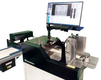
Film Inspection MachinesA film inspection device is a device that inspects for defects that occur during the production of sheets and films.
In our daily lives, films and sheets are used for foodstuffs, home appliances, household goods, and many other applications. On the other hand, most of them are made very thin. However, they are strong enough and do not tear easily.

By adding a film inspection machine to the production line, defects can be inspected during production to ensure that the sheet is up to standard.

Uses of Film Inspection Machines

A film inspection machine is mainly used to check and inspect sheets for various defects and deficiencies in the manufacturing process. Film inspection machines are installed at various stages of the sheet manufacturing process.

In the film forming process, they inspect the base resin for contamination and fish eyes. In the laminating process, they inspect for inclusions and wrinkles. In the coating process, they inspect the application of chemicals. In the slitter and inspector processes, they perform final shipping inspections. Finding various defects in the manufacturing process is effective in maintaining product quality, preventing defects in subsequent processes, preventing yield loss, and improving productivity.

In recent years, the system has also been used to inspect optical sheets, multilayer sheets, high-performance sheets, coated paper, flooring materials, glass sheets, metal foil sheets, nonwoven fabrics, etc., for defects that are difficult to see with the naked eye.

Principle of Film Inspection Machine

Although there is no clear definition, the difference between a sheet and a film is often distinguished by their thickness. In this section, all descriptions are for “sheets.”

1. Sheet Production

Sheets are manufactured from resins, such as polyethylene using an extruder. In this process, the sheet is stretched from a T-die into a thin slit, cooled by a cooling roll, and wound up by a winder to be completed as a product.

This is called the T-die method. Another method is the inflation method, in which air is used to inflate the sheet into a bag-like shape after cooling to make two overlapping sheets.

2. Inspection of Sheet Defects

In the process of manufacturing these sheets, various defects such as thickness variation, color irregularity, fisheye, foreign matter such as dust and oil adhesion, wrinkles and stripes, scratches, pinholes, stains, and filling defects occur. Film inspection machines detect these defects.

In camera-based inspection, an area camera is used to view the entire area to be inspected, and a line camera is used to inspect the line to be inspected all at once. A line camera is best suited for continuous inspection in a line where sheets are flowing.

Multiple high-resolution line cameras are installed in the sheet width direction, and the sensitivity threshold of each camera is set according to the variation in the sheet geometry. Another method is to use a single scanning camera and inspect by high-speed scanning.

It is also important to select an inspection device according to what is to be inspected, such as a device that inspects thickness using a laser beam and a reflective laser displacement meter.

Other Information on Film Inspection Machines

1. Purpose of Film Inspection Machines

The purpose of installing film inspection machines is to ensure the detection of defects by mechanizing inspections, to improve product quality by reducing human errors, and to increase productivity.

Examples of Inspections by Film Inspection Machines

High-Speed Inspection of Sheet Defects
The system consists of three-line cameras, transmissive and reflective LED line lighting, etc. Two cameras are used to inspect the front and back surfaces of the sheet, and one camera is used to inspect and detect defects at high speed using transmissive and reflective LED line lighting.

Detection of Uneven Coating Defects
When coating a sheet, slight variations in thickness can cause uneven coating defects. Film inspection machines using a multi-wavelength camera can clearly detect uneven coating due to the difference in color components.

Wrinkle Defect Detection
When manufacturing transparent sheets, wrinkle defects may occur due to sheet warpage. Wrinkle defects are difficult to detect with monochrome images because the difference between a flat surface and a defect is small. Wrinkle defects can be detected clearly by acquiring RGB images using a multi-wavelength camera.

Discrimination of Foreign Matter and Air Bubbles
When laminating sheets, it is necessary to distinguish slight air bubbles from foreign matter. In monochrome inspection, shiny foreign matter and bubbles cannot be discriminated because they are the same light defect.

However, inspection with a multi-wavelength camera can detect differences in shading information, making it possible to discriminate between them.

カテゴリー
category_usa

CNC Measuring System

What Is a CNC Measuring System?

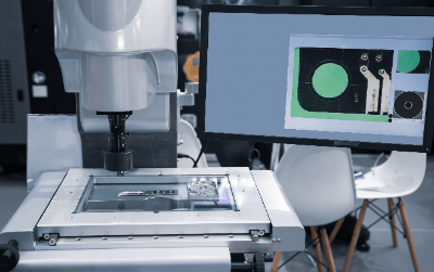
CNC Measuring SystemsA CNC measuring system is a system that uses a CCD camera to magnify the object to be measured to observe its dimensions, shape, and surface properties.
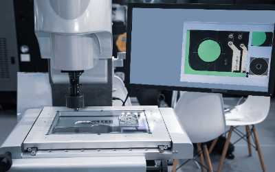
The system can move the object to be measured and the CCD camera to any desired position at high speed and with high accuracy and also perform a non-contact measurement without damaging the object to be measured. In addition, the system enables high-precision focusing by laser and image processing autofocusing, and image processing can find flaws and defects that cannot be observed with the naked eye.

Applications of CNC Measuring Systems

The CNC measuring system is used to perform continuous automatic measurement at high speed and high accuracy. The system is suitable for measurements of very small, identical patterns, such as pattern measurements of substrates and electronic components.

Because humans can become confused and fatigued when they lose track of where they have measured due to the succession of the same pattern, a CNC measuring system that always performs the same operation with high accuracy is indispensable in semiconductor production lines. It is also suitable for items that are not suited for manual measurement, as slight variations in positioning have a large impact on error when measured by humans.

Principle of CNC Measuring Systems

CNC measuring system uses a CCD camera to magnify the object to be measured in order to observe its dimensions, shape, and surface properties, and requires a system to display the image obtained by the CCD camera, to measure the dimensions and surface properties from the image, and to process the image itself.

The installation and use of a CNC measuring system requires a dedicated, temperature-controlled measurement room. This is due to the high precision of the device and the fineness of the object to be measured, which means that temperature fluctuations can have a significant impact on measurement errors.

CNC measuring systems can be operated manually, but most of the work is done through a dedicated controller or PC application software. For fast response and highly accurate positioning, the system uses a mechanism that combines a stepping motor and ball screw with a digital scale to read coordinates and perform feedback control.

Other Information on CNC Measuring Systems

1. CNC Control

CNC control is an abbreviation for “computer numerical control” and refers to the use of computers to control machine tools and other equipment. By automating machine movements such as movement direction and speed through programming, high precision and high-speed operation can be achieved.

CNC control is written using two types of programming languages, G code and M code, in which G code describes the conditions and sequence of machining and movements, such as positioning, while M code serves as a supplement to G code.

2. CCD Camera Configuration

A CCD camera, which is also used in the CNC image recognition system, consists of a microlens, a color filter, and a photodiode, each of which has the following functions.

Microlens
Microlenses are responsible for focusing the light that has passed through the lenses to deliver it to the photodiode efficiently.

Color Filter
Color filters break down light into RGB (red, green, and blue) or CMY (cyan, magenta, and yellow) and deliver the light to the photodiode.

Photodiode
When light is received, photoelectric conversion is performed to generate an electric charge, which is transferred vertically and horizontally. The transferred charge is converted to a voltage at the output of the CCD, and an image is output for each pixel.

Since R, G, and B are assigned to each photodiode, the resolution is reduced to about 1/3 of the original CCD pixel count. The image processing engine complements the image to produce an image with the original pixel count. The RAW format saves the data extracted from the photodiode without any composite processing.

カテゴリー
category_usa

Shape Measurement Sensor

What Is a Shape Measurement Sensor?

Shape Measurement SensorsA shape measurement sensor (profile measurement sensor) is a device that measures the shape of an object.

It is a type of displacement sensor that measures thickness and length, and is often called a shape measurement sensor, especially when it measures curved surfaces, depth, and complex shapes. They are used in manufacturing sites in a wide range of industries, from food to industrial products.

The most common type is a non-contact laser measurement type, which is selected according to the object and the required measurement accuracy.

Applications of Shape Measurement Sensors

Shape measurement sensors are mainly used to measure the external shape of products. They are used for checking the cracks, chips, dents, area, volume, and other finished shapes of products, as well as the state of assembly of parts.

For example, in the food industry, it can automatically detect cracks and chips in cookies and rice crackers, etc. In the case of 3D measurement type products, it can also detect area and volume.

In the case of industrial products, the system can be used to automatically determine whether the processing results of various processed products are good or bad. They are also used to check the shape of welding finishes.

Types of Shape Measurement Sensors

1. Optical Displacement Sensor

There are two types of sensors based on the detection principle of triangulation: those using a PSD as the attending element and those using an image sensor.

2. Linear Proximity Sensor

When an alternating current is applied to a coil, magnetic flux is generated, and when it passes through a metallic object, eddy currents are generated against the object. The direction of this eddy current is such that it generates a magnetic flux that interferes with the generated magnetic flux change.

As a result, the inductance of the coil changes, and by reading the amount of change in inductance, the distance displacement between the coil and the object can be measured.

3. Ultrasonic Displacement Sensor

An ultrasonic wave transmitter is used to send ultrasonic waves to an object, and a receiver is used to receive the reflected waves. The distance is calculated by measuring the time between the transmission and reception of ultrasonic waves.

Principle of Shape Measurement Sensor

1. Optical Cutting Method

In the non-contact laser optical cutting method, a laser is emitted from the sensor on a line, reflected off the object to be measured, and received by the light receiving part (element) to measure the distance to the object. From the measured distance, the actual shape is calculated using triangulation, and shape data can be created. 

2. Measurement Resolution

The entire object is measured continuously by moving the object on a conveyor-like line against a sensor fixed at an arbitrary position. One of the measurement resolutions is determined by the number of times the sensor is captured per unit of time. For example, if a line moves 1 meter per second and captures 1,000 times per second, it is possible to capture the shape in increments of 1 mm.

The results of the measurement are processed by computer and displayed on a display to confirm the results. Some products automatically process measurement results, such as width, height, area, and volume.

Shape measurement sensors are based on the principle of shining a light on an object and having the light reflect off it, so that specialized sensors are required to measure the shape of objects made of glass (such as CCDs and CMOS in electronic components and crystal pieces in quartz crystals), rubber products (such as tires), and objects with colors that do not reflect well.

Other Information on Shape Measurement Sensors

Triangulation

Triangulation is a method of measuring distances between distant points using the principle of triangulation. If the exact distance between two points is known, the distance to a point at a distance from those two points can be calculated as long as the angles between the two points are known.

This is based on the property that a triangle is determined when one side of the triangle and its two end angles are determined.

One of the advantages of the triangulation method in a shape measurement sensor is that it is not easily affected by colors or backgrounds. Unlike the general light-receiving discrimination type, the distance is determined by the laser light reflected from the surface of the workpiece, so the influence of the color and material of the workpiece and background can be suppressed.

For example, even if the workpiece and background are the same color, stable position determination is possible.

カテゴリー
category_usa

Half-Pitch Connector

What Is a Half-Pitch Connector?

A half-pitch connector is a connector with half the pitch length compared to a regular full pitch connector. The pin length of a full pitch connector is 2.54 mm, while that of a half-pitch connector is 1.27 mm. While most full-pitch connectors are manufactured in accordance with the MIL standard, which is a procurement standard for the US military, and the DIN standard, which is a German industrial standard, half-pitch connectors are available in a variety of standards, depending on the manufacturer.

Applications of Half-Pitch Connectors

Half-pitch connectors serve as interfaces for a variety of electronic devices. They are used in many industrial products, such as measuring equipment, industrial robots, semiconductor and LCD manufacturing equipment, bullet trains and other railroad products, ATMs, and power generation equipment. Various manufacturers offer half-pitch connectors with their own standards, so it is important to select a half-pitch connector that is suitable for your application. When used as part of a product, it is recommended to select a product that is available in two versions: a socket side with a half-pitch attached and a plug side with a hole that matches the pitch.

Principle of Half-Pitch Connectors

The following explains the principle of half-pitch connectors. Half-pitch connectors are divided into a socket side with a pitch and a plug side with a hole. The socket side consists of a socket contact with a pitch, a housing, which is the body in which the contact is embedded, and a socket shell, which is a case made of insulating material to protect the housing and socket contact. The plug side consists of a plug contact part with a pitched hole, a housing part, and a plug shell. Each part is secured with a fastener called an eyelet.

Connection methods include board-to-board, device-to-device, and short-circuit connectors, IC sockets, and other electronic components. In the board-to-board connection method, a plug and socket are attached to each board for connection. There are different types of connections, such as horizontal, vertical, and stacking connections.

Half-Pitch Connector Substrates

Half-pitch boards have a component pitch of 1.27 mm, half the 2.54 mm of a normal board, making them quite special, and the lead components that can be mounted on them must also match the half-pitch. Among these, connectors must be used whose pin pitch is compatible with the half-pitch. In the past, the half-pitch was a disadvantage because it was out of the standardized 2.54mm pitch. However, recently, the number of leaded components themselves has been decreasing and most components have become surface-mounted components, so that if the circuit is a low-voltage circuit where insulation can be secured, half-pitch boards and connectors with a smaller area and related half-pitch components can be used. As a result, half-pitch circuit board designs are being reevaluated for automobiles and office equipment.

However, narrower pitch has its downsides, such as migration and tracking, which can lead to dielectric breakdown over time and inevitably reduce reliability. Therefore, in order to use half-pitch connectors, it is necessary to have a clear understanding of the operating environment.

Half-Pitch Connector-Compatible Semiconductors

Half-pitch connector-compatible semiconductors are semiconductor components that can be mounted on a half-pitch board, which is half the normal board pitch. In the recent semiconductor technology trend toward ultimate miniaturization, the smallest half-pitch of wiring with special narrow-pitch patterns, i.e., staggered contacts, best represents the process capability to produce high-density, low-cost integrated circuits on a per-function basis.

In the past, DRAM has continued to lead the field in metal pitch, but it could well be replaced by other products in the future. For example, in MPU logic, its physical gate minimum length has led it to represent the most advanced technology essential for the highest performance. Traditionally, major technological advances have been represented by metal half-pitch, and DRAM is a good example.

カテゴリー
category_usa

Current Sensor

What Is a Current Sensor?

A current sensor is a device that measures the current flowing in a circuit. It is sometimes also referred to as a current sensor.

A current sensors is attached to a circuit or conductor through which current flows and monitors the amount and characteristics of the current passing through it. They are generally rugged in design and can be used for long periods of time.

They can also measure with high reliability when properly installed. Some current sensors are capable of non-contact current measurement and are unique in that they can measure currents at high voltages and in hazardous environments.

However, the appropriate current capacity must be selected according to the current range you wish to measure. This is because there may be cases where the sensor may be damaged if an overload or overcurrent occurs. It is important to check the allowable current range and design appropriately.

Uses of Current Sensors

Current sensors are mainly used in electrical circuits. The following are examples of applications of current sensors:

1. Power Control

Current is monitored and controlled in power suppliers and power converters. In photovoltaic and wind power generation systems, current sensors monitor the amount and characteristics of the generated current to ensure a stable power supply.

They are also used to protect circuits and equipment from overcurrents. In power supply equipment and power circuits, currents exceeding the rated current can be detected by current sensors to activate protective circuits. Overcurrent protection is important to ensure safety from equipment failure due to short circuits, etc.

2. Battery Control

Used in battery management systems to monitor the charging and discharging current of batteries. By measuring the current, it is possible to evaluate the condition of the battery and estimate the remaining capacity. Battery monitoring with current sensors is important in various applications such as electric vehicles and mobile devices.

3. Motor Control

Current sensors are important devices in motor drive control. It measures the motor current and feeds it back to the control algorithm to control the torque and speed of the motor. It is widely used in drives, mainly inverters.

Principle of Current Sensors

The principle of current sensors is to measure current based on Ampere’s law. Ampere’s law describes the relationship between the current passing through a conductor and the magnetic field around the conductor.

According to Ampere’s law, the current passing through a conductor is proportional to the strength of the magnetic field formed around it. Current sensors are capable of detecting the effect of this magnetic field or current and sensing it as a voltage or other signal. Depending on the specific current sensor principle, different methods are used.

Types of Current Sensors

Different types of current sensors exist, depending on the measurement principle. The following are examples of current sensor types.

1. Shunt Resistor Type Current Sensor

This type of current sensor measures the current value by connecting a shunt resistor in series with the circuit in which the current flows. The current flowing through the shunt resistor is calculated by the resistance value and the measured voltage drop according to Ohm’s law. The current can be measured by measuring the voltage at both ends of the shunt resistor whose resistance is known.

The shunt resistor type can measure current with high accuracy. In addition, its simple structure allows it to be manufactured at low cost. They are used on boards and in rectifier circuits for large currents.

2. Hall Effect Current Sensor

A Hall effect current sensor uses a Hall element to detect current. The Hall element is placed near a conductor through which a current flows, and a Hall voltage is generated by the magnetic field. By measuring this Hall voltage, the current is detected.

DC currents can be measured without contact. This type of sensor is used in portable clamp ammeters for DC.

3. Current Transformer Type Current Sensor

This is a current sensor that transforms and measures alternating current. It consists of a conductor that serves as the secondary winding and measures the secondary winding current, which varies according to the primary winding current. This allows the AC current to be calculated.

Because of its low cost and high measurement accuracy, it is widely used in industrial equipment. However, their heavy weight and large area for use are drawbacks.

カテゴリー
category_de

Industrie-Tablet

Was ist ein Industrie-Tablet?

Industrie-Tablets sind Tablet-PCs, die für die Arbeit vor Ort verwendet werden können.

Tablets sind leicht und einfach zu transportieren und haben sich in Privathaushalten weit verbreitet, aber in den letzten Jahren ist die Zahl der Anwendungen in verschiedenen Industriezweigen gestiegen, um die Arbeitseffizienz und Produktivität zu verbessern.

Andererseits unterscheiden sich die für die Arbeit vor Ort erforderlichen Spezifikationen stark von denen für private Tablet-PCs. So sind beispielsweise neben einer hohen Widerstandsfähigkeit wie Wasser- und Staubdichtigkeit sowie Stoßfestigkeit auch eine hohe Leistung für eine komfortable Bedienung und eine robuste Sicherheit zum Schutz vor Informationsverlusten erforderlich.

Anwendungen für Industrie-Tablets

Industrie-Tablets können für Terminals in Fahrzeugen verwendet werden, die Vibrationen und Stößen ausgesetzt sind. Sie werden auch an anderen Orten im Freien eingesetzt, z. B. auf Baustellen, wo sie Regen und Wind ausgesetzt sind. Sie können auch in Innenräumen verwendet werden, wo Wassertropfen und Staub ein Problem darstellen, wie z. B. in Maschinenfabriken und Lebensmittelverarbeitungsbetrieben.

Da verschiedene Standorte unterschiedliche Leistungen und Funktionen erfordern, werden Industrie-Tablets individuell angepasst. Beispiele hierfür sind die vollständige Wasserabdichtung für den Einsatz in Nassbereichen oder die Lackierung in den Unternehmensfarben.

Für Industrie-Tablets gibt es eine breite Palette an Zubehör. Je nach Anwendung können Halterungen, Schultergurte und Handschlaufen verwendet werden.

Funktionsweise von Industrie-Tablets

Industrie-Tablets bestehen wie normale Tablets aus verschiedenen Teilen, wie CPU und Speicher, sowie einem Touchscreen-Display.

Tablets verwenden ein gängiges Betriebssystem (OS) wie Windows, mit unternehmensorientierten Versionen wie Windows 10 IoT Edition.

Eine neue Version eines typischen Betriebssystems wird alle zwei bis drei Jahre veröffentlicht und muss für die weitere Nutzung aktualisiert werden. Die Kompatibilität mit älteren Versionen bedeutet, dass einige Tablets die zuvor verwendete Software oder Geräte nicht mehr nutzen können. Andererseits werden Industrie-Tablets in relativ kurzen Zeiträumen, etwa zwei bis drei Jahren, aktualisiert, und eine Inkompatibilität ist für Geschäftszwecke nicht wünschenswert. Aus diesem Grund sind Industrie-Tablets häufig mit einem Betriebssystem ausgestattet, das keine funktionalen Aktualisierungen erfordert.

Auswahl eines geeigneten Industrie-Tablets

Bei der Auswahl eines Industrie-Tablets muss die Umgebung des Standorts, an dem es eingesetzt werden soll, berücksichtigt werden.

Auf Baustellen, in Fabriken und im Freien, wo es zu Staub- und Wasserverschmutzung kommen kann, ist beispielsweise eine staub- und wasserdichte Ausführung erforderlich. Darüber hinaus sind oft nicht nur Kälte- und Stoßfestigkeit erforderlich, sondern auch die Kommunikationsumgebung ist wichtig.

Beim Einsatz für die Bestandsverwaltung oder das Transportmanagement in Lagern usw. ist zu prüfen, ob das im Unternehmen installierte Bestandsverwaltungssystem oder Kommissioniersystem installiert werden kann, um die betriebliche Effizienz zu verbessern. Bei der Verwendung im Freien, z. B. auf Baustellen, muss der Bildschirm auch bei Regen oder mit Handschuhen problemlos bedient werden können.

1. Staub- und wasserdicht

Staub- und Wasserdichtigkeit sind wichtige Eigenschaften für den Einsatz von Tablets im Freien. Allgemeine Tablet-PCs verfügen zwar auch über eine wasserdichte Funktion, aber die Menge an Staub und Feuchtigkeit, die auf der Baustelle entsteht, ist sehr unterschiedlich, sodass höhere staub- und wasserdichte Funktionen erforderlich sind. Aus diesem Grund werden Industrie-Tablets mit einer dicken Hülle um das Tablet herum versehen und andere Maßnahmen ergriffen.

2. Sicherheit

Auf Industrie-Tablets werden wichtige vertrauliche Informationen wie Produktions-, Logistik- und Entwicklungspläne des Unternehmens gespeichert, sodass auch Maßnahmen zur Informationssicherheit unerlässlich sind. Da Tablets jedoch leicht zu transportieren sind, besteht auch die Gefahr des Verlusts. Um solchen Risiken entgegenzuwirken, sind Maßnahmen wie das Festlegen von Zugangsbeschränkungen, die sorgfältige Aufzeichnung der Entnahme von Informationen, die Installation von Antivirensoftware und die Verschlüsselung von Informationen erforderlich.

3. Funkumgebung

Da die Funksignalumgebung an Außenstandorten schlecht sein kann, verfügen einige Industrie-Tablets über Systeme, die es dem Benutzer ermöglichen, auch in einer Offline-Umgebung Berichte zu erstellen und in Handbüchern nachzuschlagen.

Wenn der Betrieb in einer Offline-Umgebung vorgesehen ist, muss die vorhandene Software die Daten auch lokal und nicht in der Cloud speichern, damit sie offline arbeiten kann.

4. Explosionsschutz

In Chemiewerken und an anderen Arbeitsplätzen, an denen mit organischen Lösungsmitteln gearbeitet wird oder an denen viel Staub entsteht, können elektronische Geräte zu einer Zündquelle werden und schwere Unfälle verursachen. Für den Einsatz an solchen Arbeitsplätzen gibt es auch explosionsgeschützte Tabletten.

Wie andere Industrie-Tablets verfügen auch explosionsgeschützte Tablets über wasser- und staubdichte Funktionen und Sicherheitsmaßnahmen und können vor Ort als Industrie-Tablets eingesetzt werden.

カテゴリー
category_de

Biologisch abbaubare Folie

Was ist eine biologisch abbaubare Folie?

Biologisch abbaubare Folien sind Kunststoffe, die so beschaffen sind, dass sie durch die Einwirkung von Mikroorganismen bis auf die molekulare Ebene von Wasser und Kohlendioxid abgebaut werden können.

Im Allgemeinen handelt es sich bei Kunststoffen um synthetische Polymere, die aus Erdöl gewonnen werden und in der Natur nicht leicht abbaubar sind.

Daher verbleiben herkömmliche Kunststoffe, die im Boden deponiert oder ins Meer gekippt werden, lange Zeit in der Umwelt, ohne in die Natur zurückzukehren, was zu einem ernsten Umweltproblem wird.

Biologisch abbaubare Folien hingegen sind als ressourcenschonende Kunststoffe interessant, da sie von Mikroorganismen abgebaut werden, die in der Natur vorkommen.

Anwendungen von biologisch abbaubaren Folien

Biologisch abbaubare Folien werden hauptsächlich für landwirtschaftliche und bautechnische Materialien, Lebensmittelabfallsammelbeutel und Lebensmittelverpackungen verwendet. Nachstehend sind einige Beispiele aufgeführt:

1. Landwirtschaftliche Mulchfolien

Biologisch abbaubare Folien werden in landwirtschaftlichen Mulchfolien verwendet. Landwirtschaftliche Mulchfolien werden zur Abdeckung von Feldböden verwendet und sind wirksam bei der Regulierung der Bodentemperatur, der Speicherung von Feuchtigkeit und der Bekämpfung von Unkraut und Krankheiten. Durch die Verwendung biologisch abbaubarer Folien in landwirtschaftlichen Mulchfolien wird die Notwendigkeit, gebrauchte Mulchfolien zu sammeln und zu entsorgen, erheblich verringert.

2. Sammelsäcke für Lebensmittelabfälle

Biologisch abbaubare Folien werden auch als Alternative zu Sammelsäcken für Lebensmittelabfälle immer beliebter. Wenn biologisch abbaubare Folien als Sammelbeutel für Lebensmittelabfälle verwendet und direkt in Kompostier- und Methangasvergärungsanlagen verarbeitet werden, können Lebensmittelabfälle ohne Abfall recycelt werden.

3. Markierungsband

Markierungsband wird hauptsächlich zur Kennzeichnung von Bäumen in Bergwäldern verwendet. Es ist allgemein als rotes Band bekannt und wird zur Vermeidung von Gefahren, zur Beschilderung von Strecken, zur Markierung und zu Kontrollzwecken verwendet. Die Verwendung biologisch abbaubarer Folien bedeutet, dass sie nicht entfernt werden müssen und die Bäume nicht beeinträchtigen.

4. Pflanzliche Streufolie

Gemüsefolien werden verwendet, um die Qualität des Gemüses zu schützen. Diese Form der Verpackung ist für den Verkauf und den Transport von Gemüse unerlässlich und verbraucht viel Plastik. Durch die Verwendung von biologisch abbaubaren Folien als Alternative zu den bestehenden Kunststoffen können Sie Ihr Geschäft auf umweltfreundliche und ökologische Weise betreiben.

Eigenschaften von biologisch abbaubaren Folien

Die Rohstoffe für biologisch abbaubare Folien lassen sich grob in biologisch abbaubare Kunststoffe auf Erdölbasis und biologisch abbaubare Kunststoffe auf Pflanzenbasis unterteilen. Polyvinylalkohol (PVA) ist ein typischer Erdölrohstoff, während Polymilchsäure (PLA) ein typischer Pflanzenrohstoff ist.

Obwohl biologisch abbaubare Folien als wenig umweltbelastend gelten, ist es nicht notwendig, alle Kunststoffprodukte vollständig durch biologisch abbaubare Folien zu ersetzen. Die Priorität für den Ersatz richtet sich danach, ob die biologische Abbaubarkeit für Kunststoffprodukte, die eine Umweltbelastung darstellen, notwendig ist.

Die Kriterien für die Entscheidung sind, ob es sich bei dem Produkt um ein langlebiges oder nicht langlebiges Produkt handelt und ob es eine ausreichende Verwertung des Produkts gibt. Besondere Priorität haben nicht dauerhafte Materialien, die sich nicht gut verwerten lassen.

Typische Beispiele sind Angelschnüre und Fischernetze, die etwa 41 % des Abfalls ausmachen. Wenn diese biologisch abbaubar gemacht werden, werden sie, selbst wenn sie in die Umwelt gelangen, von Mikroorganismen im Meer zersetzt, was ein Recycling der Ressourcen ermöglicht.

Arten von biologisch abbaubaren Folien

Im Allgemeinen gibt es zwei Kategorien von Kunststoffen: Thermo- und Duroplaste.

Zu den biologisch abbaubaren Kunststoffen gehören jedoch nur Thermoplaste.

Der Grund dafür ist, dass die Folien schneller abgebaut werden müssen. Zu den chemischen Strukturen, die biologisch abbaubar sein können, gehören aliphatische Polyester und aliphatische Polyamide, die alle zu den Thermoplasten gehören.

Die folgenden Arten von Kunststoffen sind biologisch abbaubar:

1. PLA

PLA, auch bekannt als Polymilchsäure, ist ein Kunststoff pflanzlichen Ursprungs und wird als Biokunststoff eingestuft. Er besteht hauptsächlich aus Stärke von Mais, Zuckerrüben, Kartoffeln usw. und ist biologisch abbaubar.

2. Celluloseacetat (Diacetat)

Celluloseacetat wird aus Holz- und Baumwollfasern gewonnen und durch Veresterung der extrahierten Cellulose mit Essigsäure hergestellt. Es wird als Biomasse-Ressource geschätzt, da es letztlich zu Wasser und Kohlendioxid abgebaut wird.

カテゴリー
category_de

Frostschutz Heizkabel

Was ist ein Frostschutz Heizkabel?

Frostschutz Heizkabel sind Heizgeräte, die dazu dienen, die in den Rohren fließende Flüssigkeit zu erwärmen, um sie vor dem Einfrieren zu schützen.

Frostschutz Heizkabel werden speziell für Wasserleitungen verwendet und sind in kalten Klimazonen, in denen die Temperaturen unter dem Gefrierpunkt liegen, notwendig. Wenn Wasserleitungen einfrieren, wird nicht nur die Wasserversorgung unterbrochen, sondern das Wasservolumen dehnt sich beim Gefrieren aus, was zu Verformungen oder im schlimmsten Fall zum Bersten der Wasserleitungen führen kann. Frostschutz Heizkabel sollen das Einfrieren verhindern, indem sie die Wasserleitungen erwärmen.

Anwendungen von Frostschutz Heizkabeln

Frostschutz Heizkabel werden häufig in kalten Regionen eingesetzt, um das Einfrieren von Wasserleitungen zu verhindern.

Insbesondere sollten Frostschutz Heizkabel verwendet werden, um das Einfrieren von Wasserleitungen zu verhindern, die nicht unterirdisch verlegt sind, sondern an der Oberfläche liegen.

Wenn zu diesem Zeitpunkt nicht der richtige Heizkörper je nach Material der Wasserleitungen ausgewählt wird, können die Wasserleitungen stattdessen beschädigt werden.

Bis vor kurzem wurde für Wasserleitungen hauptsächlich Metall verwendet, z. B. Kupferrohre, doch wurden diese in den letzten Jahren durch Materialien auf Kunststoffbasis wie PVC- und Polyethylenrohre ersetzt. Frostschutz Heizkabel wurden im Zuge dieser Veränderungen bei den für Wasserleitungen verwendeten Materialien ebenfalls verbessert.

Funktionsweise von Frostschutz Heizkabeln

Frostschutz Heizkabel bestehen aus einem Heizelement und einem Stromkabel.

Heizelement und Stromkabel

Das Heizelement besteht aus Nickel-Chrom-Draht oder ähnlichem und erzeugt Joule-Wärme, wenn über das Stromkabel elektrischer Strom angelegt wird. Das Stromkabel kann mit einer Einschaltlampe und einer Betriebslampe versehen sein, um zu überprüfen, dass das Heizelement nicht abgeschaltet ist.

Ein bandförmiger Heizelementabschnitt, z. B. ein Flachkabel, wird um eine Wasserleitung gewickelt, um das Wasser in der Leitung zu erwärmen. Durch das Umwickeln des Heizelements mit einem weiteren wärmespeichernden Band können das Heizelement und das Wasserrohr fest fixiert und das Wasserrohr effizient erwärmt werden.

Kombination mit Frostschutz Heizkabeln

Frostschutz Heizkabel werden oft in Kombination mit Thermostaten verwendet. Der Einsatz eines Thermostats hat zwei Vorteile: Er ermöglicht eine Temperaturregelung und spart Stromkosten, da er nur bei Bedarf heizt.

Es gibt zwei Arten von Thermostaten: Thermostate, die die Außentemperatur messen, und solche, die die Rohrtemperatur messen.

Der Außentemperaturfühler reagiert auf die Außentemperatur und muss nicht an der Rohrleitung angebracht werden. Dies hat den Vorteil, dass er einfach zu installieren ist, kann aber zu einer übermäßigen Erwärmung führen, selbst wenn das Wasser im Inneren ausreichend warm ist.

Rohrtemperaturfühler hingegen messen die Temperatur der Rohrleitungen, sodass keine Gefahr der Überhitzung besteht. Allerdings müssen die Rohrleitungen und der Thermostat fest miteinander verbunden sein, und bei der Installation ist Vorsicht geboten.

Auswahl eines geeigneten Frostschutz Heizkabels

Es gibt viele verschiedene Arten von Frostschutz Heizkabeln, aber die Wahl des Heizkörpers muss sich nach dem Material und der Länge der zu installierenden Rohrleitungen richten.

Ein weiteres Kriterium für die Auswahl einer Frostschutz Heizkabel ist, ob das Stromkabel mit einer Einschaltlampe, einer Betriebslampe, einer Energieverbrauchsanzeige und einem Thermostat ausgestattet ist.

Ein wichtiger Punkt ist das Material der Rohrleitungen und die Art der Beschichtung des Heizelements. Bestehen die Rohrleitungen beispielsweise aus Kunststoff, wie vernetzten Polyethylenrohren, und ist das Heizelement mit Weich-PVC ummantelt, wandert der Weichmacher aus und die Rohrleitungen werden brüchig.

Wählen Sie daher ein Produkt mit einer Gegenmaßnahme für die Ummantelung des Heizelements.

Selbstregulierung von Frostschutz Heizkabeln

In den letzten Jahren haben sich selbstregelnde Heizgeräte ohne Thermostat durchgesetzt. Bei dieser Art von Heizgeräten ist kein Thermostat erforderlich. Das Heizelement wird nicht überhitzt oder brennt durch, sodass ein Ausfall vermieden wird. Das Heizelement ist so konstruiert, dass es sich automatisch in Abhängigkeit von der Umgebungstemperatur erwärmt.

Einige Heizelemente sind auch in Parallelschaltung erhältlich, und es gibt auch Typen, die das Schneiden und andere Bearbeitungen vor Ort ermöglichen. Als Heizelemente werden selbstregelnde Heizwiderstände verwendet.

Außerdem sind sie energiesparend und wirtschaftlich im Betrieb, da sie weniger Zubehör benötigen und leiser sind.

Solange das Gerät an das Stromnetz angeschlossen ist, fallen jedoch Stromkosten an, da der Strom weiter fließt.

カテゴリー
category_de

ASSP

Was ist ein ASSP?

ASSPs (anwendungsspezifische Standardprodukte) sind eine Art von integriertem Halbleiterschaltkreis (IC: Integrated Circuit), bei dem es sich um einen integrierten Schaltkreis handelt, der mit spezifischen Funktionen für eine bestimmte Anwendung entworfen und entwickelt wurde.

Anwendungsspezifische integrierte Schaltungen (ASICs) werden ebenfalls als ICs für bestimmte Anwendungen klassifiziert, während ASICs jedoch kundenspezifische oder halb-kundenspezifische Produkte sind, die nach den Anforderungen des Kunden entworfen und entwickelt werden. Anwendungsspezifische Standardprodukte sind anwendungsspezifische Standardprodukte für spezifische Anwendungen, die in erster Linie von ASSP-Herstellern entworfen und entwickelt werden.

ASSPs können  in Massenproduktion hergestellt werden.

Anwendungen von ASSPs

ASSPs sind Allzweckprodukte, die von Halbleiterherstellern für bestimmte Anwendungen entwickelt und konzipiert und mehreren Kunden angeboten werden.

Da die Hersteller von ASSPs von der Massenproduktion profitieren, da sie ihre Produkte einer großen Anzahl von Kunden anbieten können und je größer das Liefervolumen ist, desto eher werden ASSPs in Produkt- und Komponentenbereichen eingesetzt, an denen eine große Anzahl von Herstellern beteiligt ist.

Konkret werden ASSPs häufig für Funktionen wie Energieverwaltung, Bildverarbeitung, Tonverarbeitung, Datenübertragung und -empfang, Sicherheit und Sensoren in den Bereichen Mobiltelefon, Digitalkamera, Kommunikation, audiovisuelle Geräte, OA-Ausrüstung und Automobil eingesetzt.

Funktionsweise von ASSPs

ASSPs sind anwendungsspezifische Standardprodukte mit integrierten Schaltkreisen für allgemeine Anwendungen.

Anwender von ASSPs setzen diese ein, um bestimmte Funktionen bei der Entwicklung und Herstellung ihrer eigenen Endprodukte oder Zwischenprodukte zu realisieren.

Da es sich bei ASSPs um Standardprodukte handelt, die von ASSP-Herstellern entwickelt wurden, können ihre Funktionen und Leistungen übermäßig oder mangelhaft sein. In der Regel werden ASSPs ohne Mängel ausgewählt, so dass häufig Chips mit unnötigen Funktionen verwendet werden, was den Nachteil hat, dass die Chip-Stückkosten für die Anwender von ASSPs höher sind. Ein weiterer Nachteil ist, dass es beim Einsatz von ASSPs schwierig ist, Leistung und Stromverbrauch für die eigenen Produkte zu optimieren.

Auf der anderen Seite besteht der Vorteil darin, dass keine ASSPs entwickelt werden müssen, da alle Entwicklungskosten vom ASSP-Hersteller getragen werden.

In den letzten Jahren wird in immer mehr Produkten ein System on a Chip (SOC) eingesetzt, das alle oder die meisten der benötigten Funktionen auf einem einzigen Chip vereint.