カテゴリー
category_es

Disyuntores

¿Qué es un Disyuntor?

Los disyuntores son dispositivos eléctricos capaces de interrumpir circuitos con flujo de corriente accidental.

Los disyuntores para baja tensión incluyen disyuntores de cableado para detectar sobrecorrientes y disyuntores de fuga a tierra para detectar corrientes de fuga. Los disyuntores para alta tensión no están equipados con detección de corriente accidental y, por lo tanto, se utilizan junto con relés de protección.

Usos de los Disyuntores

Los disyuntores de cableado también se utilizan como dispositivos de seguridad en los hogares. Originalmente, el término “disyuntor” se refiere a cualquier dispositivo que interrumpe un circuito, pero en el contexto de los cuadros eléctricos domésticos, se les conoce como disyuntores de seguridad.

La instalación de disyuntores tiene como objetivo proteger los circuitos y a las personas de corrientes accidentales, como cortocircuitos y fallas a tierra, que pueden resultar en descargas eléctricas e incendios. Por esta razón, los disyuntores se instalan en productos eléctricos y en los cuadros de distribución eléctrica.

Principio de los Disyuntores

Los disyuntores de cableado suelen ser del tipo electromagnético termodinámico, que se basa en la deformación del bimetal debido a las sobrecorrientes. Cuando fluye una corriente excesiva, se genera calor en el bimetal, lo que causa su deformación y hace que el pestillo se suelte, interrumpiendo el circuito.

Los disyuntores electromagnéticos termodinámicos se pueden restablecer manualmente una vez que el bimetal se ha enfriado y ha recuperado su forma original. Por otro lado, los disyuntores RCD (Residual Current Device) monitorean la corriente en el circuito y se desconectan si detectan una corriente de fuga. Esto se debe a que, en condiciones normales, la corriente de entrada y la corriente de salida deberían ser iguales en un circuito aislado.

La diferencia entre la corriente de entrada y la corriente de salida se conoce como corriente de fuga, y se detecta mediante el campo magnético de un transformador de corriente homopolar incorporado en el RCD. Además, los disyuntores de vacío se utilizan principalmente como interruptores automáticos para altas tensiones. Estos interruptores utilizan el vacío para extinguir el arco eléctrico que se produce al abrir un circuito conductor de corriente.

Cuando se trabaja con altas tensiones, el arco eléctrico no puede ser interrumpido fácilmente y puede dañar la zona de contacto. La capacidad de extinguir el arco eléctrico se conoce como capacidad de apagado, y los disyuntores de alta tensión están diseñados específicamente para lograr este apagado de forma segura y eficiente.

Tipo de Disyuntores

Los disyuntores que protegen contra corrientes de cortocircuito en alta tensión o tensiones especiales de alta tensión tienen, como se mencionó anteriormente, una función de extinción de arco. En función de su mecanismo de extinción de arcos, existen los siguientes tipos

1. Disyuntores de Aire (ACB)

Los disyuntores aireados se utilizan generalmente para disyuntores de bajo voltaje, ya que pueden desconectarse en el aire sin ningún problema. Los disyuntores de baja tensión comunes, como los disyuntores de seguridad, entran en la categoría de disyuntores aireados.

2. Disyuntores de Gas (GCB)

Los disyuntores que apagan el arco rociando un gas inerte sobre los contactos al abrir el circuito eléctrico. El gas hexafluoruro de azufre (SF6) se utiliza como gas inerte, pero el SF6 también es un gas de efecto invernadero, por lo que debe utilizarse con precaución en los Disyuntores.

3. Disyuntores de Aceite (OCB)

Disyuntores que utilizan aceite aislante para apagar los arcos. Hoy en día no suelen utilizarse porque su rigidez dieléctrica es inferior a la del vacío. En el pasado, se utilizaban bifenilos policlorados (PCB) y otras sustancias como aceite aislante, pero su producción ya está prohibida.

4. Disyuntores de Vacío (VCB)

Los disyuntores que extinguen un arco aplicando vacío a los contactos de apertura y cierre. Los disyuntores de vacío son el principal tipo de disyuntores pequeños de alta tensión. Tienen pocos actuadores y son fáciles de mantener.

Más Información sobre Disyuntores

Diferencia entre Disyuntores y Disyuntores

No hay diferencia entre un disyuntor y un interruptor automático. La palabra inglesa para disyuntores es breaker. Breaker es una abreviatura y en inglés un disyuntor se llama circuit breaker. La traducción literal es disyuntores eléctricos.

Cuando los ingenieros eléctricos hablan de disyuntores, la mayoría de las veces se refieren a disyuntores de alta tensión o especiales de alta tensión.

カテゴリー
category_usa

Water Quality Analyzer

What Is a Water Quality Analyzer?

Water Quality AnalyzersAs the name suggests, a Water Quality Analyzer is an instrument designed to automatically measure the condition and properties of water.
In essence, the instrument collects a sample of water from a specific location and places it in the instrument’s sample holder for analysis.

Although we have mentioned that it simply analyzes the properties of water, there are many items that can be measured.

The main items that can be measured are pH, turbidity, conductivity, salinity, and dissolved oxygen.

Some instruments can measure multiple of the items listed above, while others specialize in a single item.

Uses of Water Quality Analyzers

Water Quality Analyzers are used in various places where water is available, especially these days when environmental issues are being called for.

For example, water supply facilities are places where water sent from sewerage facilities is treated in order to send it back to homes and facilities. Water Quality Analyzers are installed to make sure that the treated water meets the required standards.

Water is also essential for the manufacture of products in factories. The water used in factories is dirty and must be treated within the factory to meet standards that allow it to be discharged.

At this point, Water Quality Analyzers are used to measure whether the water meets the effluent standards.

Principle of Water Quality Analyzer

The measuring principle of the Water Quality Analyzer depends on the item to be measured.

The pH is measured by the degree of potential difference between a standard solution and the water to be measured.

The main measuring principle for turbidity is to drop light into the water. The stronger the turbidity, the more light is reflected and scattered, and the less light is transmitted. The measurement is based on how much of this light is transmitted.

Conductivity is measured by measuring the electrical resistance of a standard potassium chloride solution, and the reciprocal of the resistance is the conductivity. The electric conductivity is obtained from the difference in electrical resistance to the potassium chloride solution.

The diaphragm electrode method is the most popular method for measuring dissolved oxygen.

A diaphragm is placed between the working electrode and the oxygenated water, allowing oxygen to permeate through the diaphragm. When oxygen permeates through the diaphragm, a reduction reaction occurs at the working electrode. This reaction causes an electric current to flow, which is measured to determine the oxygen concentration.

The main principle of measurement is described above. This type of measurement method is built into the main body of the Water Quality Analyzer, which measures the sample placed in the sample holder, sends the signal to the detector of the device, and displays each measured value.

カテゴリー
category_usa

Component Analyzer

What Is a Component Analyzer?

A component analyzer is a device that can measure the type and amount of elements present in materials and parts.

Various analysis methods are available depending on the target material or part and the type of element to be detected. By selecting the appropriate method, a highly accurate and sensitive analysis can be performed. Some instruments can be applied not only to solids but also to liquids and gases.

Major analysis targets include medical and pharmaceutical products, metallic materials, organic and polymer materials, food, electronic materials, and various environmentally regulated substances.

Applications of Component Analyzers

Component analyzers are used not only to determine elemental content in the development of new materials and new pharmaceuticals but also to check for the contamination of impurities and hazardous substances.

They are also used to determine what elements are attached to parts when quality or manufacturing problems occur, to inspect foreign substances in products, and to analyze odors.

Component analyzers are also used in environmental analysis for nitrogen oxides (Nox) and carbon dioxide, which are indicators of air pollution, as well as for compliance with RoHS regulations, which have recently become more stringent.

Principle of Component Analyzers

Analysis using component analyzers requires knowledge and experience in each specialized field. Although it is possible to purchase analyzers and perform the analysis, there are various methods for analyzing the same substance, and the parameters to be set for the analysis are very complex. Therefore, it is common for this type of analysis to be outsourced to specialized companies.

Methods for analyzing components include the use of liquid chromatography for purity and impurity analysis of solids that dissolve in liquids or general-purpose solvents. Additionally, FT-IR is used for the chemical structure analysis of solid substances. For solids, there are many methods, such as spark emission spectrometer (ICP), X-ray fluorescence spectrometer, absorption spectrophotometer, FTIR, and mass spectrometer, depending on the element to be measured.

Some industries are required to comply with the RoHS Directive, an environmental regulation for export to Europe. Therefore, it is more efficient to request analysis from a vendor that can handle RoHS compliance.

カテゴリー
category_usa

Box Making Machine

What Is a Box Making Machine?

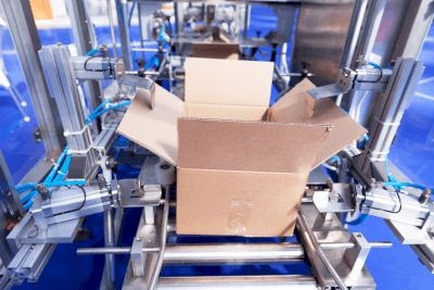
Box Making MachinesA box-making machine is a machine that assembles folded corrugated boxes into a three-dimensional structure and applies tape or hot melt to the bottom of the box, thereby reducing the need for manual labor.
On the other hand, the machine that applies tape to the top surface of a box after its contents have been filled is called a box sealing machine. Some products combine the functions of both.

By incorporating fully automatic box-making machines, which are currently the mainstream, into the production line, the only work required of line workers in the box-making process is the supply of corrugated board sheets, thus achieving significant labor savings.

Applications of Box Making Machines

Box-making machines are used to assemble corrugated boxes in factories and warehouses in a wide range of industries, including manufacturing, agriculture, forestry, fisheries, and mail-order sales.

The most standard type is for assembling and taping A-type corrugated boxes (so-called “tangerine boxes”). However, there are also products that use hot-melt adhesives for gluing, as well as those for assembling one-touch boxes and trays.

Semi-automatic box-making machines perform only the folding of corrugated boxes and tape application by hand, while fully automatic box-making machines perform both box folding and tape application automatically.

Principle of Box Making Machines

In the most common type of box-making machine, which performs the assembly and bottoming of corrugated boxes, corrugated sheets loaded in the magazine section are taken into the machine one by one, the bottom flap is folded, taped, and then discharged from the machine. Electricity and air pressure are used together for power.

Different equipment is needed to assemble different types of corrugated boards. However, the size can be adjusted by operating handles and other controls for the same type of corrugated board.

Various sensors, alarms, and forecasting devices are installed to prevent such problems from occurring or to deal with them when they do occur.

On the other hand, semi-automatic box-making machines exclude the tape application mechanism found in fully automatic box-making machines, so manual work is required for box-making. However, compared to fully automatic box-making machines, semi-automatic box-making machines are sometimes used for cost-effectiveness, since they are smaller, have a simpler structure, are less expensive to install, and can be operated either by electricity or pneumatic pressure.

カテゴリー
category_usa

Infrared Thermometer

What Is an Infrared Thermometer?

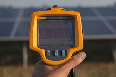
Infrared ThermometersAn infrared thermometer is a device that detects the infrared radiation energy emitted from an object and displays an image of the temperature distribution on the object’s surface. Infrared thermography makes use of the property of infrared radiation that the higher the temperature of an object, the greater the amount of infrared radiation emitted.
Infrared thermometers can:

  1. Measure temperatures from a distance without touching the object
  2. Measure the temperature distribution over a wide area rather than at a single point on the object
  3. Measure temperatures in real time

This is a unique feature of the system.

Applications of Infrared Thermometers

Infrared thermometers are used in a variety of industries for temperature control, monitoring, and inspection due to their ability to provide real-time visualization of an object’s surface temperature.

On construction sites, it can detect invisible peeling of tiles on the exterior of a building by detecting differences in the surface temperature over time. It is also used for preventive maintenance of malfunctions, taking advantage of the fact that electrical equipment tends to reach high temperatures prior to failure.

Because temperatures can be measured hygienically without coming into contact with the object, the system is also used in the food industry to manage the storage conditions of fresh food, detect delivery leaks in prepared foods, and inspect packaging. In addition, because it can quickly visualize a person’s fever status in a non-contact manner, it is widely used as an admission thermometer for facilities that need to take countermeasures against infectious diseases.

Principle of Infrared Thermometers

Infrared thermometers detect the infrared energy emitted from the object being measured and convert this value into a temperature to determine the surface temperature of the object.

In addition to the infrared radiation energy from the object, the infrared thermography detector also receives (a) energy reflected by the object from the surrounding infrared radiation and (b) energy emitted by the infrared thermography itself, so the detected energy contains errors. Since (a) and (b) depend on the ambient temperature, which is measured at the same time as the incident energy, and after making corrections to eliminate the error factors (a) and (b), the infrared energy is converted to temperature.

Infrared energy is proportional to the fourth power of absolute temperature in the case of ideal thermal radiation emitted from a blackbody. In reality, the conversion from infrared energy to temperature is performed using a calibration table, since factors such as the emissivity of the object to be measured, the distance to the object, and the wavelength of the infrared radiation are also included.

カテゴリー
category_usa

Connecting Cable

What Is a Connecting Cable?

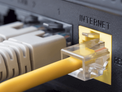
Connecting CablesA connecting cable is a cable used to connect different types of equipment.

A typical example of an old connecting cable is the cable used to connect an NES to a TV. Officially, they are called RCA connecting cables. They transmit signals from the NES to play video and audio on the TV.

Connecting cables are used to connect a component to speakers, a recorder to a TV, and so on, among other applications.

Uses of Connecting Cables

Connecting cables are used in a wide range of applications, from video and audio to industrial applications.

The most common type of connecting cable found in homes is the video cable. In recent years, HDMI cables have been the most commonly used video cables. For audio, coaxial cables have long been used.

LAN cables are also a type of connecting cable. Connecting cables such as USB cables are also widely used for computers.

Principle of Connecting Cable

Connecting cables can be divided into analog and digital signals, although the data to be transmitted and the principle differ depending on the model and signal type.

A typical example of an analog signal is an audio connecting cable that connects earphones, speakers, and amplifiers. The first mechanism of an audio signal connecting cable is that the diaphragm inside the microphone vibrates. The vibration of the diaphragm is transmitted to the coil, which is under the influence of a magnetic field and is converted into an electrical signal as the coil vibrates. The converted electrical signal is processed by a signal amplification device called an amplifier and then transmitted to a speaker or similar device. Speakers have the same structure as a microphone and convert the signal into sound by vibrating a diaphragm. In analog signal processing, most devices continuously take a physical quantity and amplify it after it is converted into an electrical signal.

Typical cables for digital signals are USB cables, LAN, and other connecting cables. Digital signals are structured to transmit signals by repeating two signals, ON or OFF, based on a defined sampling rate. It is resistant to noise, and the amount of data transmitted can be increased by varying the sampling rate.

カテゴリー
category_usa

Washing Basket

What Is a Washing Basket?

Washing BasketsWashing baskets are metal baskets that are used in laboratories and manufacturing departments at companies and universities to wash several or more pieces of equipment at once.
Many of the instruments used in laboratories are made of glass, which can break if dropped, and a large number of instruments are used in a single experiment. Therefore, there is a risk of instrument breakage during the process of carrying individual instruments to the washing area.

By placing the used instruments in the washing basket, they can be brought to the washing area all at once, and after washing, they can be dried in the basket as they are.

Uses of Washing Baskets

Washing baskets are used to clean instruments used in experiments efficiently.

The first is to put all the instruments together in the washing basket before taking them to the washing area.

The second is used at the washing station. When the entire washing basket is soaked in the cleaning solution, the utensils can be removed one by one from the basket and washed.

Third, washed utensils are returned to the washing basket and placed in a large dryer to dry.

This allows for efficient handling of all the utensils at once during the washing process and reduces the risk of damage.

Principle of Washing Baskets

Washing baskets can be rectangular or cylindrical, depending on where and how often they are used.

Stainless steel is the most common material, and stainless steel threads are woven into a wire mesh to form a mesh pattern.

Stainless steel is chosen for its resistance to corrosion, even when exposed to water, and its ability to withstand temperatures ranging from 80 to 100°C when the entire washing basket is placed in a large dryer.

After the wire mesh washing basket is assembled, it is electropolished.

The stainless steel intersections are welded to form a mesh pattern, which is oxidized. This causes rusting and breakage after prolonged use.

In electrolytic polishing, the stainless steel surface is dissolved when the washing basket is placed in a polishing solution and electricity is applied, forming a film on the surface. This film improves rust prevention and maintains quality.

There are washing baskets available that are constructed by perforating round holes in a flat stainless steel plate, as an alternative to using wire mesh. This design provides added strength compared to wire mesh baskets.

カテゴリー
category_usa

Automatic Blood Pressure Meter

What Is an Automatic Blood Pressure Meter?

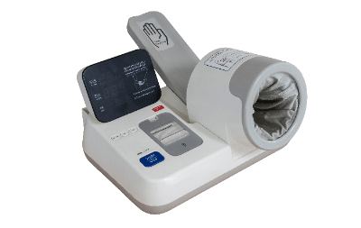
Automatic Blood Pressure MetersThere are various types of blood pressure meters, but an automatic blood pressure meter is designed to be even easier to operate than conventional products and allow anyone to take measurements.
The most common type of sphygmomanometer is one in which a band-like object called a cuff is wrapped around the upper arm of the person being measured. This type cannot measure blood pressure correctly if the cuff is the wrong size or if it is placed in the wrong place.

On the other hand, with the automatic blood pressure meter, you can take a measurement simply by putting your arm through the measuring section. There is no need to wrap the cuff around your arm by yourself, and the optimal pressure is applied simply by pressing a switch for easy measurement. The position and posture of the arm are important for correct blood pressure measurement. Some products are equipped with a function that determines the correct posture based on the angle of the measuring section through the arm and informs the person taking the measurement, making it easier to take correct blood pressure measurements.

Applications of Automatic Blood Pressure Meters

Blood pressure measurement is an important indicator of daily physical condition and is also used to assess the risk of various diseases such as stroke, heart disease, and kidney disease. All hypertensive patients with a blood pressure of 140/190 mmHg or higher, those with an elevated blood pressure of 130-139/80-89 mmHg, and those with a blood pressure of 120/80 mmHg or higher, whose cardiovascular risk increases with rising blood pressure, are considered eligible for blood pressure control. In order to detect abnormalities early, it is important to measure blood pressure regularly and to know one’s own average blood pressure. The automatic blood pressure meter is becoming popular not only in hospitals but also for home use because it is simpler to operate and allows for easy and continuous blood pressure monitoring.

Principle of Automatic Blood Pressure Meter

The Korotkoff method and the oscillometric method are two well-known principles of blood pressure measurement, but the oscillometric method is generally used in the automatic blood pressure meter.

In the oscillometric method, the arterial pulsation caused by the contraction of the heart is measured as the pressure inside the cuff. When the upper arm is placed in the measurement section, the cuff is pressurized and blood flow is stopped. On the other hand, the arterial pulsation is still present even after the blood flow has stopped, and the cuff’s inner pressure oscillates accordingly. Next, as the cuff pressure is gradually decreased, the oscillation of the cuff pressure gradually increases and reaches its peak. As the cuff pressure is further reduced, the cuff pressure oscillation rapidly decreases. The blood pressure value is calculated from the relationship between the cuff inner pressure and the increase/decrease of the cuff inner pressure oscillation in this series of processes.

Generally, the cuff pressure at the time of the rapid increase in oscillation is the maximum blood pressure, and the cuff pressure at the time of the rapid decrease is the minimum blood pressure. In the case of the Korotkoff method, it is necessary to detect the blood vessel sound (Korotkoff sound) when the cuff is depressurized, but the oscillometric method does not require such detection and is said to be a measurement method that is less susceptible to external noise.

カテゴリー
category_usa

Operation Switch

What Is an Operation Switch?

Operation Switches

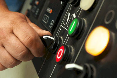
An operation switch is an input device operated mechanically by an external force to switch electrical signals.

These switches are essential for toggling circuits in equipment and device control systems. Their operation involves moving an actuator through direct actions like pressing a button, pulling a lever, or turning a knob.

Consequently, the internal contacts either make or break the circuit, enabling or preventing current flow.

Uses of Operation Switches

Operation switches play a pivotal role in control and power systems, facilitating actions such as power toggling, command issuance, and equipment switching. They enable operators to start, modify, or stop machines during operation.

Operation boxes, or control boxes, house these switches and, increasingly, also feature programmable displays and panel computers as modern input methods.

Principle of Operation Switches

Take the toggle switch as an example: it comprises a body, lever, contacts, and terminals. Activating the lever moves the contacts to switch the circuit ON or OFF.

1. Types of Contacts

Contacts, responsible for circuit continuity, come in three types:

Make Contact (a-contact)
This type remains open (OFF) until operated to close (ON), facilitating load activation.

Break Contact (b-contact)
Normally closed (ON), this contact opens (OFF) upon operation, used for load deactivation.

Break-Make Contact (c-contact)
This contact combines both functions, switching between ON and OFF states upon operation, ideal for circuit toggling.

2. Poles and Throws

The terms “pole” and “throw” denote the switch’s circuit control capabilities, with variations including:

  • Single Pole Single Throw (SPST): Controls 1 circuit with 1 contact
  • Double Pole Single Throw (DPST): Controls 2 circuits with 1 contact
  • Single Pole Double Throw (SPDT): Controls 1 circuit with 2 contacts
  • Double Pole Double Throw (DPDT): Controls 2 circuits with 2 contacts

3. Operation Modes

Switches may operate in alternate or momentary modes, exemplified by push-button switches:

  • Alternate
    Maintains the actuator’s position and contact state post-operation.
  • Momentary
    Resets to the original state upon releasing the switch.

Types of Operation Switches

Variations of operation switches are distinguished by the actuator’s shape and motion, including:

1. Pushbutton Switch

These switches engage contacts via a button press, available in alternate and momentary modes.

Specialized emergency stop switches are designed for visibility and rapid activation.

2. Selector Switch

Selector switches alter contacts through lever rotation, with specifications like notch number and angle, dictating switching capabilities and lever positioning.

3. Rocker Switch

Rocker switches, with their distinctive shape, toggle contacts by pressing a paddle, similar to common light switches.

4. Toggle Switch

These switches operate by moving a lever, with variations supporting different positioning and actuation types.

5. Tactile Switch

Tactile switches are characterized by their short stroke and distinct feedback.

6. Rotary Switch

Rotary switches control circuits through knob rotation, differing from selector switches in internal design.

7. Slide Switch

Operated by sliding a lever, slide switches are another form of tactile actuation.

8. Key Lock Switch

Keylock switches require a key for operation, providing secure access and control.

9. Touchless Switch

These innovative switches detect hand presence without physical contact, employing near-infrared technology for hygienic operation.

10. RFID Switch

Utilizing RFID technology, these switches offer secure, personalized control through tag recognition.

カテゴリー
category_usa

Lead Screw

What Is a Lead Screw?

Lead Screws

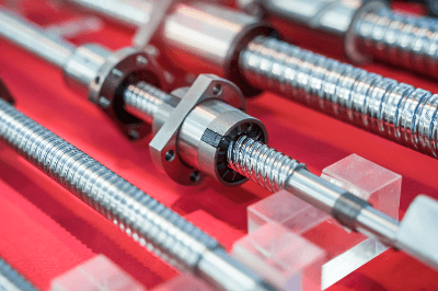
A lead screw is a mechanical element that converts the rotational motion of a screw shaft into linear motion by means of a nut attached to the screw shaft.

Lead screws can convert the rotational motion of a rotary motor into linear motion. There are two types of lead screws: sliding screws and ball screws that use miniature balls.

Ball screws, in particular, use balls to reduce friction and create a structure that allows smooth motion. In either case, they are indispensable mechanical elements for actuators.

Uses of Lead Screws

Lead screws are used in many manufacturing sites that require linear motion, as a wide variety of motors are manufactured and used as the typical power source for rotary motion.

In NC machine tools, they are used to move cutters and workpieces, such as the pedestal movement. Specific examples include machining centers, milling machines, grinding machines, and lathes.

In addition, lead screws are also used in industrial robots, various transport equipment, semiconductor-related equipment, injection molding machines, printing machines, color graphic printers, XY plotters, and automatic drafting machines. In automobiles, feed screws are used in mechanisms for adjusting the irradiation position of headlights.

Principle of Lead Screws

Lead screws convert rotational motion into linear motion because of the screw pitch. The continuous spiral formation of the screw allows the internally threaded parts that mesh with the screw shaft to move continuously in the axial direction where the external thread is formed.

One rotation of the threaded shaft moves the internally threaded parts by one pitch. The direction of travel can also be changed by changing the direction of rotation.

Lead screws can be either plain screws, in which the male and female threads mesh directly, or ball screws, which use balls to reduce friction. However, the principle of converting rotational and linear motion is the same for both types.

Types of Lead Screws

There are two types of lead screws: sliding screws and ball screws. Sliding screws can be further classified into the following types:

1. Triangular Screws

The screw thread has an equilateral triangular shape. The thread shape is almost the same as that of a general fastening screw. While they can be formed by thread rolling and are easy to work with, they are not suitable for parts that transmit power. 

2. Trapezoidal Thread

This is a sliding screw with a trapezoidal thread profile of 29° or 30°. They are easy to process to some extent and can also be used for power transmission. The most common materials used for trapezoidal screws are carbon steel for machine structural purposes and austenitic stainless steel, which is hard and durable for general-purpose products. 

3. Square Screw

The screw threads are square rectangular. Although the positioning accuracy is not high, this screw is advantageous for power transmission. These screws are mainly used in presses, jacks, and other parts that transmit large amounts of force.

Nuts used as mating parts for these Lead Screws are generally made of cast bronze or polyacetal resin (POM).

Other Information on Lead Screws

Accuracy of Ball Screws

Ball screws incorporate rolling balls to reduce friction between the rotating shaft and the nut-side parts, which move linearly with the rotational motion. Multiple parts may be combined, and international and national industrial standards have been established.

There are four accuracy grades defined by ISO standards: C0, C1, C3, C5, and C7. The smaller the number, the higher the accuracy, and the larger the number, the lower the accuracy.

C0 to C5 are used for positioning ball screws, while C7, is used for transport ball screws. The main accuracy grades of ball screws are as follows:

1. Lead Accuracy
Lead accuracy can be understood as positioning accuracy; C0 to C5 are defined by linearity and directional accuracy, and C7 is defined by travel error relative to 300 mm. 

2. Mounting Accuracy
Mounting accuracy of ball screws is defined by several items. For each grade, the allowable values are specified for the circumferential runout of each part of the rotating shaft and the parallelism of the nut’s outer circumference with respect to the standard dimensions.

3. Pressurizing Torque
The preloaded torque is the torque required for positioning with ball screws. If the gap between the screw shaft, ball, and nut is large, accurate positioning is not possible. If the gap is small, torque is required for operation, which is defined by the standard.