ブースタコンプレッサ

ブースタコンプレッサとは

ブースタコンプレッサとは、低圧の圧縮空気や窒素ガスなどを吸い込んで、増圧するコンプレッサのことです。

工場などの圧縮空気ラインの圧力を低い圧力に設定し、ブースタコンプレッサを使用して、高圧が必要なところのみを部分的に増圧することにより、省エネが可能です。

ブースタコンプレッサは、大きく分けると、給油式とオイルフリー式とがあります。

ブースタコンプレッサの使用用途

1. 一般用途

ブースタコンプレッサは、部品を加工する機械工場、自動車や電気機器などの組み立て工場、製鉄所、鉄鋼加工工場、熱処理工場、化学工場などの圧縮空気ラインや窒素ガスを使用するラインなどで、使用されます。

圧縮空気を使用する機器には、低圧から高圧まで各種あります。最も圧力が高い機器に必要な圧力に、空気源の圧力を上げると、空気源の消費電力が大きくなります。この場合、ブースタコンプレッサを使用して、高圧を必要とする機器用に、部分的に増圧が可能です。

2. 特殊用途

プラスチック射出成形用にも使用されます。成形機の手前の圧縮空気管にブースタコンプレッサを設置し、部分的に増圧します。PETボトルなどの生産に使われます。

また、気密試験は、他の機器より高圧空気が必要であり、ブースタコンプレッサを使用して圧力を高くします。

レーザー加工機用ブースタコンプレッサは、レーザー加工機の窒素ガスなどのアシストガスを昇圧するために使われます。3MPa以上の高圧が必要です。

ブースタコンプレッサの原理

ブースタコンプレッサは、低圧の圧縮空気などを吸い込んで、高圧に増圧するものです。工場の圧縮空気ラインの圧力を、0.1~0.5MPaに設定し、高い圧力が必要な機器の手前で、ブースタコンプレッサにより、0.5~3MPaに増圧します。

ブースタコンプレッサには、レシプロタイプが多く使われます。多気筒とし、圧縮比により多段圧縮を行います。4段圧縮で30MPa程度まで増圧が可能です。

ブースタコンプレッサと同様な目的に使われるものに、空気駆動型増圧器があります。これは圧縮空気を使用してシリンダとピストンにより増圧する機器です。空気の使用量が多く、ブースタコンプレッサに比較すると、効率が良くないのが短所です。

ブースタコンプレッサの特徴

ブースタコンプレッサの特徴は主に下記の5つです。

1. 省エネ

ブースタコンプレッサを使用して、スポット的に高圧空気に増圧することにより、大きなエネルギー低減が可能です。圧縮空気ラインの設定圧力を0.1MP下げると、消費電力を約7%低減させることが可能です。

また、高圧空気が必要な所に新たにコンプレッサを設置する場合より、ブースタコンプレッサの方が、電力量を約17%節約できます。

さらに、空気駆動型増圧器と比較すると、ブースタコンプレッサは、消費電力が1/3ぐらいになり、約27%低減します。空気駆動型増圧器は、圧縮空気を駆動源に使いますが、増圧時半分以上エネルギーが無駄になります。

2. 配管末端の圧力低下防止

大きな圧縮空気ラインの末端では、圧力低下が懸念されます。ブースタコンプレッサで、補うことができます。

3. 低騒音・低振動

配管から直接吸入するので、通常の吸入音がなく低騒音です。パッケージタイプのブースタコンプレッサは、必要機器をすべて内蔵し、低騒音・小型で外観が良い特徴があります。

4. 高い体積効率

ブースタコンプレッサの吸入圧力が大気圧ではなく、圧縮空気ラインの圧力、即ち0.1~0.5MPaであるので、体積効率が高く、小さなブースタコンプレッサで大きな空気量が得られます。

5. ロングライフ

連続長時間運転が可能です。中間整備サイクルが10,000時間程度の製品があります。

ブースタコンプレッサの種類

ブースタコンプレッサは、給油式とオイルフリー式の2種類が使われています。

1. 給油式

レシプロタイプのコンプレッサの給油は、はねかけ式やオイルポンプ式で行います。はねかけ式は、クランクケースにオイルをため、クランクシャフトに設置した突起により、オイルをシリンダやクランクシャフト軸受各部、シリンダにかける方式です。

また、オイルポンプ式は、クランクケースのオイルを給油ポンプで吸い上げ、圧力をかけて摺動各部に送油します。オイルはタービン油が多く使われます。

オイルセパレータなどで、含油量を減らしますが、ある程度のオイルが圧縮空気に含まれます。

空気や窒素ガス用のほか、ヘリウムアルゴン用のブースタコンプレッサもあります。

2. オイルフリー式

食品工場などオイルを嫌う所で使われるブースタコンプレッサです。摺動部にはオイルレスベアリングなどを使用します。オイルレスベアリングは、樹脂系、複層系、金属系の種類があります。コンポジット樹脂のピストンなども使われます。

オイルフリー式は多くのメリットがあります。給油装置・給油孔・油溝加工などが不要、ランニングコストの削減、メンテナンスフリー、潤滑油のリサイクル不要と環境保全などです。

ブースタコンプレッサのその他情報

コンプレッサとブースタの違い

コンプレッサは、吸入空気が大気圧 (約0.1MPa) であり、0.1MPa以上の所定の必要な圧力まで上げる機械です。

一方、ブースタは、上流のコンプレッサによる圧縮ガスを吸入し、所定の圧力まで増圧する機械です。

カテゴリー
category_usa

Sand Filter

What Is a Sand Filter?

A sand filter is a device that uses fine sand to filter water. However, since tap water is already very clean, there is no need for such a filtration device.

A sand filter is mainly used to remove contaminants from legally collected groundwater and river water.

They are also used to remove large solids in wastewater treatment plants. As the name suggests, sand filter use sand as the filtering material, so the filtration system can be changed according to the particle size of the sand.

Uses of Sand Filters

Sand filters are mainly used to filter legally collected groundwater and river water, and in wastewater treatment facilities.

Especially in the food industry, beverage manufacturers consume large amounts of water, making industrial water and tap water too expensive and unprofitable.

Therefore, groundwater is pumped up, sand filters are used to remove suspended solids from the groundwater, and hypochlorous acid and other chemicals are added to create water at the drinking water level.

Sand filtration systems are also used to remove suspended solids in wastewater treatment plants by changing the particle size of the sand used as a filter material.

Principle of Sand Filters

Sand filters use sand as the filtering material, so the particle size of the sand is a very important factor in determining its performance.

If the cleanliness of the target water is not determined, it will not be possible to select the appropriate sand as a filter material. Therefore, when extremely clean water is required, sand with a grain size of 0.3 mm or smaller, or even finer, with a grain size of 0.02 mm, is used.

Also, since such fineness increases the pressure drop and reduces the flow of water, there are products that apply pressure to the water to improve the filtration speed.

As the filtration system removes suspended solids, dirt gradually accumulates. Of course, sand filters are no exception. However, it would be inefficient to replace the filter media every time it becomes clogged with debris. For this reason, many sand filtration units use back washing, in which water flows in the opposite direction of the water flow during filtration to clean the filter media inside the unit.

Since the sand filters cannot be used during back washing, it is common practice to install two tanks containing the filter media and use them alternately.

Maintenance of Sand Filters

Sand filters are devices that use stones or sand of various sizes as filtering filter media to remove suspended solids from the water being used. Suspended solids do not disappear, so they accumulate in the device, but the device can be used continuously for a long period by performing a backwash process to clean the device at regular intervals or when there is an interruption in the flow of water.

It would be good if all suspended solids could be removed by back washing. A small amount of suspended solids will remain and adhere to the filter media. If the adhesion to the filter media grows and the media bind to each other, creating a waterway in the filtration layer, the back washing effect will be lost. When the filtration performance is no longer sufficient, such as when the backwash interval becomes short due to obstruction of the flow of liquid, it is time for maintenance. In many cases, it is not possible to check the inside condition of the sand filtration system through an inspection window, so the decision is based on the operating conditions.

Maintenance of the sand filters consists of the following steps: removing the filter media from the manhole release of the filter tower, cleaning the inside, inspecting and repairing missing parts, inserting new filter media starting with the largest diameter stone, placing medium diameter pebbles on top, then small diameter sand on top, replacing the packing at the inspection port, closing the manhole, and then filling the manhole with water for a trial run. Since this process requires a certain amount of time, it is necessary to have two systems, unless there is a period during which the inflow of water can be stopped, such as when the plant is shut down.

Advantages and Disadvantages of Sand Filters

The advantage of sand filters is that they have low running costs and are not prone to breakdowns. The filtering material is hard quartz sand, which causes little loss due to friction between the sand during normal operation and even during back washing. The system is designed to minimize power costs by utilizing the siphon principle, and there is no chemical injection. Since there are few moving parts, breakdowns are also extremely rare.

In contrast, the disadvantages are that since no power is used, filtration takes time due to the filtration speed caused by gravity, and the space required for filtration equipment is large in proportion to the volume of treated water. When productivity per unit is important, other filtration methods may replace it, and since it uses the power of nature, the advantages and disadvantages are two sides of the same coin.
カテゴリー
category_usa

Stone Surface Plate

What Is a Stone Surface Plate?

A stone surface plate is a platform used as a reference plane for precise dimensional measurement and inspection of materials and parts in processing. These plates are typically rectangular and come in various sizes to suit different objects.

They must possess high flatness accuracy and rigidity, to maintain precision even under heavy loads. Both accuracy and size standards are defined by JIS, which also allows for customization like holes and ribs for part fixation.

While JIS specifies both cast iron and stone as materials, the standards for each are quite similar.

Uses of Stone Surface Plate

Stone surface plates ensure a flat surface for activities like marking, machining, or measuring. They provide a reference plane, enabling precise machining and measurement. Their primary attributes include wear resistance and resistance to environmental factors.

Principle of Stone Surface Plate

As a benchmark for flatness (graded according to JIS B 7513), these plates must be rigid to avoid deformation under heavy loads, affecting measurement accuracy. Handling precautions include installation in a controlled environment, away from direct sunlight and sudden air currents.

Characteristics of Stone Surface Plate

Stone surface plates, compared to cast iron, exhibit less aging, higher abrasion and environmental resistance, and are non-magnetic. They require periodic polishing to maintain flatness. Their low aging and high wear resistance extend the time between regrindings, reducing maintenance costs.

Additionally, these plates resist damage from accidental impacts, safeguarding both the plate and equipment. Despite their advantages, the main drawback is the higher cost, attributed to the harder material and longer processing time required for flattening.

Other Information on Stone Surface Plate

1. Grades of Stone Surface Plate

JIS classifies these plates into grades 0, 1, and 2, with grade 0 being the most precise. Flatness tolerance is calculated using constants C1, C2, and the plate’s diagonal length. The cost varies by grade, necessitating selection based on required flatness and size.

2. Care of Stone Surface Plate

Maintenance is crucial for ensuring ongoing accuracy. Regular cleaning prevents surface deterioration and measurement errors. Special cleaners are used, followed by wiping with water and drying with a cloth. Regular flatness checks and protective covering after use are also important.

With proper care, stone surface plates can last semi-permanently without significant changes over time.

カテゴリー
category_usa

Vacuum Gate Valve

What Is a Vacuum Gate Valve?

A vacuum gate valve is a valve element that separates two or more vacuum chambers or the vacuum chamber and the atmospheric environment. They are mainly found in vacuum facilities and semiconductor manufacturing facilities. There are various types of gate valves, such as open/close types, open/close motors, and valve plug structures.

The selection is based on factors such as the pressure difference across the valve plug, the opening/closing speed, the level of dust and dirt generated during opening and closing, heat resistance, chemical resistance, and so on. From small-sized products with a few tens of millimeters in diameter to flat panel display production equipment to large valves several meters wide.

Uses of Vacuum Gate Valves

Vacuum gate valves are used to separate multiple vacuum chambers or to partition a vacuum chamber from the atmosphere. In this case, the vacuum gate valves are used for transferring materials to another vacuum chamber while maintaining a vacuum in one vacuum chamber at all times.

In this case, the vacuum chamber is always kept in a vacuum state while the materials to be processed are transferred to the other vacuum chamber, and the vacuum chamber is partitioned from the atmosphere. The valve is also used to control the flow rate of the gas exhausted from the vacuum chamber by adjusting the valve opening rate.

When used as a flow control valve, a butterfly type valve with a fast opening/closing speed is used.

Principle of Vacuum Gate Valves

There are many variations of the vacuum gate valve, depending on the valve plug and the open/close structure.

The valve plug has an airtight vacuum chamber. The valve plug is equipped with an O-ring and sealing material to maintain the airtightness of the vacuum chamber, and some products have a built-in heater to maintain the same temperature as the vacuum chamber, which is controlled at high temperatures.

  • Elevating Gate Valve
    This is the most common type of gate valve, which opens and closes by moving the valve plug up and down. Smaller types are made airtight by a single action of ascending, while larger types often require two actions of ascending and then pressing down.
    Since both sides of the valve plug create a vacuum, the housing also has an O-ring or other sealed structure. Valve plugs are available in square and round shapes.
  • Door Valve
    The valve that separates the atmosphere side and the vacuum chamber is called a door valve. It is similar to a lift gate valve, but since one side is at atmospheric pressure, it does not have a housing, and the valve disc is pressed against the vacuum chamber to make it airtight.
  • Pendulum Type Gate Valve
    This type of valve has a round valve plug, which opens and closes by moving like a pendulum. It is characterized by its compactness and has the advantage of low dust emission due to the small number of sliding parts.
カテゴリー
category_usa

Hot Wire Anemometer

What Is a Hot Wire Anemometer?

Hot Wire Anemometers

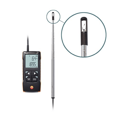
The hot wire anemometer is an instrument that measures wind velocity by using the principle that the hot wire inside the probe is cooled by the wind when the probe is exposed to wind.

Anemometers include vane anemometers and pitot anemometers, but hot wire anemometers are more suitable for indoor measurements where the temperature changes less than with other types of anemometers. The smaller probe size also allows for measurements in tight spaces.

Uses of Hot Wire Anemometer

Hot wire anemometers are primarily used indoors, such as for maintenance management of air conditioning systems and environmental evaluation of clean rooms. The probe, equipped with a sensor, is connected to the main unit by a cable and placed near air vents for measurement.

These devices often measure not only air velocity but also air volume and temperature. However, dust and debris often adhere to the hot wire, affecting the measurement, so periodic maintenance and calibration are necessary.

Principle of Hot Wire Anemometer

There are two types of hot wire anemometers: constant temperature and constant current. The constant temperature type maintains a consistent wire temperature, while the constant current type maintains a consistent current. The constant temperature type is more common due to its superior feedback control.

Hot wire anemometers use the cooling of a heated metal wire to determine wind velocity. The stronger the wind, the more the wire cools, and wind speed is determined by the relationship between wind intensity and heat dissipation. This principle is based on King’s law, stating that heat loss is proportional to the square root of wind speed.

Other Information on Hot Wire Anemometer

1. Temperature Compensation of Hot Wire Anemometer

As hot wire anemometers measure wind velocity based on temperature changes, temperature compensation is necessary to account for wind temperature variations. This is achieved by incorporating a temperature-responsive element and adjusting the heating temperature of the anemometer element in response to wind temperature changes.

2. Advantages of Hot Wire Anemometer

Hot wire anemometers are known for their fast response time due to the small size of the probe and its low heat capacity. Omni-directional probes are available for measuring wind speed without concern for the probe’s direction. However, accurate calibration is crucial for reliable measurements.

Other anemometer types include Pitot tube anemometers, which measure wind speed from the pressure difference, and vane wheel wind velocity sensors, which calculate velocity based on the number of rotations of a vane wheel. The choice of anemometer depends on the specific application requirements.

カテゴリー
category_usa

Titrator

What Is a Titrator?

Titrators

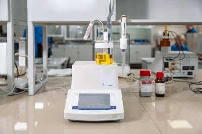
A titrator is a device that can automatically perform various types of titrations. Titration is an analytical method to quantify a target substance in a sample. By slowly adding a standard solution of known concentration to a sample of unknown concentration and measuring the volume required to complete the reaction, the concentration of the sample can be determined.

There are several types of titration, such as neutralization titration, redox titration, and precipitation titration. In ordinary circumstances, titration is performed manually using a burette or other special equipment. However, with a titrator, titration can be performed automatically, including dropping of the solution, determination of the endpoint, and calculation of the concentration.

Uses of Titrators

Titrators can automatically and accurately perform a series of titration operations that are usually performed manually.

Titration is used in the fields of product quality control, analysis, and testing to determine the concentration of a target substance. Since specific components can be accurately quantified, they are used in the purity analysis of compounds, water hardness measurement, and acidity analysis of food products.

Titrators are increasingly being used in research facilities and companies because they cut down on labor hours and enable accurate measurements.

Principles of Titrators

Titration is an analytical operation to quantify a target substance in a sample. By adding a standard solution of known concentration to the target solution and determining the volume required to reach the endpoint, the concentration of the target substance can be determined. Laboratory instruments used in titration operations include conical beakers, burettes, and whole pipettes, which are studied in high school chemistry. An indicator is usually used to determine the endpoint. This is so that the endpoint can be determined by the color change.

Titrators mainly consist of a control panel, burette, stirrer, electrode, and detector. The reagent to be titrated is connected to the burette, and a beaker containing the sample to be measured is placed on the stirrer. Most of the instruments are compatible with the electro-titration method, and the endpoint is determined by measuring the amount of electricity that changes due to the reaction.

カテゴリー
category_usa

Welding Machine

What Is a Welding Machine?

A welding machine is a device used to join resin and nonferrous metals. Two materials are joined by heating them until their melting points are exceeded, and then pressurizing and cooling the joint. It is sometimes called a welder or sealer.

The process of welding, which joins metals together, uses high voltage to melt the metals locally, welding can be operated with relatively small equipment. Welding work must be performed by skilled craftsmen with fire prevention measures in place, but welding machines can be used unattended and are therefore widely used in factories and other product production lines.

Uses of Welding Machines

Depending on the materials to be welded and the conditions of use, there are several types of welding machines, such as electric heaters, ultrasonic, and vibration heating.

Using this heating performance, welding machines are used for joining thin products such as thermoplastic resin films and sheets, and for riveting the joints of various resin components.

In production lines where thin products are rolled and handled, welding machines can be used to join the ends of the previous and next raw rolls when the raw rolls are replaced, allowing the production line to operate continuously without stopping.

Features of Welding Machines

Welding machines differ in structure and weldable area depending on the heating method, and the model should be selected according to the application.

Heat welding machines using an electric heater consist of an electric heater, seal bar, and seal bar pressing mechanism. The seal bar is clamped between the parts to be welded and a high voltage load is applied to the electric heater to heat the seal bar instantaneously. The welding of a large area is possible depending on the cross-sectional area of the seal bar. However, since the pressing surface by the seal bar and the joining surface must be in close proximity, this method is often used for welding thin products such as sheets and films. The machine can also be introduced into mechanized production lines by automating the pressing mechanism of the seal bar.

Ultrasonic welding machines consist of a high-frequency vibration generator such as a Lagrangian transducer and a tip member called a horn, which amplifies and conducts the generated vibration through the horn, causing the object to vibrate at a high frequency. The bonding surfaces of the vibrating objects are heated and welded by potential movement at the molecular level. Unlike a thermal welding machine, only the bonding area is heated, which has the advantage of minimizing the thermal effect on the object. However, because the vibration is amplified and transmitted, the cross-sectional area at the tip of the horn cannot be large, making it unsuitable for welding large areas.

カテゴリー
category_usa

Survey Calculator

What Is a Survey Calculator?

A survey calculator is a type of function calculator that has built-in formulas for survey calculations. With this calculator, one can simply enter the values measured in a survey and get the appropriate answer.

Some also have the ability to import data directly from surveying instruments, add the necessary calculation programs, and even store a large amount of calculation results.

Thus, a survey calculator can be used to improve the efficiency of your surveying operations.

Uses of Survey Calculators

Survey calculators are primarily used to perform complex calculations used in surveying and to store the results of those calculations.

Survey calculators are often used outdoors, including for civil engineering surveys. For this reason, they are built to withstand the elements, with high shock resistance, waterproofing, splashproofing, and dustproofing.

They are also designed to be easy to use so that users can perform calculations at any time during work. For example, some models have side keys, while others allow you to search for the program easily. You want to execute even with one hand, making them suitable for a wide range of on-site operations and contributing to improved work efficiency.

Principle of Survey Calculators

When surveying, the position of an object is determined by measuring its angle and distance. Survey calculators with a built-in program for survey calculations make it easy to perform complex survey calculations by simply entering the measured values.

Some survey calculators also allow you to add the necessary programs later, allowing you to perform a variety of arbitrary calculations. In addition, the calculations can be stored in the calculator’s large memory.

Many survey calculators are designed for outdoor use. When surveying construction sites, many factors can cause a precision calculator to malfunction, such as sudden changes in weather conditions, rain, or dusty conditions. To ensure trouble-free use in such environments, survey calculators are designed to be highly shockproof, waterproof, splashproof, and dustproof. Some are also backlit so that they can work in dimly lit places and at dimly lit times of the day.

カテゴリー
category_usa

Current Meter

What Is a Current Meter?

A current meter is a measuring instrument used to determine the velocity of water flowing in a river or air being discharged from a duct.

Current meter products are developed based on various measurement principles, such as the rotational speed of an impeller or the Doppler effect of ultrasonic waves. While current meters and flowmeters are similar, measuring flow velocity and flow rate, they are generally treated as the same type of measuring instrument.

Uses of Current Meter

Current meters are used in diverse applications, from river and dam surveys to industrial production plants. They are employed to measure river flow velocity, and exhaust gas velocity, control the inflow velocity in plastic injection molding, and manage the inflow of chemical solutions.

When selecting a current meter, considerations include the range of velocities to be measured, durability, maintenance ease, and whether it is a non-contact or contact type. Many models incorporate communication devices for remote monitoring, enhancing work efficiency.

Principles of Current Meter

Current meters are based on two main principles: electric current meters using an impeller and ultrasonic current meters using ultrasonic waves. They typically comprise a measuring section, an information processing device for electrical signals, and a communication device.

1. Electric Type

Electric current meters measure flow velocity by the number of impeller revolutions. A magnet attached to the impeller generates a magnetic field change, which is converted into an electrical signal and transmitted as a pulse to the information processing unit.

The impeller is aligned with the fluid flow direction using weights or similar devices.

2. Ultrasonic Type

Ultrasonic current meters emit ultrasonic waves towards the fluid, measuring the flow velocity based on the phase shift of waves bouncing off the water surface. This non-contact measurement method enables safe, remote monitoring without disturbing the fluid flow.

Types of Current Meter

Beyond electric and ultrasonic types, current meters come in various forms:

1. Differential Pressure Type

The differential pressure type uses an orifice in the fluid path, measuring flow velocity from the pressure difference across the orifice. It is used for gases, liquids, and vapors and is cost-effective, with no moving parts, making it easy to maintain.

2. Electromagnetic Type

Electromagnetic flowmeters apply Faraday’s law of electromagnetic induction. A magnetic field generated at a 90-degree angle to the flow of a conductive fluid induces an electromotive force proportional to the flow velocity. This method is suitable for conductive fluids and is unaffected by liquid properties like temperature, pressure, density, or viscosity.

3. Coriolis Method

The Coriolis current meter uses the Coriolis force, an apparent force in a rotating system, to measure flow. The faster the fluid flows, the greater the Coriolis force and resulting pipe deformation.

4. Thermal Type

The thermal type measures flow velocity based on the heat absorption of a fluid from a heat source. The flow velocity is determined by the temperature difference at two points in the fluid path or the power consumption of a controlled heater that maintains a consistent temperature difference.

5. The Kalman Vortex Method

This method calculates flow velocity by detecting Kalman vortices, which form downstream of a columnar obstacle in the fluid. Some models use piezoelectric elements to detect vortex vibrations, while others employ ultrasonic detection.

カテゴリー
category_usa

Hydraulic Press Machine

What Is a Hydraulic Press Machine?

A hydraulic press machine is a device that uses hydraulic oil and a hydraulic pump to operate a mechanism to shape a material to be processed into a specified shape using a press die.

Press dies are installed on the upper and lower beds of the machine, and when the upper bed is lowered by hydraulic pressure with the material placed on the lower die, the material is clamped between the upper and lower dies to form the desired shape.

Uses of Hydraulic Press Machines

Hydraulic press machines are available in various sizes depending on the applied pressure. 1,000-ton class hydraulic press machines are often used in the automotive industry to process the exterior panels and chassis frames of passenger cars and truck buses. Presses are also used for die castings, forgings, power generation turbines made of CFRP, and other large products that require molding processing power and time.

For deep-drawing shapes such as sinks and stainless steel containers, mechanical presses using a link drive may cause drawing wrinkles and cracks, resulting in quality defects. On the other hand, hydraulic press machines can improve the quality of deep-drawing shapes because the processing speed can be adjusted.

Principle of Hydraulic Press Machines

Hydraulic pressure is a system that uses fluid to transfer energy and is based on Pascal’s principle. Hydraulic press machines use an electric motor to operate a hydraulic pump, which generates hydraulic pressure. That pressurized hydraulic fluid is then sent to the hydraulic cylinder, which moves the upper side of the bed up and down within a range set by the machine.

To achieve relatively high torque, engines, and electric equipment must be combined with an appropriate transmission. In contrast, hydraulic equipment does not require a transmission because the machine is controlled by changing the amount of hydraulic fluid supplied to the cylinder.

Other Information on Hydraulic Press Machines

1. Features of Hydraulic Press Machines

Comparison of Press Force
The cylinder is moved up and down by the hydraulic oil pressure discharged from the hydraulic pump and the flow control valve. Since a large output can be obtained with a small amount of power, the maximum press force of a mechanical press machine is 80,000 kN, while that of hydraulic press machines is 200,000 kN. Compared to the drive motor used in a mechanical press machine, the drive motor used in hydraulic press machines has about 10 times greater output per mass. Therefore, hydraulic machines have the advantage of being lighter and smaller.

Comparison of Machines
Hydraulic press machines have longer operating strokes than mechanical press machines. They can generate high compressive forces and adjust speed and are easy to handle because the relief valve, which is the mechanism of the hydraulic system, prevents overload. These machines also require more maintenance and processing time is slower.

Comparison During Production
Mechanical presses are used for mass production. Mechanical press machines do not require hydraulic oil or hydraulic pumps, are quiet and unaffected by temperatures, do not require the installation of a hydraulic unit, and have the advantage of high processing speeds. Especially in shearing, bending, drawing, and punching processes, presses are suitable for mass production because processing time is short.

2. Points to Note About Hydraulic Press Machines

Because hydraulic press machines generate extremely high pressure, accidents involving serious injury or death are common. Daily maintenance safety and health education are essential. Insufficient machine management due to hydraulic oil leaks, contamination, etc., can lead to malfunctions, and a machine that has stopped may suddenly start moving.

Operators and supervisors need to provide on-site workers with thorough safety and health education, such as by placing safety bars above and below the bed of the press at the end of each operation.