カテゴリー
category_usa

Pressure Gauge

What Is a Pressure Gauge?

Pressure Gauges

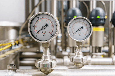
A pressure gauge is a device that measures the pressure of a fluid, such as air or water.

There are different types of pressure, such as constant pressure, fluctuating pressure, and pulsating pressure. And, depending on how the zero point is taken, there can be absolute pressure, gauge pressure, and differential pressure. So it is necessary to select an appropriate pressure gauge depending on the type of pressure to be measured and the output indication method.

Incidentally, a pressure gauge that measures positive gauge pressure is called a pressure gauge, while one that measures negative gauge pressure is called a vacuum gauge.

Uses of Pressure Gauges

Pressure gauges are used in equipment under pressure in factories, plant pipes, and residences and should be selected based on the environment in which they are to be used.

The following are examples of pressure gauge applications:

  • Checking the steam volume of a boiler for steam generation in a factory.
  • Checking the remaining amount of carbon dioxide in a carbonation tank in a restaurant.
  • Measuring the pressure of a compressor.

Principle of Pressure Gauges

Pressure gauges measure pressure by reading the amount of deformation of an elastic body called a pressure-receiving element. There are three types of pressure gauges — Bourdon tube, diaphragm, and bellows — depending on the type of pressure-sensing element, and the principle of each is explained below.

1. Bourdon Tube

Pressure is applied to a metal pipe called a Bourdon tube, causing displacement. The Bourdon tube pressure gauge measures pressure by measuring this displacement, and can do so without the need for external energy such as electricity. Bourdon tube pressure gauges can be further classified into general, compact, sealed, and glycerin-injected types. The Bourdon tube pressure gauge is widely used, but due to its small tube diameter, it cannot be used as is with highly viscous fluids or solids.

2. Diaphragm

Diaphragm pressure gauges measure by converting pressure into an electrical signal through a diaphragm using an element whose resistance value changes according to pressure. Longevity and heat resistance vary depending on whether semiconductors, strain gauges, or thin films are used for the element. Since measurement is made using electrical signals, high-precision pressure measurement is possible. Diaphragm pressure gauges are also suitable for corrosive or highly viscous fluids.

3. Bellows Type

Bellows pressure gauges measure pressure by interpreting the amount of displacement of a bellows-like cylinder with external folds under pressure. Because of its high sensitivity to pressure, the bellows tube type is suitable for measuring relatively low pressures.

How to Use Pressure Gauge

Pressure gauges are used by attaching to the piping through which the fluid to be measured is flowing. For analog gauges, the needle position is read straight from the front of the scale, as with other needle-type analog measuring instruments. In the case of a digital gauge or pressure gauge, the indicated value is read directly.

Since pressure gauges are generally connected directly to piping or other equipment, there are some points to keep in mind when handling them. If a pressure gauge is defective, for example, unintentionally removing it may result in leakage of fluid or injury due to fluid leakage. The pressure in the piping must be reduced during removal. In addition, fluid may remain in the piping or inside the pressure gauge after removal, or a small amount of that fluid may leak out when it is removed. Depending on the fluid being measured, caution may be required during handling.

There are many cases where piping is branched to install a pressure gauge or a branch pipe for measurement. When designing or manufacturing new equipment or machinery that includes piping that handles such fluids, installing a branch pipe for a pressure gauge in advance will minimize the work required when stopping the equipment or machinery and connecting a pressure gauge later.

Selection of Pressure Gauge

There are a variety of pressure gauges on the market intended for different uses. Considerations include:

  • Fluid type – Air, oil, water, nitrogen, oxygen, acetylene, propane, refrigerant, etc.
  • Gauge pressure notation vs. absolute pressure notation – Normally, we live under an atmospheric pressure of about 0.1 MPa. Gauge pressure is the pressure measured under atmospheric pressure as 0 Pa, and absolute pressure is the pressure measured under vacuum as 0 Pa. Gauge pressure is sometimes referred to as PaG and absolute pressure as PaA.
  • Range of pressure to be used – The maximum and minimum pressure that the pressure gauge can withstand, and whether to measure pressure below atmospheric pressure to vacuum.
  • Measurement method of pressure gauges – The type of fluid, pressure range, and accuracy that can be used are determined to some extent by the method, such as Prudhomme Kan, diaphragm, and others.
  • Measurement accuracy required.
  • Pressure gauge size.
  • If there is already a branch pipe for mounting the pressure gauge.
  • The type of connecting joint.
  • The method of mounting the main unit.
カテゴリー
category_usa

Vacuum Vapor Deposition Device

What Is a Vacuum Vapor Deposition Device?

Vacuum Vapor Deposition Devices
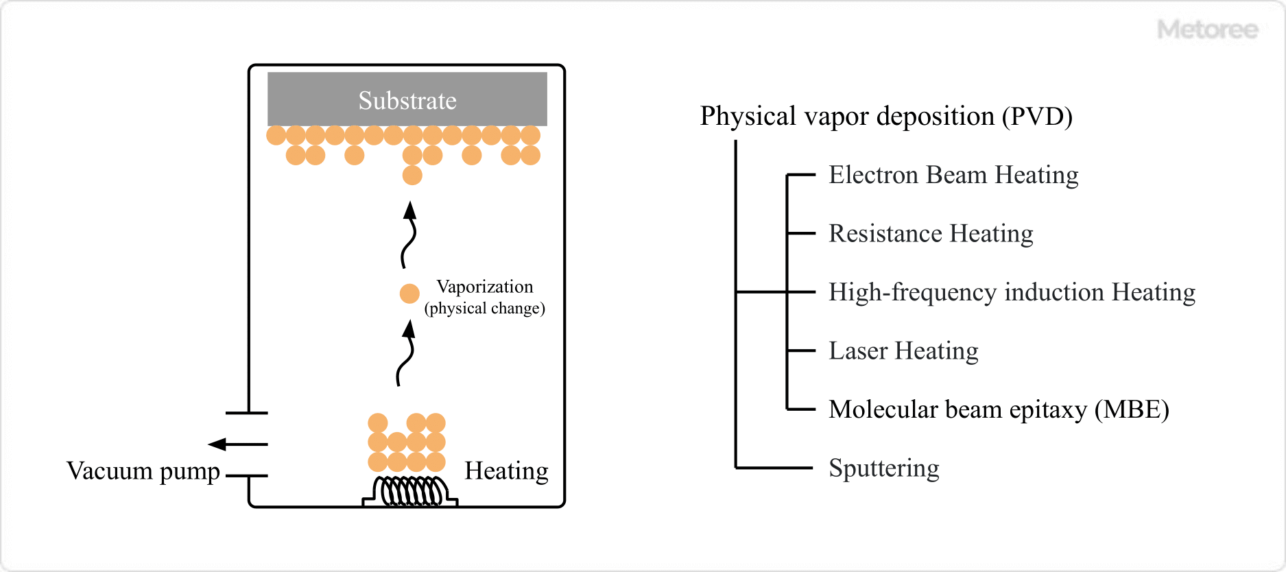
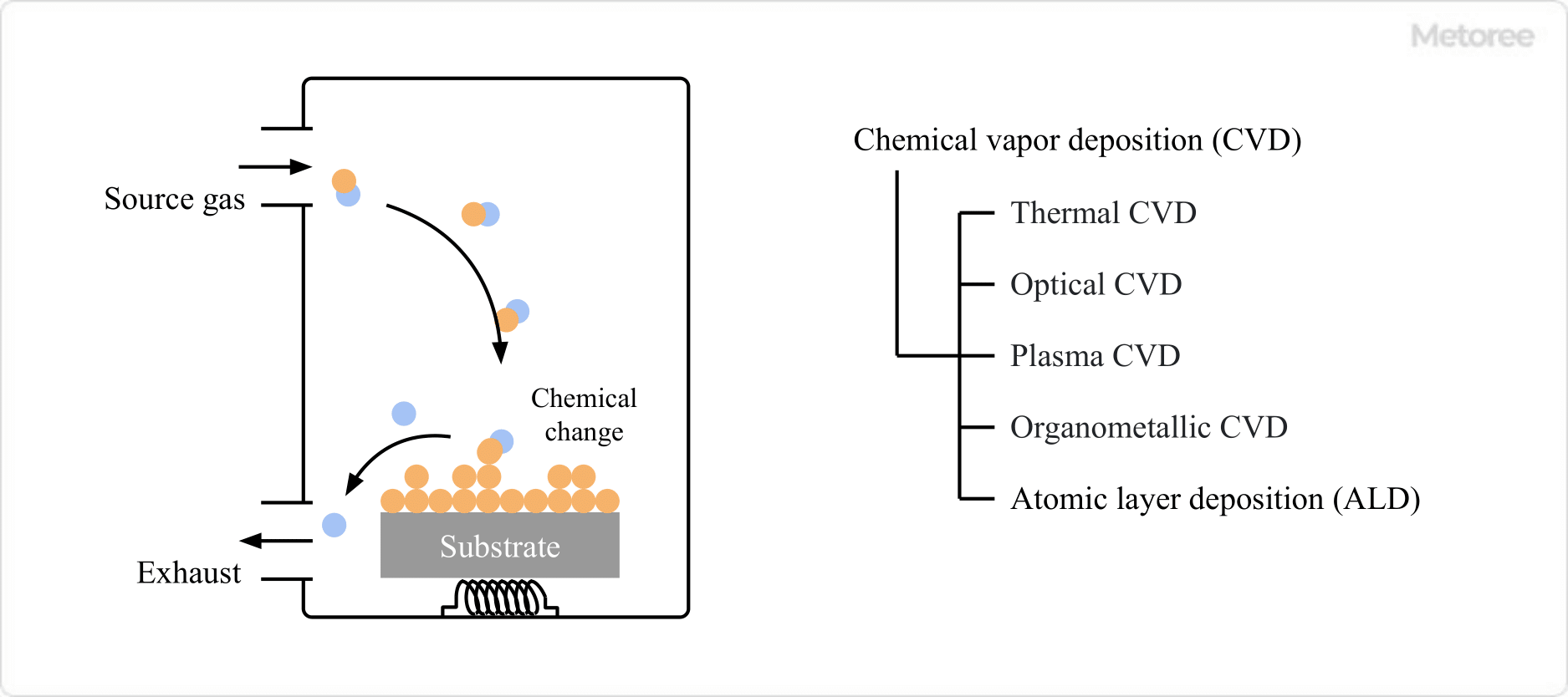
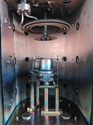
A vacuum vapor deposition device is a device that forms a film on an object by vaporizing a substance under reduced pressure.

A vacuum vapor deposition device can form a smooth coating on an object, and the thickness and composition of the coating can be controlled.

Uses of Vacuum Vapor Deposition Devices

Vacuum vapor deposition devices can form films of various materials, including metallic materials, such as aluminum and organic/inorganic materials.

Vacuum vapor deposition devices are used for the following applications:

  • Optical thin films (antireflection coatings for lenses, special mirrors, etc.)
  • Magnetic tapes (audio and video tapes, etc.)
  • Semiconductors (organic EL, LED, solar cells, etc.)
  • Electronic components (resistors, capacitors, semiconductor integrated circuits, etc.)
  • Food packaging materials (e.g. aluminum evaporated film used for snack bags, etc.)
  • Analytical applications (sample preparations)

Principle of Vacuum Vapor Deposition Devices

Vacuum-Vapor-Deposition-Devices_蒸着装置-1

A rotary pump or turbomolecular pump is used to depressurize the chamber, vaporize the material to be deposited, and deposit it on the object at a distance. The reduced pressure removes impurities from the chamber and improves the diffusion of the vaporized material to produce a smooth film with good adhesion.

Plating is a well-known method of forming a film on the surface of a material. The difference is in plating, raw materials are supplied from the liquid phase, whereas in vapor deposition, raw materials are supplied from the gas phase.

Types of Vacuum Vapor Deposition Devices

Deposition methods used in vacuum vapor deposition devices can be divided into two types according to the method used to vaporize the substance: physical vapor deposition (PVD) and chemical vapor deposition (CVD).

1. Physical Vapor Deposition (PVD)

Vacuum-Vapor-Deposition-Devices_蒸着装置-2

Physical vapor deposition (PVD) is a method of forming films by vaporizing or sublimating evaporation materials through physical means, such as heating. Heating methods include electron beam, resistance heating, high-frequency induction, and laser.

  • Electron Beam Heating
    Vaporization is caused by irradiating the evaporation material stored in a crucible made of refractory materials with an electron beam. Electron beams have high energy and can be applied to materials with high melting points.
  • Resistance Heating
    An electric current is applied to a resistor such as tungsten to generate heat, and the evaporation material is placed on the resistor to heat and vaporize the evaporation material. Since it is relatively difficult to raise the temperature, this method is suitable for materials with low melting points.
  • High-frequency Induction Heating
    The evaporation material is placed in a crucible with a coil wound around it, and a high-frequency current is passed through the coil to generate a strong magnetic field. The current generated by the magnetic field and the heat generated by the electric heat resistance rapidly raise the temperature to vaporize the film material.
  • Laser Heating
    By irradiating the deposition material with a laser, high energy is supplied to vaporize the deposition material.

Plasma and molecular beam methods are also used as physical vapor deposition methods.

  • Molecular Beam Epitaxy (MBE)
    This method uses vacuum deposition in an ultra-high vacuum to align the vaporized molecules in the same direction, allowing for more precise control of film thickness and composition. The growth rate is slow and requires a high vacuum, making it unsuitable for larger equipment and poor for mass production.
  • Sputtering
    When an inert gas, such as argon, is injected into a vacuum and a voltage is applied to the electrode to cause a glow discharge, the plasmaized argon collides with the cathode, repelling atoms and molecules on the cathode. If the object to be deposited is placed on the anode, the repelled atoms are deposited on the surface. Ionization methods include direct current voltage (DC), radio frequency alternating current voltage (RF-AC), magnetrons, and ion beams.

2. Chemical Vapor Deposition (CVD)

Vacuum-Vapor-Deposition-Devices_蒸着装置-3

Chemical vapor deposition (CVD) is a method of forming films by depositing evaporation materials on an object using chemical reactions or other chemical methods. Typical methods include thermal CVD, optical CVD, plasma CVD, organometallic CVD, and atomic layer deposition (ALD).

  • Thermal CVD
    This method uses a resistively heated furnace to create high temperatures, through which raw material gases flow to induce chemical reactions to form thin films. Relatively uniform film thickness can be achieved.
  • Optical CVD
    This method uses ultraviolet lamps or laser beams to cause chemical reactions in a low-temperature process to form thin films. Since no ions are generated, there is little damage to the substrate.
  • Plasma CVD
    Plasma CVD is a method in which the reactivity of raw materials is increased by plasticizing them, causing a reaction to the evaporation target to form a film. High-quality films can be formed because thin films are formed at low temperatures. However, the equipment is expensive and maintenance is difficult.
  • Organometallic CVD
    This method uses an organometallic precursor of the metal to be vapor-deposited as a raw material, which reacts on the target to form a metallic thin film. This method is used for the mass production of LEDs and other devices because it can form films at high speed while precisely controlling film thickness.
  • Atomic Layer Deposition (ALD)
    By depositing and replacing multiple types of raw materials one at a time, the materials react in a controlled manner at a fixed location to form a thin film with a controlled structure and thickness.

In addition to the above, vacuum vapor deposition devices of various methods have been developed and are sold. It is necessary to select the appropriate equipment according to the application.

カテゴリー
category_usa

Contact Sensor

What Are Contact Sensors?

Contact sensors are measuring instruments that measure the distance of the object to be measured by directly contacting a dedicated detector.

Since the distance is measured by bringing the detector into contact with the object to be measured, the advantage of contact sensors is that they are more accurate than non-contact sensors. However, it has the disadvantage of causing a small damage to the object to be measured because it is necessary to place the detector on the object.

Uses of Contact Sensors

Contact sensors are widely used in industrial applications.
The following are some examples of applications of contact sensors:

  • Displacement measurement of thickness of products and test pieces
  • Product inspection and position confirmation of conveying and processing equipment
  • Liquid level control of water storage tanks
  • Providing feedback signals for opening and closing valves and dampers

Contact sensors are typically used for contact displacement sensors. Contact sensors are mainly used to measure the thickness of products and test pieces. In addition to displacement, they may also be used to measure liquid level.

Most non-contact sensors measure distance by projecting a laser or other object and receiving the reflected light. Contact sensors have the advantage of being able to measure large inclined surfaces, which are impossible to measure with reflected light. Taking advantage of this, it is possible to measure the surface profile of a three-dimensional object.

It is also used to measure the displacement of the coarse stage on which the object to be measured is mounted and its movement is controlled, and to measure the runout when the stage is moved in one direction. It can also be used for feedback control from measurement and understanding of errors to adjustment.

Principle of Contact Sensors

Contact sensors, the most common type of contact displacement sensors, generally come with a dedicated probe. The probe has a spindle structure that mechanically extends and retracts up and down. When the probe is not in contact with anything, it is at its maximum extension by spring force.

When the probe comes into contact with the object to be measured, the probe contracts and a constant pressure is applied toward the object by the spring force. The displacement of the probe shaft at that time is detected and converted into length information. Therefore, the range that can be measured is within the range of the probe’s expansion and contraction.

The probe is often wound with a coil, and the shaft part. The shaft part, which serves as the iron core, expands and contracts. However, the expansion and contraction of the iron core depends on the position of the shaft, the impedance in the coil changes and the output changes. Since the impedance is fixed according to the position of the shaft, absolute position can be sensed.

Types of Contact Sensors

Various types of contact sensors are available. The following are examples of contact sensors. 

1. Differential Transformer (LVDT) Type Displacement Sensor

This sensor converts the amount of vertical displacement generated by moving a contactor pressed against the object to be measured into an electrical signal to read the shape of the object to be measured. There is an iron core above the contactor, and the vertical movement of the contactor causes the coil impedance in the vicinity to change, resulting in an electrical signal output.

The structural feature of this sensor is that there is little jump in measurement values. On the other hand, since it uses the magnetic field of the coil, the magnetic field characteristics may not be stable depending on the position of the iron core in the coil.

2. Scale Type Displacement Sensor

Scale sensors digitally measure the amount of displacement of contact sensors. There are two types: magnetic type and optical counting type.

Magnetic Type
The magnetic type measures the displacement by detecting the vertical movement of a scale with alternating S and N poles using a magnetic sensing element. On the other hand, the optical counting type measures the displacement by projecting light onto a scale with many slits and counting the light passing through the slits with a light-receiving element.

Optical Counting Type
The optical counting type is a digital measurement method that is free from noise and can measure with high accuracy. However, rapid movement of the contactor may cause the magnetic sensing element or light-receiving element to react incorrectly, in which case the measured value will jump. 

3. Limit Switches and Microswitches

Limit switches and microswitches are contact sensors that output the position of an object as a contact signal. A dog called an actuator is attached to the tip, which is driven by contact with an object to open and close the internal contacts. Simple and robust in structure, these parts are widely used in industry. 

4. Float-Type Level Sensor

This sensor has a float attached, and the float moves up and down in accordance with the vertical movement of the liquid level to output the level. Because of its simple structure and low cost, it is used in many situations to control the liquid level in storage tanks. However, since the float must be floated in the tank, it is not suitable for tanks that are agitated.

カテゴリー
category_usa

Total Counter

What Is a Total Counter?

Total Counters
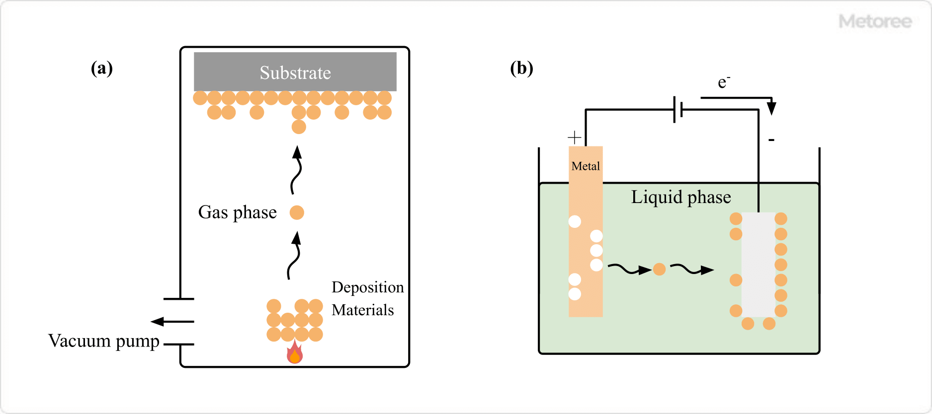
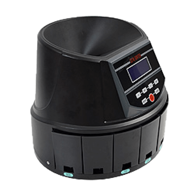
Total counters are devices that count and display the number of operations or objects.

A total counter is a counter that only displays the counted values and is used to check the number of production units visually and the number of operations of factory equipment. The count is maintained until it is reset by pressing the reset button or other means.

It does not have a control output corresponding to the number of counts. Use a preset counter if you want to set the number of counts for output.

Uses of Total Counters

Total counters are widely used in industrial applications. The following are some examples of uses for total counters.

  • Checking the number of times a vacuum breaker operates
  • Checking the number of operations of large dewatering equipment
  • Checking the number of batches of presses and conveyors.

Basically, total counters are used for industrial equipment that operates in batches. Since the service life and maintenance frequency of vacuum circuit breakers, etc., may be determined by the number of times they are operated, a total counter is often attached to the equipment. In addition, huge centrifuges and filter presses generally use a counter to count the number of times they are operated.

Principle of Total Counters

There are two types of counting methods used in total counters.

One is an electronic counter that counts by contact signals or pulses in an electric circuit, and the other is an electromagnetic counter that counts by the magnetic force of an electromagnet built into the counter. The two types of counters are used according to the application and other factors.

1. Electronic Counter

Electronic counters input pulse signals from detection devices, such as rotary encoders and photoelectric switches. Since digital circuit data is stored, it is internally processed as a binary number. The display is generally a 7-segment display.

Many products are available with configurable output sensitivity, such as pulse width and dead time. Compared to electromagnetic counters, detection speeds are also faster. However, in many cases, a power supply is required for operation. Products that can be operated by battery or battery power are also available. 

2. Electromagnetic Counter

This counter is operated by an electromagnet built into the counter, which is triggered by pulses of electrical signals emitted by a detection device. The dial is moved and counted by the force of the electromagnet.

Because counting is performed mechanically, these counters generally do not require an external power supply. They are characterized by the fact that they are not easily affected by noise from detection devices. However, the response of counters is slower than that of electronic counters.

How to Select Total Counters

Total counters are selected according to the input method, power supply method, and other factors.

1. Input Method

The input method is the type of input used for counting. Generally, a no-voltage contact input is used.

Counters that can input transistor contacts are also available. In this case, the input power supply for the transistor must be selected. 

2. Power Supply Method

If the total counters themselves require a power supply, it must be supplied. If it is battery-powered, it does not require an external power supply. However, if it is battery-powered, the battery may run out depending on the time of use.

When supplying power, the main power supply specifications are DC24V, AC100V, AC200V, etc. If you wish to use a commercial power supply as it is, select AC100V or AC200V. When used as an operating counter for equipment that has 24VDC as a control power supply, 24VDC specifications may be selected. 

3. Mounting Method

Total counters are often surface-mounted on the control panel. On the back of the counter, a terminal block or the like is mounted and connected to an internal line of the control panel or the like.

The counter is fixed to the control panel by drilling a hole in the counter, cutting a thread, and fastening with screws. Rubber gaskets are provided on the connection surface to protect the inside of the control panel. Fixing through the packing increases airtightness and prevents water droplets from entering the control panel. Depending on the manufacturer, mounting frames and mounting hardware are sold separately. 

4. Reset Method

Total Counters are equipped with a reset button, which can be pressed to reset the count. Products that can be reset by connecting a no-voltage contact are also available. Select a product with a reset contact if you want to reset with a contact output.

カテゴリー
category_usa

ToF Camera

What Is a ToF Camera?

ToF Cameras
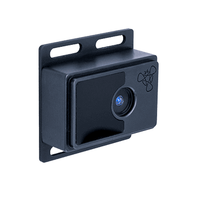
A ToF (time-of-flight) camera is a camera that visualizes the distance to an object by measuring the time of flight of light.

Infrared light is mainly used to measure the distance to an object. The time it takes for the irradiated infrared light to return from the object is measured, and the distance is calculated from this time.

While a normal camera can only obtain two-dimensional information about an object, an image taken with a ToF camera includes depth information, making it possible to obtain three-dimensional information. The method of acquiring information through images, as with a camera, is called “3D-ToF,” while the method of simply knowing the distance is called “1D-ToF.”

Uses of ToF Cameras

ToF cameras have a wide range of applications in industry, medicine, and other fields as follows:

1. Person and Shape Recognition

ToF cameras are used for person and shape recognition. ToF cameras can be used to recognize the movement of a patient in a hospital and be useful when watching over the patient. They can also be installed in stores to track people’s movements and be used in counting the number of people.

Other uses of ToF cameras are in the automated operation of cars. ToF cameras can be used to detect pedestrians so that cars do not rear-end pedestrians.

2. Object Detection and Safety Monitoring

ToF cameras are used in factories and other production sites for object detection and safety monitoring. ToF cameras can be attached to industrial robots and transport equipment to detect intrusion of objects.

In addition, when ToF cameras are installed on presses, robots, and other sources of danger, it is possible to identify whether the approaching object is a transported object or a person. When used to observe crops, measuring their size and shape can be used to determine when to harvest them.

3. Application to Smartphones

ToF distance image sensors are increasingly being used in smartphones, which can accurately capture players’ physical movements and reflect them in games.

Also, when buying or selling something on an e-commerce site, it will be possible to measure and display the dimensions of the object instantly. In addition, ToF cameras are also used for facial recognition when logging in to smartphones.

By identifying the shape of the face with the ToF cameras, the face recognition function is realized. Unlike ordinary cameras, ToF cameras can prevent identity theft because it recognizes the owner’s face as a mere flat surface, even if a photo of the owner’s face is used.

Principle of ToF Cameras

ToF-Cameras_1

ToF cameras consist of a lens, a detector that detects light, and a light source that synchronizes with the detector. The reference light emitted from the on-board light source is reflected by the object and the time it takes to reach the detector (time of flight) is measured.

The speed of light is about 300,000 km/s and is an invariant constant. Therefore, we know that the distance of the target grain is half the product of the two.

Types of ToF Cameras

There are two main types of time-of-flight measurement methods: direct TOF and indirect TOF.

1. Direct ToF Method

In the direct ToF method, a pulse light is irradiated as a reference light and the reflected light pulse is detected. This method measures the time of flight by directly measuring the time from irradiation to detection.

Simultaneously, with the irradiation of the reference light, a measurement pulse current with a known width and period is generated inside the measurement circuit. Time-of-flight can be measured from the difference between the time when the pulse current is generated by the detector and the time when the pulse current is generated by the measurement pulse current and the reflected light.

2. Indirect ToF Method

The indirect ToF method determines the distance from the phase shift with a reference light. The amplitude of the continuous wave emitted from the light source is modulated to generate a sine wave with a known frequency.

This is irradiated onto the object as a reference light, and the phase shift of the reflected light from the object is detected. The phase shift can be converted into a time difference using the frequency of the sine wave. This allows the calculation of the time of flight.

Specifically, the intensity of the reflected light is measured four times for one period of reference light. By discrete Fourier transforming this, the phase shift from the reference light can be obtained.

Other Information on ToF Cameras

Advantages of ToF Cameras

Advantages of the ToF method include its small size, low CPU load, and the ability to be used in dark locations. Each of these advantages is explained below.

1. Can Be Used in Dark Places
The advantage of ToF cameras is that they can be used in the dark because they use infrared light instead of visible light. Three-dimensional information on objects can be obtained even when there is no light source at all in the surroundings.

2. Small Size and Low CPU Load
ToF cameras have a simple device configuration, which allows them to be smaller than structured light systems. Another attractive feature is its low CPU load.

When considering incorporating a ToF sensor into production equipment used at a manufacturing site, a low CPU load reduces the risk of delays and makes it possible to construct a stable production system.

3. Low-cost Products Are Also Available
ToF cameras are not only expensive but also inexpensive, depending on the specifications. Since the price of ToF cameras varies greatly depending on the specifications, it is recommended that you consider the price of ToF cameras in relation to the specifications you need before purchasing.

カテゴリー
category_usa

Contour Measuring Machine

What Are Contour Measuring Machines?

Contour Measuring Machine
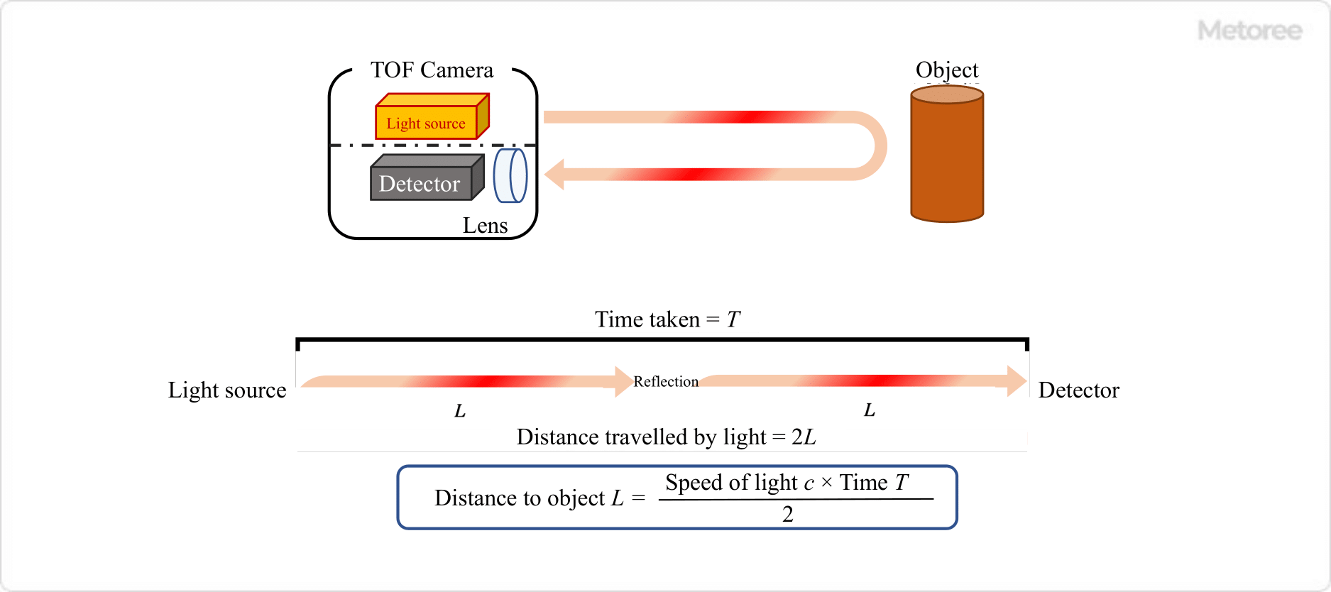
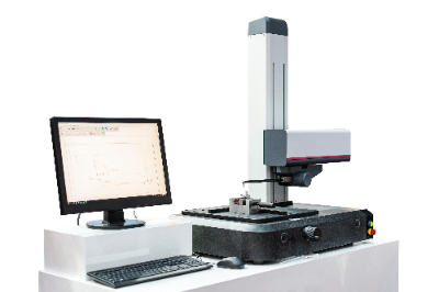
Contour measuring machines are devices that trace the contours of objects and accurately record, analyze, and measure their shapes.

Contour measuring machines that use a stylus to directly trace the surface of the object to be measured and accurately trace its movement are called contact-type contour measuring machines. On the other hand, a non-contact type traces the surface by capturing reflected light from the surface with a laser or other means.

While non-contact contour measuring machines are relatively easy to use, their disadvantage is that the condition of the reflected light varies greatly depending on the material and properties of the object’s surface. For this reason, contact-type measuring machines, which are not affected by conditions, are widely used.

Uses of Contour Measuring Machines

Contour measuring machines are widely used mainly for the development, production, and quality control of metalworking products. In addition, they are sometimes used for automatic measurement on the production line by programming a series of measurement operations.

Since the stylus-type contour measuring machines may scratch the surface, they are often used for spot-checking when the appearance of the product is important. Contour measuring machines can accurately measure shapes and dimensions at a fine pitch, so they can also be used for reverse engineering.

Principle of Contour Measuring Machines

This section describes the principle of widely used contact-type contour measuring machines. Contact contour measuring machines consist of a detector that moves horizontally and a stylus that moves up and down in a large circular arc.

The contour shape can be traced by constantly plotting the coordinates of the stylus tip using a digital scale, with the X coordinate from the horizontal movement and the Y coordinate from the vertical position of the stylus. Note that the arm to which the stylus is attached moves up and down as an arc motion.

In other words, the stylus tip also follows the shape of the object to be measured in a circular arc motion. Therefore, to plot the XY coordinates accurately, the error in the X direction caused by the arc motion must be compensated. Also, if the digital scale used to measure the vertical motion of the stylus can only measure linear motion, a mechanism is required to convert the arc motion into linear motion.

Accurate positioning is critical for detectors, so ball screws and stepping motors are used for this motion. In high-precision machines, electrical components such as the power supply and control board are generally independent as an external box to minimize the effects of thermal expansion.

Other Information on Contour Measuring Machines

1. Tracking Angle of Contour Measuring Machines

Contour measuring machines have a stylus at the end which is mounted vertically on the arm, so it cannot measure at right angles.

The angle at which contour measuring machines can measure is called the tracking angle, which refers to both the up and down directions. The angle of follow-up depends on the shape of the stylus, which has limits in both the ascending and descending directions.

If the stylus has a conical or symmetrical shape, the tracking angles are equal in the up and down directions. However, if the stylus has an asymmetrical shape, the follow-up angles for ascending and descending are different, so care must be taken. The tracking angle also varies depending on the measuring speed and measuring force, and the higher the measuring speed, the more difficult it is to track a steep slope.

2. Daily Inspection of Contour Measuring Machines

Contact-type contour measuring machines are subject to wear because the stylus tip is in contact with the surface to be measured. Even if wear is minimal, it is affected by hysteresis and other changes over time due to repeated use.

Therefore, periodic inspections are necessary, but frequent large-scale maintenance is not realistic in terms of man-hours and cost. Therefore, as a routine inspection, important functions and points related to performance are simply corrected.

Daily inspections of contour measuring machines mainly check and correct the following three points:

  • Accuracy of Measured Values
    We measure a calibrated reference unit, such as a block gauge, and correct any discrepancies between the calibrated value and the actual measured value.
  • Amount of Stylus Tip Wear
    When measuring a valued step, etc., the stylus tip sinks in accordance with the amount of stylus wear, causing a slight discrepancy between the actual shape and the measured shape. Based on this discrepancy, the amount of wear is calculated and corrected.
  • Equivalence of Ascent and Descent Measurements
    Measure symmetrical shapes, such as pin gauges and precision grade steel balls, and correct the distortion between the left and right sides of the measured shape so that they are equivalent.

In most cases, both corrections are automatically calculated by the software from the measured values, so it is important to control the use of the software to remember to perform daily inspections. Furthermore, if you want to obtain and maintain the automotive industry and quality management standards, such as IATF16949 and ISO9001, you must also perform calibration work that ensures traceability on a regular basis.

カテゴリー
category_usa

Remote IO

What Is a Remote I/O?

Remote-IOs-2

A remote I/O is a device used to input, output, and operate measurement remotely. It also inputs and controls devices in factories and other facilities through a network. Because it is used over a network, there is no need for wiring or other complicated wiring settings, and it is effective in reducing noise caused by transporting data over long distances. Remote I/O is widely used in various factories today, where factory automation using IoT, etc. is progressing in order to reduce labor costs and improve production efficiency.

Uses of Remote I/Os

Remote I/Os are used on the factory floor where various factory automations are implemented. They are used to manage in a control room, etc., measurement devices such as temperature, pressure, humidity, current, voltage, etc., collectively that need to be measured and controlled in a factory and that support network communication.

There are many products on the market that support network lines for various measurement devices, and they should be selected appropriately according to the network used by the measurement devices in use.

Configuration of Remote I/Os

A remote I/O consists of a network communication section, a processing unit, and a connection section connected by a single cable. In the connection section, many of the products come with terminals for various connections, allowing you to connect sensors, switches, LEDs, and other control wiring. Some products support more than 60 connections. Remote I/Os can also be connected in parallel. When the number of connections required is insufficient for one remote I/O, or when introducing new electronic components that require new wiring, it is relatively easy to expand by adding additional remote I/Os in parallel. The network communication section connects to a PLC, DCS, or other remote I/O in the control panel via a network.

Principle of Remote I/Os

Remote I/Os, also called distributed I/Os, pass input signals to and from PCs, PLCs, and other master devices in a factory via communication.

1. PLC

PLC, from which remote I/Os pass signals to and from, stands for programmable logic controller, and is a controller used to control equipment and facilities. In manufacturing plants, PLCs control the operation of various devices, such as conveyor belts and sensors.

2. Network

For the networks used by remote I/Os, there are many products on the market that are compatible with the various industrial networks offered by the manufacturers that market PLCs.

Typical industrial networks include EtherNet/IP, EtherCAT, PROFINET, CC-Link, and HLS. Processing equipment handles a variety of communications. Some products use CPUs for high-speed processing, while others provide inexpensive products without CPUs or other components.

Other Remote I/O Information

1. Remote I/O Radio

Remote I/O, or input/output (IO) communication methods for remotely operated devices, include the wired method, in which devices are directly connected to each other with communication lines, and the wireless method, in which a transmitter/receiver is built into the device and communicates wirelessly. Here, Remote I/Os refers to the remote operation of devices using a wireless method.

There are several types of wireless radio communication methods, and Wi-Fi is the most commonly used communication method, especially used in many recent home appliances. However, when Remote I/Os are actually used wirelessly, they are often used in industrial applications such as factories, buildings, and special buildings, etc. In order to cope with the demand for high reliability, there are many cases where each manufacturer uses its own frequency band in the vicinity of 1G. The reliability of the communication method by using the right materials at the right time is the know-how of each company. 

2. Remote I/O Ethernet

The remote I/O ethernet refers to the use of a communication standard called Ethernet for remote input/output of electrical and electronic equipment, known as Remote I/Os. Ethernet is a communication protocol standard from the physical layer to the data link layer in the OSI model, which organizes the functions required for communication between information devices. As a data link layer protocol, its main role is to transfer data reliably within the same network.

Specifically, the role of Ethernet is to transfer data from one Ethernet interface to another Ethernet interface in the same network. And to send data out of an Ethernet interface, each “0” and “1” bit is converted from an electrical signal to a physical signal, and the physical signal received through the Ethernet interface is converted back to an electrical “0” and “1” signal. As a physical protocol, the Ethernet standard also standardizes its physical signal conversion and use of cable media.

3. HLS

HLS is a “one master to multiple slaves” network that can control a batch of digital I/Os at high speed. 63 slave ICs can be connected to one master IC, and a maximum of 2016 I/Os can be controlled.

The HLS master IC has a built-in memory for I/O control registers and communication control registers corresponding to each slave IC.

カテゴリー
category_usa

Mounters

What Is a Mounter?

Mounters are devices that mount electronic components on the surface of printed circuit boards.

Also called a surface mounter or chip mounter, it mounts components of various shapes and sizes at high speed and with high precision. There are two types of mounters: rotary mounters and modular mounters. In recent years, modular mounters, which are compact and have faster mounting speeds, have become the mainstream.

Surface mounting, also called SMT (Surface Mount Technology), is one of the board mounting methods. Electronic components such as IC chips and capacitors are mounted on the surface of a printed circuit board, and the electrodes are fixed in a reflow oven by bonding them with solder paste.

Compared to insertion mounting, where component leads are inserted into holes, this method saves space and has become the mainstream mounting method in recent years. For small-lot production with a small number of boards and components, manual solder mounting by hand is also possible.

Usage of Mounters

There are many boards that are surface-mounted using Mounters, and they can be found almost anywhere that requires boards for electrical circuits. Examples of surface-mounted boards in use are as follows

  • Cellular phones
  • Smart phones
  • Game consoles
  • Home appliances
  • Automotive substrates
  • Airplanes
  • Rockets

They are used in many familiar objects that require circuit boards for electrical circuits. Surface mounting consists of a printing process, a mounting process, and a reflow process. In the printing process, adhesive is applied to the printed circuit board by cream solder printing or dispensing, and Mounters are required to mount electronic components on it. Heat is then applied in a reflow oven to blend the solder and adhesive with the components and adhere the components.

In recent years, the size of electronic components has become less than a few millimeters, making it difficult to mount them by hand. Mounters, which can realize accurate and high-speed mounting of components, are indispensable equipment for board mounting. Mounters that can handle a wide variety of electronic components, including odd-shaped and large components, are available.

Principle of Mounters

Mounters are devices that mount components on printed circuit boards to which solder printing or adhesive has been applied in the previous process. Components set in the feeder are picked up by the suction nozzles in the device and mounted at the designated positions on the board. The structure of the Mounters is as follows

  • Head section
    The nozzle picks up the electronic components.
  • Drive section
    Moves the head section on the XY axis
  • Supply section
    Supplies electronic components to be mounted.
  • Recognition section
    Recognizes the positions of substrates and electronic components with a camera.
  • Transport section
    The printed circuit board is transported.

Mounters are used for mounting electronic components by surface mounting, so after the components are placed using the mounter, the soldering process takes place. Depending on the soldering process, pretreatment before using Mounters is different. In most cases, solder is applied using a cream solder printer or adhesive is applied using a dispenser as pretreatment.

After the board has been pre-processed, electronic components such as chips to be placed are grouped together and placed in the mounter’s feeder. The electronic components are automatically fed from the feeder, and the nozzle of the device sucks the components under negative pressure. The suctioned nozzle moves directly to the top of the board, and the electronic components can be placed and positioned at the set location on the board.

Mounters can be divided into rotary mounters and modular mounters. The mainstream is the modular mounter, which has become smaller and more convenient in recent years. Rotary mounters use a rotary head to pick up and place electronic components. Modular mounters use XY robot axes to move the head to pick up and place the components.

Mounters in recent years have made it possible to mount electronic components in place with high speed and accuracy. The improved performance of the component recognition camera enables highly accurate mounting by measuring and correcting the position of the board and the mounting position of components.

Types of Mounters

There are two types of Mounters: modular type and rotary type.

1. Modular Type

Modular type mounters are currently the most common type of mounters, with a suction header attached to the end of an XY robot, which picks up the component to be mounted and carries it to the mounting position on the board.

While the equipment can be made compact, the disadvantage is that the suction head must be moved in the XY direction each time a component is picked up, resulting in a longer tact time than with the rotary type.

2. Rotary Type

The rotary type has multiple suction heads on a rotating rotary section and can pick up multiple parts in a single pick-up operation. While the rotary type has the advantage of high-speed mounting, it has the disadvantage of large equipment and high maintenance costs.

In addition, it is necessary to set a large number of parts at a time, which is no longer suitable for today’s market, where small-quantity, high-mix production is required. For this reason, most mounter manufacturers have now discontinued production of the rotary type.

How to Select Mounters

The following are things to consider when selecting a mounter.

1. Speed

The speed of mounting a single component varies from about 0.1 second to about 1 second, depending on the mounter model.

2. Mounting Accuracy

For mounting technologies that require miniaturization and high density of components, such as boards for smartphones, an error of about 0.1 mm is required. For circuit boards that do not require high density mounting, a mounting accuracy of about 0.2mm is sufficient.

3.Component Types

When not only chip components wound on tape but also large tray-supplied surface-mounted components are to be mixed on a circuit board, a large mounter capable of setting a special parts feeder is required.

Other Information on Mounters

Mounter Feeder

Mounter feeders are automatic parts feeders that feed electronic components into the equipment. Electronic components are delivered in reel or tray packaging and set in the feeder.

The parts are fed through the feeder into the equipment, and the feeder is an important device for ensuring that the parts are loaded in a constant direction without tilting. The use of a batch feeder exchange cart allows the feeders to be removed and attached from the main unit in a batch, and optimization can be achieved for each cart, thereby reducing the number of setup man-hours.

The feeder size should be selected to suit the packing configuration of the following parts.

  • For reel tape sharing
  • For stick feeding
  • For separate parts
  • Tray feeding

In the reel tape-sharing type, which is the most common delivery form, electronic components are attached to paper tape or plastic embossed tape, which is covered with a thin plastic film tape called cover tape. This mechanism feeds components into the equipment while peeling off the cover tape inside the feeder.

カテゴリー
category_usa

Electromagnetic Contactor

What Is an Electromagnetic Contactor?

An electromagnetic contactor is a device that uses electromagnets to open and close loads, such as motors and heaters.

The electromagnetic contactor is energized when a movable contact is brought into contact with a fixed contact by an electromagnet inside the electromagnetic contactor. The mechanism is the same as that of an electromagnetic relay, but it is used to energize a larger current than an electromagnetic relay.

Uses of Electromagnetic Contactors

Electromagnetic contactors are mainly used as internal components in control panels.

Examples of use are listed below.

  • Lighting control of common lights in condominiums
  • Operation/stop control for pumps that sprinkle water on plastic greenhouses
  • Temperature control of aquarium tanks
  • Operation control of freezers in commercial freezers

As shown above, electromagnetic contactors are mainly used for automatic control.

Principle of Electromagnetic Contactors

Electromagnetic contactors consist of an electromagnetic coil, an iron core, a movable contact, a fixed contact, a return spring, and so on. When open, the return spring lifts the movable contact and separates the fixed contact from the movable contact.

When closed, current flows through the electromagnetic coil. When current flows through the electromagnetic coil, it generates a magnetic field that attracts the movable contacts together with the iron core.

The attracted movable contacts make contact with the fixed contacts and energize the main circuit. When the main circuit is to be interrupted, the current flowing through the coil is interrupted and the return spring lifts the movable contact, thereby interrupting the main circuit.

Other information on Electromagnetic Contactors

1. Difference between Electromagnetic Contactors and Electromagnetic Switches

Electromagnetic contactors are devices that open and close an electric circuit, but it does not provide overcurrent protection.

To provide overcurrent protection, electromagnetic contactors are combined with a thermal relay (thermal relay) to form an electromagnetic switch.

The thermal relay outputs a contact when an overcurrent occurs in order to protect loads, such as motors. Detecting the output of the thermal relay, the circuit is interrupted or an alarm is issued.

The difference between electromagnetic contactors and electromagnetic switches (magnetic switches) is the difference in functionality depending on the presence or absence of a thermal relay.

2. Life span of Electromagnetic Contactors

Electromagnetic contactors control the running and stopping of equipment. Therefore, they are durable enough to withstand the starting current of the equipment many times. If the electrical characteristics are below the rating, the mechanical life is estimated to be 5 million to 10 million times of opening and closing.

3. Precautions when using Electromagnetic Contactors

There are several types of electromagnetic contactors, including standard, reversible, and DC-operated types. Therefore, it is necessary to select electromagnetic contactors with an understanding of their respective characteristics.

  • Standard Type
    The contact operates only while the electromagnetic coil is excited.
  • Reversible Type
    The direction of rotation of rotating equipment can be switched by interchanging the phase order of the contacts.
  • DC-operated Type
    While general electromagnetic contactors operate the electromagnetic coil with alternating current, the DC-operated type operates the electromagnetic coil with a DC power source.

4. Consideration of Back EMF of Electromagnetic Contactors

Back EMF (surge voltage) is generated in the electromagnetic coil of electromagnetic contactors when they are turned on and off. The electromagnetic coil part is generally controlled by a control circuit.

Since devices with low withstand voltage and current are connected to the control circuit, a surge killer may be connected to the electromagnetic coil section to protect the control circuit.

There are three types of surge killers:

  • Varistor Type
    Varistors are used to suppress peak voltage. Peak voltage can be suppressed, but high-frequency components cannot be limited.
  • CR Type
    This is a low-pass filter to limit high-frequency components on the surge voltage.
  • CR + Varistor Type (hybrid type)
    This is a type of surge aspirator that combines a varistor and CR circuit. Both peak voltage and high-frequency components can be limited.

5. Burbling of Electromagnetic Contactors

One of the most common problems is a buzzing noise from electromagnetic contactors. When the coil is AC, the attractive force of the magnetized iron core changes with frequency. In response to this, the iron core is constantly vibrating slightly, and the sound associated with this vibration is called a “whirring sound.”

The whining sound is caused by foreign objects being entangled in the contact surface of the iron core. The fixed iron core and the movable iron core, which are normally in surface contact with each other, make point contact, resulting in a buzzing sound.

If the electromagnetic contactors are disassembled and the foreign matter on the contact surface of the iron core is removed, it can continue to be used. When disassembling the electromagnetic contactors, the power supply should be disconnected and, if possible, the electromagnetic contactors should be removed.

If the electromagnetic contactors cannot be removed from the control panel, use a vacuum cleaner to clean it instead of blowing air on it. This is to prevent foreign objects blown by the air blower from causing a short circuit elsewhere.

カテゴリー
絶対に触らないでください(米国ニュース)

Metoree Surpasses 2,000 Categories in Industrial Products

We are excited to announce that industrial product comparison site, Metoree, has surpassed 2,000 categories of industrial products. This milestone is a testament to our commitment to provide a comprehensive resource for engineers, researchers, and procurement personnel.

Metoree now boasts a vast catalogue collection from over 40,000 manufacturers and dealers, across more than 2,000 categories, including measurement devices, sensors, printing machinery, tools, and much more. This expansion of our category range aims to accommodate a broader spectrum of industrial product needs, making it even easier for professionals to compare and select the most suitable products.

This milestone is a significant step forward in our mission to make Metoree a universal platform for industrial product comparison. Our commitment to continually enhance our platform, coupled with our recent expansions into the German and Spanish markets, reiterates our vision to be a global leader in this sphere.

Thank you for your continued support as we strive to broaden our services and extend our global reach. Stay tuned for more exciting updates from Metoree.