カテゴリー
category_usa

Prism Mirror

What Is a Prism Mirror?

Prism Mirrors

A prism mirror is a device made of glass shaped like a triangular prism, with light-reflecting coatings applied to two sides: one on the slope and the other at a right angle.

The slope-coated type, coated on the slope, can reduce the time required for optical axis adjustment when installed at a 45° angle. The right-angle coated type, with coatings on two right-angled surfaces, can invert and reflect incoming light.

The choice of coating (e.g., broadband dielectric or metal) and base glass material depends on the intended use.

Applications of Prism Mirrors

1. Bevel Coating Type

The bevel-coated type reflects light at a 45° angle, streamlining optical axis adjustment. It’s commonly used in measurement instruments like spectrophotometers.

2. Right-Angle Configuration Surface Coated Type

This type is designed for high-speed image inversion and reflecting light parallel to the optical axis in devices like interferometers. It’s also effective in sunlight harvesting for light capture.

3. BBAR Coating Type

Prism mirrors with broadband anti-reflective (BBAR) coatings are ideal for low-power laser applications. They offer enhanced resistance to mechanical stresses, making them suitable for environments with severe acoustic and inertial loads.

Principle of Prism Mirrors

Right-angle configuration surface-coated types can disperse light into different wavelengths by leveraging the refractive index difference between air and glass. The mirror surface is coated with a material distinct from the glass to achieve this effect.

Coatings can be metallic or broadband dielectric, among others.

1. Metal Coating

Metal coatings, known for high light reflectivity, ensure total reflection of the incident light, altering its angle upon contact with the prism mirror.

2. Broadband Dielectric Coating

Broadband dielectric coatings minimize reflection and enhance light transmission into the glass. They work by coating the glass surface with materials of intermediate refractive indices to suppress unintended reflections.

While a single dielectric layer can reduce reflection, multiple layers with varying refractive indices can further improve transmittance.

Other Information on Prism Mirrors

1. Bonding Prism Mirrors

When bonding prisms, consider the coefficient of linear expansion to prevent cracking due to temperature changes. Flexible adhesives may mitigate this risk but require careful application for stable bonding.

2. Total Reflection

Total reflection occurs when light enters a medium of different refractive index, surpassing the critical angle, leading to light being entirely reflected.

3. Types of Metal Coatings

Various metals, like aluminum for the ultraviolet region and gold for the infrared region, are used for coatings. Base materials like BK7, N-BK7 for precision shapes, and synthetic fused silica for ultraviolet transmission are selected based on application requirements.

Materials with a low coefficient of linear expansion are preferable for temperature resilience.

カテゴリー
category_usa

Platen Roller

What Is a Platen Roller?

A platen roller is a critical component in printers and copy machines that use thermal printing technology. It functions by feeding paper through the printer and ensuring firm contact with the thermal head, facilitating the transfer of ink to paper during the printing process.

Uses of Platen Rollers

Platen rollers are crucial in thermal printing devices, ranging from everyday home printers to advanced multifunction printers in offices. They are key to achieving consistent paper feeding and high-quality prints, especially in devices that print receipts and similar documents. Inkjet printers, which do not use thermal heads, do not require platen rollers.

Principle of Platen Rollers

Platen rollers are integral to both thermal and thermal transfer printing methods, where they press the paper against the thermal head. The choice between these methods depends on factors like print durability and cost, with each having its unique interaction with the platen roller.

1. Thermal Printing

In thermal printing, the platen roller presses thermal paper against the thermal head, which heats up and activates the paper’s heat-sensitive coating to create the print. This method is advantageous for its simplicity and speed, though thermal paper’s sensitivity to heat can be a limitation.

2. Thermal Transfer

The thermal transfer method involves pressing transfer paper and a ribbon against the thermal head with the platen roller. The heat from the head transfers ink from the ribbon to the paper, offering prints that are more resistant to heat and fading.

Structure of Platen Rollers

The typical platen roller consists of a metal core surrounded by a rubber or resin coating, chosen for its ability to grip paper while ensuring even pressure against the thermal head. This design is pivotal for the smooth transportation of paper and the quality of the print output.

Other Information on Platen Rollers

Platen Roller Maintenance

Maintaining the platen roller is vital for continuous high-quality printing and paper handling. Regular cleaning, guided by the printer’s maintenance schedule, involves removing accumulated dust and preventing deterioration, ensuring the roller maintains its grip and paper-feeding efficiency. Following the manufacturer’s maintenance recommendations can significantly extend the life and performance of the printer.

カテゴリー
category_usa

Blow Gun

What Is a Blow Gun?

A blow gun is used when a powerful burst of air is required to remove dust and clean an area. They are commonly found in many factories and laboratories and are frequently utilized.

In most cases, compressed air is used as the gas source, which is easily produced. However, it can also be connected to a nitrogen cylinder for high-pressure nitrogen applications. It’s essential to note that nitrogen and argon do not contain oxygen, posing a risk of asphyxiation when used continuously in enclosed spaces. Therefore, they must be used with proper ventilation for safety.

Uses of Blow Guns

Blowguns are primarily employed for removing dust, sand, wood chips, lint, and other debris from tables, products, and surfaces to clean them effectively.

They also find utility in collecting small parts or sand from barrels, as it is more efficient to blow and collect them using blow guns rather than sweeping with a broom. Additionally, the forceful airflow is highly effective for rapidly cooling hot objects, making them useful for quick cooling of forged products, cast products, and after welding.

Principle of Blow Guns

Blowguns operate by releasing compressed gas, which must be compressed beforehand. Compressed air may be readily available in factories or laboratories, allowing easy connection. In cases where compressed air is not available, it must be prepared separately, typically by connecting to a cylinder or an air compressor. The high-pressure air produced by the compressor is regulated to the desired pressure using a regulator and then connected to the blow gun via a tube.

The release of compressed air is controlled by pulling the trigger attached to the blow gun. The flow rate can be adjusted by manipulating the trigger, allowing for precise control on a case-by-case basis. If the airflow is too vigorous, it can be further adjusted using a regulator installed upstream.

To prevent surface damage when blowing, the tip of the blow gun may be equipped with a rubber tip or a similar device to avoid scratching equipment.

カテゴリー
category_usa

Bridge Breaker

What Is a Bridge Breaker?

A bridge breaker is a device used to eliminate bridging (powder clogging). It is mainly installed in hoppers or tanks where powdered raw materials are used.

When the powder is used, the weight and pressure of the powder itself often cause the powder to harden near the discharge port in the hopper, preventing proper discharge.

Also known as rat hole breakers, there are vibrator, knocker, aerator, blow disk, and break rod types.

Uses of Bridge Breakers

In hoppers where powder is used, there is a possibility of powder clogging called bridging, as well as other abnormalities such as ratholes, in which powder sticks to the sides or top of the hopper.

If bridging or ratholes occur, the rotary feeder at the bottom of the hopper operates, but the powder cannot be fed according to the set weight. The vibrator type is used for this purpose.

The knocker type is used to break up bridges at once by delivering a strong impact to the hopper.

The aerator type is used to prevent bridges and ratholes by supplying air to the inside of the hopper without impact or vibration.

The other type is the blow disk type, which vibrates the inside of the hopper while supplying air, and the break rod type, in which a shaft (claw) is inserted into the hopper and rotated to eliminate bridging.

Principle of Bridge Breakers

The vibrator type uses a ball vibrator or a piston vibrator. In the ball vibrator, a built-in steel ball rotates at a high speed to produce vibration. Piston vibrators are of the cylinder type, and vibrations are produced by the piston motion of the internal cylinder caused by air. Both types are mainly pneumatic.

In the case of the knocker type, the piston type is the main type. When compressed air is supplied, it is directed to a part called the valve chamber and stored in a part called the storage chamber. When exhaust air is released from the three-way valve installed in the air supply piping of the knocker-type bridge breakers, the compressed air stored in the storage chamber moves the part called the knocker’s umbrella valve upward. After the umbrella valve moves, compressed air passes through the piston section, pushing the piston up vigorously.

The blow disk type has a silicon disk that vibrates inside the hopper to eliminate bridging. The disc is pushed up by a jet of air from just below the disc, thereby producing vibration.

The brake rod type can be manually unclogged. A handle is attached to the outside of the hopper, and turning it rotates a shaft inserted into the hopper, which stirs the powder. This type has the disadvantage of being more labor-intensive than the other components that are automatically controlled, and the hopper must be small enough to be installed.

カテゴリー
category_usa

Blank Flange

What Is a Blank Flange?

A blank flange, also known as a blind flange, is a type of pipe flange used to terminate the flow of fluids in piping systems. It serves as a stopper by sealing the end of a pipe and is essential for pressure testing, maintenance, or future expansions of piping networks. Unlike other flanges, a blank flange does not have a center opening for fluid passage but is equipped with boltholes for securing it to a mating flange with a gasket in between to ensure a leak-proof seal.

Uses of Blank Flanges

Blank flanges are versatile components used across various sectors, including oil and gas, chemical processing, and water treatment plants, for temporary or permanent closure of pipeline systems. They facilitate safe maintenance and inspection activities by isolating sections of the network and preventing contamination and leaks.

Principle of Blank Flanges

The effectiveness of a blank flange lies in its ability to provide a secure and tight seal at the end of a pipeline. When installed, a gasket is placed between the blank flange and its mating flange, and the assembly is then fastened with bolts and nuts. This setup prevents any fluid from bypassing the closed section, ensuring the integrity of the system under various operational conditions, including high-pressure and high-temperature environments.

Types of Blank Flanges

Selection criteria for blank flanges include the nominal diameter, pressure rating, material, and gasket seat type, tailored to the specific needs of the piping system. The nominal diameter matches the piping system’s dimensions, ensuring compatibility and a proper fit. The pressure rating corresponds to the system’s maximum operating pressure, with materials chosen based on their resistance to the conveyed fluid’s corrosive or thermal properties.

  • Nominal Diameter: Matches the piping to ensure compatibility.
  • Nominal Pressure: Corresponds to the system’s maximum operating pressure.
  • Material: Selected based on resistance to corrosion and temperature.
  • Gasket Seat: Includes full face (FF), flat face (RF), fitted (MF), and groove (TG), selected based on the type of gasket and sealing requirements.

Other Information on Blank Flanges

Standards governing blank flanges ensure uniformity and safety across applications, with common standards including ASME/ANSI B16.5 and ISO 7005-1. Gasket selection is crucial for achieving a reliable seal, with options like spiral-wound gaskets for high-temperature and high-pressure applications, joint sheet gaskets for general use, and ring joint gaskets for specialized industry standards.

カテゴリー
category_usa

Floating Nut

What Is a Floating Nut?

A floating nut is a nut that allows the tap position to move freely within a certain range and can be tightened even if the centers of the parts to be fixed are off-center.

It can be installed simply by drilling a hole in a thin plate, such as sheet metal, without using a special tool, and the range of movement of the tap is ±2 mm or less from the center value.

Some nuts have a spring structure and can be used for a wide range of plate thicknesses, and since they are removable, they can be removed and reused elsewhere.

Uses of Floating Nuts

Floating nuts are used in the interior of industrial machinery and panel attachments.

Floating nuts are particularly effective for parts where dimensional accuracy is difficult to achieve, or where the tapping position needs to be adjusted due to accumulated tolerances.

Since the tapping position can be adjusted, it is used in place of additional tapping work in areas where accuracy is required.

It is also used to strengthen taps when screwing parts with weak strength, such as thin sheet metal and aluminum.

Since the position of the tap is not stable, this type of nut is not suited for parts that require precision positioning between parts.

Principle of Floating Nuts

The tapping function can be provided simply by making a round hole. This eliminates the need to tap the male thread and reduces the time required to process the part. Also, positional accuracy of the hole machining is not necessary because the position can be adjusted.

However, the cost of floating nuts is higher than simple tapping, with many parts costing over 100 yen, so cost-effectiveness must be considered.

Various types are available depending on the mounting method.

There are not only types called clips, hooks, and racks, which fit laterally but also types called cages, which push into square holes to secure them in place. Floating nuts of the clip type are vulnerable to forces in the direction of clip disengagement, so care must be taken where they are installed.

Self-clinching floating nuts are also available.

Stainless steel or steel material + plating are available, and they are compatible with coarse-grained screws.

カテゴリー
category_usa

Floating Joint

What Is a Floating Joint?

A floating joint is a joint that permits eccentricity and angular misalignment between members. Eccentricity and angular misalignment can be absorbed by sliding the internal spherical structure and the holder covering the sphere.

It is mainly used to connect cylinders, which are linear actuators, to guide rails and other linear moving parts.

Although the basic structure is the same as that of a ball joint, a floating joint cannot be used to transmit rotational or oscillating motion because it is not a joint for rotation or oscillation.

Uses of Floating Joints

Floating joints are mainly used to connect linear actuators, such as cylinders driven by compressed air or electric power, to linear moving parts such as guide rails.

However, unless both actuators are assembled with a high level of precision, a large resistance force may be generated due to eccentricity or angular misalignment, or the cylinder may be damaged.

In contrast, the use of floating joints allows eccentricity and misalignment to be tolerated, eliminating the need for parallelism and centering, and making it possible to construct a linear motion system easily.

Principle of Floating Joints

Floating joints consist of a sphere, a holder to hold the sphere, and screws and nuts to connect the parts. Due to physical constraints, the holder must cover more than half of the sphere’s surface to hold the sphere, so there is a limit to the allowable angular deflection.

Typical floating joints are set at an allowable eccentricity of about 5°, and if the eccentricity is greater than this, the resistance will increase or the joint will break. As described above, the eccentricity and angular misalignment allowances are only to simplify the work of aligning parallelism and centering during assembly, and cannot be used for transmission between members with widely different centering directions, such as ball joints and universal joints.

In addition, since failure occurs due to damage to the sphere or holder when a large impact force is applied, it is necessary to use a cylinder with an air cushion or rubber cushion or install an external shock-absorbing mechanism such as a shock absorber.

カテゴリー
category_usa

Flow Cytometer

What Is a Flow Cytometer?

A flow cytometer is a device used to perform a measurement method called flow cytometry.

In this method, a laser beam is shone on cells in a fluidized liquid sample to detect scattered light and fluorescence emitted from the cells and measure characteristics such as cell size, number, and intracellular and surface antigens.

Compared to fluorescence microscopy, flow cytometers have advantages such as simultaneous quantification of multiple measurement items and high analysis speed. However, flow cytometry is not suitable for observing the morphological characteristics of cells.

Uses of Flow Cytometers

Flow cytometers are widely used for research in the biological and medical fields that handle cells, as well as for clinical testing and treatment. The types of cells that can be measured vary. Peripheral blood leukocytes and other cells are analyzed for disease diagnosis, and cultured animal and plant cells, adult stem cells, tumor-initiating cells, and other rare cells are also analyzed for characterization.

Other cell types that can be measured include microorganisms, marine organisms such as plankton, sperm, yeast, and latex beads.

Principle of Flow Cytometers

Flow cytometers consist of three main components: a flow path system, an optical system, and an electrical system. The flow path system has the function of taking in a sample and pushing it into a flow cell. A laser beam is then applied to the flow cell from the optical system, which consists of a light source, lens, filter, and a detector that generates a photocurrent.

The fluorescence emission from the cells is detected and analyzed by the electrical system. The flow path system consists of tubes, valves, and pumps, and the fluorescently labeled cells suspended in the sample are aligned in a row by the flow path system for analysis.

When the cells pass in a single file through the laser light, called the interrogation point, the light is scattered, and at the same time, fluorescence is emitted by the excitation of the fluorescent dye bound to the cells. This scattered light and fluorescence are detected as a signal by the detector. There are two types of scattered light signals: forward scattered light (FS) and side scattered light (SS).

Different detectors are used to detect FS and SS, with FS reflecting cell size and SS reflecting intracellular structure. The detected signals are converted into data in an electronic system and finally can be interpreted by software.

Other Flow Cytometer Information

1. Analyzer and Cell Sorter

Flow cytometers are divided into two types: cell analyzers and cell sorters. Cell analyzers are devices that analyze cells. Cells in the sample solution, which is wrapped in a sheath fluid, are aligned one by one by a flow cell and flow through the detection section. A laser is then irradiated, and the cells are analyzed by detecting light scattering and fluorescence emission.

Cell analyzers are simple and easy to operate. In addition to cell analysis, cell sorters can also fractionate cells of interest. In addition to analyzing the structure, size, and proportion of cells, the cell sorter can also examine the distribution of cells at high speed and perform preparative sorting.

Cells of interest are given a positive or negative charge to form droplets. Only the droplets of charged target cells are collected in a test tube or microtube by a polarizer, with a voltage applied to change their direction of movement. Cell sorters are more complex and require more skill than cell analyzers.

2. Antibodies for Flow Cytometry

There are two types of antibodies used in flow cytometry for cell detection: polyclonal antibodies and monoclonal antibodies. Polyclonal antibodies are purified from sera collected after immunizing animals with antigens. These antibodies are mixtures of antibodies that recognize and bind to multiple epitopes (antibody binding sites).

To produce monoclonal antibodies, animals are immunized with antigens, and then the antibody-containing B cells are fused with myeloma (cancerous) cells. The resulting hybridoma secretes antibodies that are monoclonal antibodies. This antibody recognizes only one epitope.

Most antibodies for flow cytometry are monoclonal antibodies because they improve the accuracy of the experiment and the specificity of the detection of the target substance (antigen).

カテゴリー
category_usa

Flexible Hose

What Is a Flexible Hose?

Flexible Hoses

A flexible hose (flexible tube) is a hose that can be bent freely.

The materials used include rubber, plastic, and fluoroplastic, but in most cases, the term “flexible hose” refers to hoses made of metal. Most flexible hoses made of metal have a wavy structure called bellows. 

Bellows are piping made by bending metal into a jagged shape, which allows even hard-to-bend metal pipes to be bent flexibly.

Uses of Flexible Hoses

Flexible hoses are used for piping in factories and for connection to vibrating devices such as mobile equipment and pumps. They are used not only for industrial applications but also for household gas and water piping.

Other applications include the middle section of automobile exhaust pipes, vacuum piping for semiconductor manufacturing equipment, and sprinkler connections for firefighting piping.

Flexible hoses are used not only for water but also for other liquids and gases. Because it can be bent, the hose can be freely installed. The material of the hose is selected according to the liquid or gas to be flowed through the hose, and flexible hoses made of fluorocarbon resin may be used for highly corrosive liquids or gases.

Principle of Flexible Hoses

Flexible hoses are used in a wide range of situations by taking advantage of their flexibility, as described above. The following characteristics are demonstrated in each usage scenario.

1. Simplification of Piping Work

Used in locations where straight piping cannot be connected or where intricate piping connections are required. Even a slight misalignment in rigid piping makes it difficult to connect, but flexible hoses make it easy to do so.

2. Displacement Absorption

When a hose expands, contracts, or becomes eccentric due to aging deterioration of equipment or ground subsidence, the connection part or the hose itself is loaded if it is a normal hose. (Elongation refers to a change in the length of a straight hose relative to the direction of extension, while eccentricity refers to a change in the direction perpendicular to the direction of hose extension.) The use of flexible hoses can absorb such displacement.

3. Vibration Absorption

When a hose is connected to equipment that constantly vibrates, such as a pump, the vibration places a load on the hose itself and its connections. Flexible hoses absorb the vibration, thereby reducing the load on the equipment and, as a result, contributing to extending the service life of the equipment. It also absorbs shaking during earthquakes to reduce damage to equipment.

4. Absorption of Thermal Expansion of Piping

Rigid metal piping does not appear to expand or contract at first glance, but it actually expands and contracts slightly due to rapid temperature changes. Because it is a rigid structure, the slightest change in size can lead to loading. Since flexible hoses are themselves expandable and contractible components, they can accommodate such expansion and contraction.

Structure of Flexible Hoses

Normally, metal is too rigid to be bent and stretched, but flexible hoses can be bent freely and used as hoses.

Typical flexible hose structures and features are described below.

1. One-Pitch Type

As mentioned at the beginning of this section, it has a structure called bellows. It is a thinly stretched piping formed into a structure with continuous peaks and valleys like an accordion. It is easy to understand if you imagine a folded straw. Each mountain is independent and separated by a valley.

2. Annular Type

Similar to the one-pitch type, there are mountains and valleys, and each mountain is independent. However, in the one-pitch type, the mountains are U-shaped, whereas in the annular type, the mountains are omega-shaped. The feature of this type is that each mountain is independent, which reduces twisting at the neck.

3. Spiral Type

The U-shaped mountains are formed in a continuous spiral shape. The spiral structure is characterized by its resistance to liquid accumulation.
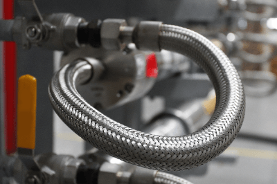
4. Blade Type

Instead of the structure of peaks and valleys, as described so far, this type has a tubular structure made of thin metal wires woven together like fibers of clothes.

Not only the above structures but also combinations of them are made. In many cases, a one-pitch or spiral type hose is reinforced on the outside with a braid type to create a double structure, making the hose both flexible and durable.

Other Information on Flexible Hose

1. Features of Flexible Hoses

Flexible hoses are characterized by their strength and pressure resistance, improved heat resistance, flexibility, ability to accommodate large displacements and effectiveness in preventing the transmission of equipment vibration.

  • High Performance
    By covering the outer surface of the flexible tube with a braided metal layer, strength, and pressure resistance are increased without compromising flexibility. Applicable fluids include gases such as air, various gases, and steam; liquids such as water, oil, solvents, chemicals, blood, and seasonings; and various powders. They can also be used in a wide range of temperatures, from low to high. Some can be used at several hundred degrees.
  • Capable of Handling Large Displacements
    Flexible hose blades can handle large displacements. These include hydraulic and pneumatic equipment with moving parts, robots, and automobile wheel brakes. They can also be used in seismic isolation equipment and underground piping to reduce damage caused by ground movement during earthquakes.
  • Vibration Countermeasures
    Flexible hoses are used in connection pipes for pumps, compressors, exhaust pipes, etc. Vibration transmission from equipment is suppressed.

2. Blade Type

When the blades are stainless steel, three main types are used.

  • Wire Blades
    Wire blades are made of stainless steel wire, with several wires bundled in parallel and braided into the outer surface of the tube. It has excellent flexibility and can absorb displacements that are frequently repeated. Also called round wire braid or wire braid.
  • Strip Braid
    Strip braid is made of stainless steel plates cut into strips and manually braided into the outer surface of the tube in the shape of a bamboo basket. Compared to wire braid, it has superior strength against internal pressure, but less flexibility, making it suitable for absorbing displacements with low repetition frequency. Also called plain wire braid or ribbon braid.
  • Twill Weave Braid
    The Twill weave braid is made by braiding the wire into flat plates, which are then woven into the outer surface of the tube. It has high durability and flexibility. It can be used for long lengths of piping but is the most expensive type of braid.
カテゴリー
category_usa

Flange Bolt

What Is a Flange Bolt?

Flange Bolts

A flange bolt is a screw that can be inserted without a washer. They are called flange bolts because there is a flange attached to the bolt. The advantage is that it is difficult to loosen because it has a seat attached, and it eliminates the need to assemble a washer.

There are two types of flange bolts: Type 1 and Type 2, with Type 1 having a flat washer flange and Type 2 having a tapered flange top.

Uses of Flange Bolts

Flange bolts are used in a wide range of applications, from consumer products such as automobiles to industrial products, such as various types of manufacturing equipment. Since flange bolts have a larger seating surface than hexagonal bolts, they do not sink into the bolt hole to be fastened, thus improving the appearance of the bolt.

In addition, the incorporation of washers is not necessary, which improves work efficiency. Therefore, this type of bolt is used when a clean appearance is desired or when work efficiency is to be improved.

Principle of Flange Bolts

The head shape and height of flange bolts are often determined at the discretion of the manufacturer, and many varieties exist.

In the case of M6 bolts, both Type 1 and Type 2 have the same “seat diameter 14.0 mm – hexagonal head 10 mm – head height 6.0 mm” and differ only in the surface shape of the seat surface. In some manufacturers’ standards, the back side of the washer may be processed with serrations (serrations). The serration allows the washer to bite into the fastening object easily, thereby improving stability.

In most cases, steel or stainless steel is used as the material. However, depending on the surrounding environment, titanium may be used. By appropriately selecting from a wide variety of flange bolts, stable and efficient fastening can be achieved.

How to Use Flange Bolts

Incorrect use of flange bolts can result in damage to nuts and equipment to be fastened. To prevent this, the following points should be taken into consideration when using flange bolts.

  • The fastening force must be within the allowable range.
  • Repeated force (due to vibration, etc.) applied to the flange bolt must be within the allowable range.
  • The pressure applied to the seating surface does not cause the fastening object to cave in.
  • The fastening force of the flange bolt shall not damage the fastening object.

Other Information on Flange Bolts

1. Materials and Surface Treatments of Flange Bolts

Flange bolt materials include steel, stainless steel, and titanium. Since each material has different strengths, it is necessary to fully consider these materials at the equipment design stage.

Electrical corrosion is also an important factor. If the material of the flange bolts differs from the material of the object to be fastened, electrical corrosion will occur. Particular attention should be paid to the case of aluminum and stainless steel.

Surface treatments for flange bolts include copper plating, black paint, trivalent chromate, uni chromate plating, hot-dip zinc plating, chromate plating, nickel plating, chrome plating, Parker, and necrotized. As mentioned above, selection is made according to electric corrosion protection, appearance, etc.

2. How to Prevent Flange Bolts from Loosening

Flange bolts may loosen over time. If flange bolts loosen and come off, there is a risk of a serious accident involving human life. Loosening can be caused by the following two factors:

  • Repeated vibration applied to the flange bolts
  • The heat generated in the flange bolt from the ambient temperature or from the object to be fastened

Tightening flange bolts too hard has the effect of preventing loosening, but there is a danger of the flange bolts breaking or the threaded hole tearing. Therefore, it is important to calculate the allowable range of fastening force at the time of design.

When retightening is used to prevent loosening, the bolts should be tightened according to the specified torque. Other measures to prevent loosening rather than retightening include the use of anti-loosening adhesives and double nuts. Although there is no guarantee that a machine will never loosen, it is necessary to take measures to prevent loosening to ensure the safe use of the machine.