カテゴリー
category_usa

Automatic Level

What Is an Automatic Level?

An automatic level refers to the measurement of the water level in a container, river, etc., or the height at which powder materials are stacked. Many measurement principles have been developed, and a variety of companies offer automatic level products. Some products combine the function of measuring the automatic level of the water level or height with the function of a switch to operate the appropriate equipment according to that level. Typical measurement methods include float, electrode, pressure, ultrasonic, laser, and capacitance.

Uses of Automatic Levels

Automatic levels are used in a wide range of applications from industry to public facilities, including industries that use tanks for storing liquids, facilities that manage rivers, etc., and water treatment plants. When selecting a method of automatic levels, it is necessary to consider the accuracy and detection speed of the measurement, whether the object to be measured is suitable for the measurement method, durability in the operating environment, ease of installation, and ease of maintenance.

The following are examples of automatic levels in use:

  • Measuring the remaining volume in a water storage tank
  • Measuring the degree of mixing in a chemical plant
  • Control of water levels in dam management facilities

Principles of Automatic Levels

The following is a description of the measurement principles of automatic levels, divided into the typical measurement principles: float, electrode, pressure, ultrasonic, laser, and capacitance.

  • Float Type
    A float with a built-in magnet is placed on the water’s surface, and its movement is measured by the magnetic force generated by the magnet.
  • Electrode Type
    Several electrode rods of different lengths are placed perpendicularly on the surface of the water, and the difference in the current-carrying capacity of the electrodes in the liquid and the air is used to determine roughly how much the automatic levels are. The measurement accuracy is determined by the number of electrodes.
  • Pressure Type
    The level is estimated by installing a pressure gauge at the bottom of the tank and measuring the amount of pressure exerted by the liquid. The gauge must be installed before filling the tank with liquid.
  • Ultrasonic Type
    The level is measured by irradiating ultrasonic waves toward the liquid surface and measuring the time it takes for the ultrasonic waves to reflect to the liquid surface. This is a non-contact measurement method.
  • Laser Type
    The level is measured by irradiating a laser beam toward the liquid surface and measuring the change in phase of the returned light when the laser beam reflects off the liquid surface. This is a non-contact measurement method.
  • Capacitance Type
    Level is estimated by placing electrodes in the air and the liquid, and measuring the difference in capacitance between the liquid and the air due to the difference in level.
カテゴリー
category_usa

Rework Station

What Is a Rework Station?

A rework station is a device that can perform soldering and desoldering in a single unit and can also replicate soldering operations that have been conducted previously.

The rework station is a box-equipped device with nozzles for soldering and desoldering. It can supply hot air through nitrogen gas as well as heat from electricity.

Reproducibility is crucial in rework stations, and specific points on the board’s surface can be temperature-measured to ensure reproducible process conditions.

Uses of Rework Stations

Rework stations are available in multi-station versions capable of performing not only soldering but also desoldering and SMD rework.

Applications include R&D, process development, prototyping, and production environments.

They enable highly reproducible soldering in applications ranging from small and medium PCBs to large BGAs.

Principles of Rework Stations

Some rework stations have reduced power consumption, as low as 140 W, resulting in stress-free component removal on multilayer boards and shorter operation times.

The new nozzles can also be used for extremely small land diameters, narrow spaces, and flat terminals, as encountered in miniaturized cellular phone substrates.

Nitrogen gas flows evenly between the nozzle assembly and the tip, enveloping the entire tip. This prevents oxidation of the tip and solder, enhancing the preheating effect.

This oxidation prevention and preheating effect can also improve soldering defects such as bridging, icicles, and soldering failure due to insufficient heat capacity.

Precise removal of residual solder in an inert atmosphere is possible, facilitating the removal of molten solder from the board in a single step with a powerful vacuum without disturbing the pad or solder resist.

After the residual solder is removed, the BGA and CSP can be reused by restoring the solder ball arrays with BGA or CSP components to the required specifications, saving time and money.

カテゴリー
category_usa

Relay Box

What Is a Relay Box?

A relay box is a device that contains several relays, which are electrical components. It consists of a box-like case that houses these relays, organizing wiring and facilitating their protection and management.

Its role also includes protecting the relays from external mechanical damage and environmental conditions.

Uses for Relay Boxes

Relay boxes are used in various industries and applications, including:

1. Automotive Industry

In the automotive industry, relay boxes are used in engine control systems and electronic control units (ECUs). They play a role in controlling the engine’s ignition and fuel injection systems, providing signal passing and protection functions.

2. Industrial Equipment Control

Relay boxes are employed in factory and manufacturing plant control systems. They are instrumental in controlling production lines and machines, and in managing the wiring of control signals.

3. Building and Housing

These boxes are used for controlling lighting systems and HVAC (heating, ventilation, and air conditioning) systems. Relay boxes allow for centralized control of multiple lighting and power sources. They are commonly used in office buildings for centralized monitoring controllers.

4. Automatic Control System

Relay boxes are sometimes part of automatic control systems, such as for automatic door and elevator control, as well as for controlling traffic signals in urban areas.

Principle of Relay Boxes

Relay boxes typically consist of the following components:

1. Box

The box-like case houses the relay and other electrical components, made from durable materials to protect its contents. It typically includes ventilation holes and wire entry ports.

2. Relay

The main component is the relay itself, an electrical part that receives and outputs signals to control machines. Relays are categorized into contact relays, which mechanically operate contacts to output a signal, and non-contact (solid-state) relays, which use semiconductors for signal output without physical contact.

3. Connection Terminal

These terminals connect the box to external signals and power supplies. They include input terminals for control signals and output terminals to transmit these signals to other devices or circuits.

4. Wiring

Wiring connects relays to other electrical components, establishing paths for control signals and power, ensuring proper relay operation.

How to Select a Relay Box

Consider the following when selecting a Relay Box:

1. Electrical Requirements

Assess the current and voltage requirements of your circuit. Ensure the relay and terminal components match these requirements to prevent issues like relay burnout.

2. Types of Relays

Choose the appropriate relay type (terminal relay, solid-state relay, etc.) based on the operating environment and application. The type of relay can influence the size and functionality of the relay box.

3. Size and Mounting Method

Consider the space available and the preferred mounting method (wall mount, DIN rail mount, etc.). Select a relay box that fits these criteria in terms of size and mounting options.

カテゴリー
category_usa

Linear Feeder

What Is a Linear Feeder?

A linear feeder is also called a short feeder or straight feeder. Hopper feeders, ball feeders, and linear feeders (chute feeders) are sometimes collectively referred to as parts feeders.

Parts feeders are machines that feed workpieces (parts and components) by vibrating them and aligning them in a fixed orientation and posture.

Linear feeders are small vibrators that vibrate a chute (rail or trough).

The length of the chute and the weight of the workpiece must be taken into consideration when selecting the feeder so that the feed rate does not slow down.

There are various types of linear feeders, but the most common types are the fixed type, rubber foot type, and plate spring type.

Uses of Linear Feeders

Parts feeders, including linear feeders, feed large quantities of workpieces (parts and components) to the next process machine (assembly machine, packaging machine, inspection machine, etc.) in the same direction and orientation at once by using the vibration of the bowl and the guidance of the attachments.

It is often used in conjunction with automated systems such as assembly machines, packaging machines, cooperative robots, and inspection machines.

Compared to cases where parts are fed manually, linear feeders dramatically increase not only the speed of work but also the accuracy of work, leading to improved productivity.

Principle of Linear Feeders

Although it is possible for linear feeders to have vibration tunnels, etc., originating from the lack of strength of the installation site, there are types of linear feeders that stabilize vibration even on a desk.

If a variable frequency controller is used for the linear feeders, spring adjustment and core gap adjustment are not required.

Installation and positioning have also been simplified, making it dramatically easier to use.

In addition, the maximum chute weight and maximum overhang length have been increased to allow for a wider range of possible applications.

In addition to the increased power, the smaller size and lighter weight also make any combination of conditions possible.

The low reaction force and plate spring vibration isolation type of linear feeders is plate spring vibration isolation type low reaction force linear feeders with even lower floor reaction force than the conventional product.

The structure of the drive unit has been improved in every detail, enabling even lower reaction force and smoother and more accurate parts feeding.

Since the linear feeders vibrate in the middle band of the parts feeder frequency (full wave and half wave), no vibration interference occurs when the linear feeders are used in combination with a parts feeder.

Smoother parts feeding occurs as a result of a more uniform vibration angle across the chute.

Since it is driven near resonance, sufficient amplitude can be obtained even with less current, i.e., less power consumption.

カテゴリー
category_usa

Halogen Heater

What Is a Halogen Heater?

A Halogen heater is a generic term for a heater that heats an object by applying electric power to a filament and using electromagnetic waves in the near-infrared to far-infrared regions generated during the heating process.
These heaters use radiation heating and emit red to white light because they include wavelengths in the visible region. They are characterized by uniform heating performance over a wide area and high responsiveness because they do not require a medium for heat transfer.
There are several types depending on the filament type and structure. Demand for lamp heaters has been increasing in recent years due to their high energy efficiency.

Uses of Halogen Heaters

Because of their radiation characteristics, lamp heaters are good at heating large areas uniformly, and are often used for heating flat objects. Typical examples are:
Drying processes in the production of semiconductors and flat panel displays, ink drying for printed materials, and in-line food drying.
It is also used for heating corrosive chemicals that are difficult to heat directly, and for heating equipment and food products.
Because they use near- to far-infrared rays, they are not suitable for heating transparent objects that are transparent to such rays.

Principle of Halogen Heaters

Applying electric power to a filament generates electromagnetic waves in the near- to far-infrared region, and the energy is used to heat an object in a non-contact state.
Filaments made of tungsten, carbon, iron-chromium-aluminum, nickel-chromium (nichrome), etc. are used, and the filament temperature reaches 2500-3000℃ (4,532-5,432°F).
If the filament is in contact with the atmosphere in such a low-temperature range, a rapid oxidation reaction occurs, resulting in wire breakage and thinning, which shortens the life of the filament.
Therefore, they are encapsulated in quartz glass tubes filled with vacuum or inert gas. Because of this structure, long, thin, cylindrical products are common, but halogen lamp heaters in the shape of a bare bulb are also available.

When heating a flat object, multiple halogen heaters must be arranged to ensure that the radiant energy evenly covers the object.
Unlike direct heating or ambient heating, if the shape or structure of the object is such that the radiant energy is blocked, the shadowed area will not be heated, making it unsuitable for some shapes of objects.
Therefore, it may not be suitable for some shapes of objects to be heated.

The object can be heated up to 1500°C (2,732°F), but the element must be set at 1000°C (1,832°F) or higher because the radiant energy is low at low temperatures below 500°C (932°F). The heating temperature of the object can be increased up to 1500°C, but the element must be set at 1000°C or higher because the radiant energy is low at temperatures below 500°C.
Although the energy efficiency is high, the power requirement is high for the reasons mentioned above, so it is not well suited for low-power, low-temperature heating applications.
In addition, if dirt or other contaminants adhere to the quartz tube bulb on the exterior, the dirt will be heated and the temperature distribution on the exterior surface will change significantly locally, which may cause damage.

カテゴリー
category_usa

Raman Microscope

What Is a Raman Microscope?

A Raman microscope (or Raman microscope) is a measurement instrument that combines a Raman spectrometer and an optical microscope.

It allows non-destructive analysis of detailed information on materials such as chemical structure, intermolecular interactions, and crystallinity. By combining a Raman microscope with a Raman spectrometer, it is possible to observe an object under the microscope and measure selected points, or to obtain an image visualizing the distribution of composition.

Uses of Raman Microscopes

Since Raman spectroscopy is based on chemical bonding, the following information can be obtained by measurement

  • Chemical structure
  • Phase, polymorphism
  • Strain
  • Impurities, contamination

Since Raman spectra are unique to each substance, they can be used to quickly identify a substance or distinguish it from other substances. Raman microscopes can also be used to analyze many different samples. In general, it is not suitable for the analysis of metals and alloys, but for the analysis of:

  • Solids, powders, liquids, gels, slurries, and gases
  • Inorganic, organic, and biological materials
  • Pure chemicals, mixtures, and solutions
  • Metal oxides and corrosion

Typical examples of where Raman microscopes are used include:

  • Characterization of pigments, ceramics, and gemstones in the fields of art and archaeology
  • Evaluation of the structure and purity, defects, and disorder of carbon material nanotubes
  • In chemistry, structure, purity, and reaction monitoring
  • In the life sciences, single cells and tissues, drug interactions, and disease diagnosis

Structure of Raman Microscopes

Raman-Microscopes_ラマン顕微鏡-1

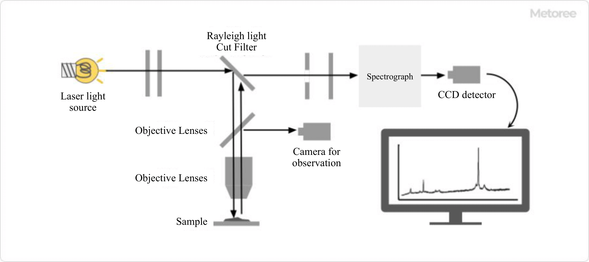
Figure 1. Structure of Raman microscope

The Raman microscopes are measuring instruments that combine a Raman spectrometer and a microscope.

Irradiated light from a laser source is guided to the sample through the objective lens of the microscope and irradiated onto the sample. The scattered light generated from the sample is focused by the objective lens, and only the Raman scattered light is detected through a Rayleigh light cut filter.

Principle of Raman Microscopes

Raman-Microscopes_ラマン顕微鏡-2

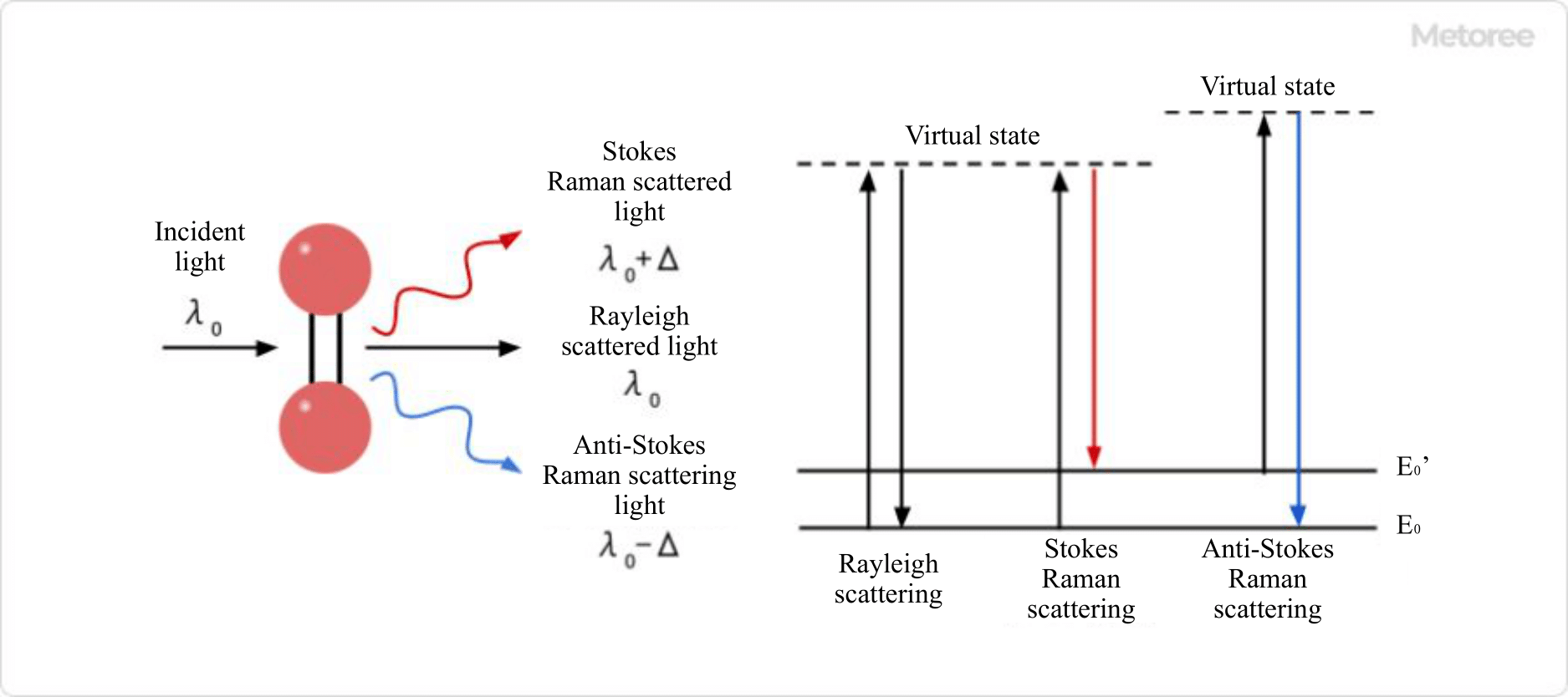
Figure 2. Raman scattering

When a material is irradiated with light, a scattering phenomenon occurs. Most of the scattered light is Rayleigh scattered light with the same wavelength as the irradiated light, but some scattered light with slightly different wavelengths from the irradiated light is included, and this scattered light is called Raman scattered light.

There are two types of Raman scattering light: Stokes scattering light, which has a wavelength longer than that of the irradiated light, and anti-Stokes scattering light, which has a shorter wavelength.

Raman scattering light is produced as a result of the interaction of irradiated light with a material, and the difference in wavelength between Rayleigh scattering light and Raman scattering light corresponds to the energy of molecular vibration of the irradiated material. It is known that only Raman-active vibrational modes are responsible for Raman scattering, and it is possible to infer or simulate Raman-active vibrational modes from molecular structures.

A similar analytical instrument that uses molecular vibration is the infrared spectrophotometer, but there are differences in the molecular vibrations that can be measured, making it a complementary analytical instrument.

Different types of molecules and different bonding states produce different molecular vibration energies, resulting in different Raman spectra. Substances can be identified by comparing the peak positions and relative peak intensities of the Raman spectra with those of known substances. It is also often used for qualitative analysis by interpreting the following:

  • Peak position
    Chemical bond information
  • Peak Shift
    Information on intermolecular interactions, stress, and strain
  • Spectral waveform
    Molecular structure information, crystal structure differences
  • Half value width
    Difference between crystalline and non-crystalline

Quantitative analysis is also available by utilizing the fact that the intensity of the spectrum is proportional to concentration.

Other Information on Raman Microscopes

1. Cautions for Raman Microscopes

Raman-Microscopes_ラマン顕微鏡-3

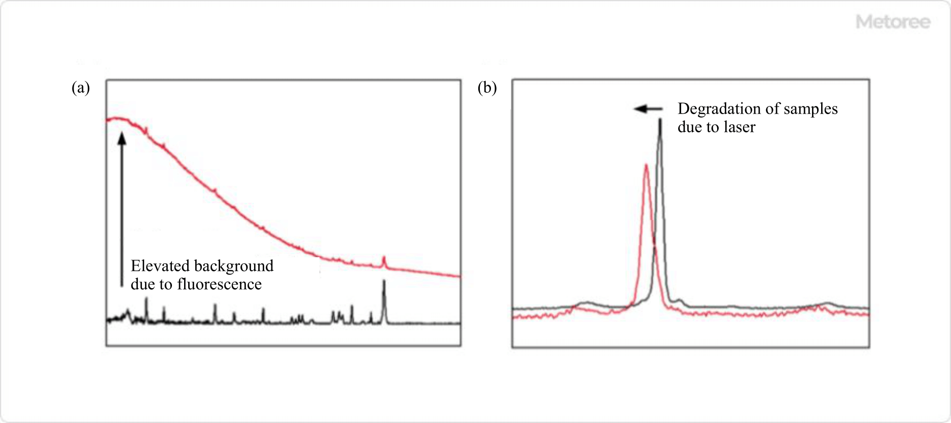
Figure 3. (a) Effect of laser irradiation on fluorescence generation (b) Degradation due to laser irradiation

Since Raman scattering light is weaker than Rayleigh scattering light, a certain intensity of laser light is necessary, but the laser light may cause problems. If the wavelength of the laser light overlaps with the absorption region of the molecule to be measured, the molecule will fluoresce and the background of the Raman spectrum will increase, burying the spectrum to be obtained.

To avoid this, it is necessary to take measures such as adjusting the exposure time and other measurement conditions, adjusting the depth of focus, narrowing the spectral slit, and using a confocal filter (DSF). Other ways to suppress fluorescence include changing the laser source.

For organic materials, fluorescence often occurs when using the common 532 nm laser light, so a longer wavelength laser light, such as 785 nm, is sometimes selected. However, care must be taken when changing to a longer wavelength laser light, as the sensitivity of some monochromators and detectors may decrease drastically.

If the material to be measured is organic or carbon material, depending on the intensity and duration of the laser light, the material may be “burnt” and degraded. To prevent degradation of the measured material, the measurement conditions can be adjusted by lowering the laser intensity or shortening the exposure time.

In addition, some carbon materials are photo-reactive, meaning that they react to the irradiated laser light. Such materials can be handled by adjusting the measurement conditions in the same way, or by changing the wavelength of the laser light to suppress the photoreaction.

2. New Raman Microscopes Technology

Various techniques have been developed to improve the sensitivity and resolution of Raman microscopes.

Surface-enhanced Raman (SERS) and Tip-enhanced Raman (TERS) make use of a phenomenon called localized surface plasmon resonance that occurs at metal surfaces, allowing measurement of larger intensity of Raman scattered light and higher sensitivity and spatial resolution.

Coherent Anti-Stokes Raman Scattering (CARS) and Induced Raman Scattering (SRS) are types of nonlinear Raman scattering, in which two different wavelengths of light are used simultaneously to obtain spectra with signal intensities that are many orders of magnitude higher.

Other techniques have also been developed that allow Raman imaging to be performed more quickly, such as using a beam splitter to obtain a Raman spectrum in a linear or planar form with a single laser pulse.

カテゴリー
category_usa

Line Laser

What Is a Line Laser?

A line laser is a device that draws a laser line in space to define the position where work is to be performed.

It is mainly used in construction sites and interior decoration work. It is non-destructive and leaves no trace. To direct the laser to the exact location, the level must be ensured even if the ground on which it is to be installed is tilted.

There are two types of line lasers: gimbal and electronically straightened. Some products have two lasers, some have several, and some can even draw a line to the ceiling.

Applications of Line Lasers

Line lasers are used at construction sites for factories, facilities, and homes to designate where equipment is to be brought in and where structures are to be installed. They are also useful in interior work to designate points where holes are to be drilled.

When selecting a line laser, it is important to consider the selection of the leveling mechanism, the number of lasers, and whether the line laser is suitable for the environment in which it will be used. Attention should also be paid to the color of the laser, as its legibility varies depending on the environment.

Principle of Line Lasers

Line lasers consist of a leveling mechanism and a laser output unit. The laser output section uses a semiconductor. When energy is given to a semiconductor, it enters an excited state and emits light as it returns from the excited state to the ground state.

When an atom inside a semiconductor in an excited state emits light, this light is irradiated onto the surrounding excited atoms. The surrounding excited atoms then also emit light in a phenomenon called induced radiation. This is the principle behind the intense output of laser light.

The light is amplified by the mirror plate or junction, and the light is emitted as a laser. The aforementioned induced radiation emits light of the same wavelength and phase, resulting in highly directional light output.

1. Gimbal Type

The gimbal type has a built-in pendulum, which vibrates to determine the center point of the earth and to level the instrument. Because of its simple principle of operation using gravity, the accuracy is not affected by outside temperature or pressure, as is the case with the electronic reference system (see below).

However, care must be taken in places where there is vibration, as the pendulum oscillation is unstable and the line is not stable. It is also vulnerable to dust and other foreign matter.

2. Electronic Canonical Type

The electronic canonical type incorporates a container with liquid and air bubbles and measures the position of the bubbles to level the line. The sensor that measures the position of the bubbles is called a canonical sensor. Based on the sensor value acquired by the canonical sensor, the horizontal position is calculated using a board inside.

Because of the above principle, the advantage of this type of sensor is that it is more resistant to vibration than the gimbal type. However, it should be noted that under high temperatures, a large amount of air bubbles may be generated and the canonical sensor cannot acquire accurate sensor values. In addition to temperature, it is also affected by pressure.

Other Information on Line Lasers

1. Magnitude and Color of Laser Light

The size of the laser beam is determined by standards, and line lasers use a light size that does not cause immediate exposure to the human eye. There are two laser colors: red and green.

Red light is difficult to see outdoors, so its main application is for line-laying indoors or in dimly lit sites. The green light is easier to see outdoors, so it is also used for outdoor line marking applications.

2. Photodetector

A photodetector is a device that emits sound in response to light. By shining the receiver on the area where the line is to be laid out, the operator can confirm where the line is drawn by judging by the sound. This device is useful in situations where light is difficult to see, such as bright sites in direct sunlight.

カテゴリー
category_usa

Line Heater

What Is a Line Heater?

A line heater is a specialized heater that uses the light from a halogen lamp to heat objects in a linear fashion. Capable of heating objects to over 1,000 °C, these heaters are efficient, converting over 85% of input power into infrared radiation. Utilizing a low heat capacity filament, such as tungsten, they offer rapid temperature adjustment in a non-contact manner, ideal for clean environments and various heating atmospheres.

Uses of Line Heaters

Line heaters are employed in various manufacturing processes due to their non-contact nature and precise temperature control. Key applications include semiconductor manufacturing, resin material processing, and heating specific areas of mechanical materials. In semiconductors, they are used for oxide film formation and activation post-ion implantation. Automotive manufacturing utilizes them for thermoforming steel sheets. Other uses include solar cell module processing, vacuum or high-purity gas atmosphere heating, soldering solar panels, and as heat sources in conveyor lines.

Principle of Line Heater

Halogen lamps in line heaters contain halogen gases like iodine or bromine, along with nitrogen or argon. A tungsten filament inside emits light upon electrical stimulation. The interaction between evaporated tungsten atoms and halogen gas forms tungsten halide, which dissociates near the filament, ensuring stable operation. Infrared light from the filament is focused onto the object using mirrors, allowing for high-intensity, non-contact infrared heating.

Types of Line Heaters

Line heaters are categorized by their heating mechanism:

1. Halogen Line Heater

These heaters focus halogen lamp light using mirrors or collimated light, suitable for factory line heating, semiconductor manufacturing, and fusing plastic rolls. Various mirror types provide different focal lengths and heating intensities. Cooling methods include natural, air, and water cooling.

2. Line Heater for Piping

These heaters heat air, gases, liquids, and steam in piping systems. Available in indoor, outdoor, and terminal cooling types, they integrate directly with compressors, fans, blowers, and boilers.

Heat exchange occurs as fluid flows through the heater, with options for temperature control and overheating prevention. Common uses include enhancing the heating capacity of water source heat pump systems and hot water boilers and raising hot water temperature for air conditioners.

カテゴリー
category_usa

Molding

What Is Molding?

Moldings

Molding refers to the process of pouring melted resin into a metal mold or applying pressure to a powder to form it. Injection molding is a common method of manufacturing plastics, and injection molding equipment is available from various companies. A molding technology is also used in the manufacturing process of semiconductors to protect semiconductor chips, making it an indispensable technology in today’s industry.

Uses of Moldings

Moldings are used in a variety of industries, including plastic manufacturing sites, semiconductor manufacturing sites, and resin product manufacturing sites. Protective coatings on plastic bottles and semiconductor chips are the main destinations for moldings. When selecting equipment for molding, it is necessary to consider manufacturing speed, molding accuracy, power consumption, and the materials of molding that are supported. Especially for molding equipment used in the manufacturing process of precision equipment, its components, and semiconductors, it is necessary to select high-precision equipment.

Principles of Moldings

The following is an explanation of the principle of operation of moldings, using injection moldings of plastic and semiconductor moldings as examples, which are the main applications of moldings.

  • Injection Molding
    Injection molding is used to mold plastic bottles and plastic containers. The resin melted by heating is poured into a mold, which is then cooled to form the resin into the shape of the mold. For general continuous injection moldings, there is a device that removes the mold from the die, allowing for continuous moldings.
  • Semiconductor moldings
    Semiconductor moldings are performed to protect semiconductor chips from oxidation and dust adhesion by surrounding them with resin after the wiring has been completed. A mold is placed over the semiconductor chip, and a small amount of melted resin is poured into the mold and allowed to cool before molding. The resin must be poured at a temperature that does not damage the semiconductor, and solidified in a high-precision mold so that no burrs or other defects are generated.
カテゴリー
category_usa

Mesh Pallet

What Is a Mesh Pallet?

Mesh Pallets

You may have seen boxes made of metal mesh used to transport goods in warehouses or at construction sites.

These metal mesh boxes are called mesh pallets and are also referred to as mesh boxes, mesh containers, or mesh baskets due to their box-like shape. They are sometimes known as palletina or mesh pallets.

The basic structure of a mesh pallet, as shown in the image above, consists of metal mesh plates with an opening on the top surface opposite the part that serves as the conveyance platform.

The box-like structure of a mesh pallet enables it to be used for transporting, storing, and organizing cargo by placing the cargo inside.
Because they are made of metal mesh, they are lightweight and durable, making them extremely convenient transportation containers that can serve as pallets for transporting goods, containers for transporting and storing goods, or racks for displaying goods as they are.

Specifications of Mesh Pallets

Mesh pallets are available in various specifications. The size is determined by height, width, and depth, and all manufacturers offer a similar lineup.

There are three basic types of mesh pitch sizes for the metal mesh that makes up the mesh: 25 x 50, 50 x 50, and 50 x 100 (mm). The finer the pitch, the stronger the mesh, but finer pitches also result in increased weight and cost, which can be a disadvantage.

The basic structure is a box with an open top, but some types have foldable sides and can be folded flat.

This foldable type is very convenient because it can be folded and stacked for storage when not in use. Additionally, it is relatively easy to move multiple mesh pallets when they are folded.

Some folding types have a design that allows stacking the legs on the bottom of the conveyor stand to ensure stability when stacked. Others feature an insertion slot for a forklift claw on the underside of the platform, while some can be used with a hoist crane. Furthermore, certain types are designed for crane lifting, including those with a top cover and those with a lifting bracket.

In addition, some types are equipped with casters on the conveyance platform. The advantage of casters is that they allow easy movement by simply pushing, with usability varying depending on the position and number of casters.

However, the presence of casters reduces stability, so there are height limitations when stacked for storage.

Conclusion

Mesh pallets are highly versatile cargo transport containers suitable for use as pallets, containers, or racks. The ability of a single mesh pallet to serve three different purposes can contribute to cost reduction. Their box-shaped design makes them particularly well-suited for transporting heavy loads, regardless of the type or shape of the load, such as metal, food, books, and more.

In addition to basic characteristics such as dimensions, mesh size, and load capacity, mesh pallets come with various other features, including foldability, presence of casters, and suspension capabilities. It is important to select and use mesh pallets based on the product to be transported, intended use, operational efficiency, and budget.

Although mesh pallets are plated, they can develop scratches from forklift nails during transportation, leading to gradual rusting. Therefore, it is recommended to use new pallets for safe transportation without contaminating the cargo.