カテゴリー
category_usa

Micro Syringe

What Is a Micro Syringe?

Micro Syringes

A micro syringe is a precision laboratory tool designed for injecting very small volumes of liquid samples into analytical instruments such as liquid chromatographs (HPLC) and gas chromatographs (GC). These syringes range in volume from 0.1 µL to 500 µL and can be constructed from materials like glass or metal, necessitating careful selection based on the specific analytical requirements and instrumentation.

With the advent of autosamplers, which automate the sample injection process, the manual use of micro syringes has seen a decline. However, they remain indispensable for applications requiring precise manual control over sample volume.

Uses of Micro Syringes

Micro syringes are extensively employed in chromatography for the precise injection of samples into chromatographs. Depending on the instrument’s setup, they can be used with both autosamplers and manual injectors, offering flexibility in handling complex sample matrices or minute sample volumes that are challenging for automated systems.

Principle of Micro Syringes

Using a micro syringe involves several critical steps to ensure accuracy and prevent contamination:

  • Inspect the needle for damage before use.
  • Rinse the syringe with the sample to be injected to prevent cross-contamination.
  • Aspirate slightly more sample than needed, then expel air bubbles before injection.
  • Inject the sample carefully into the chromatograph, ensuring the needle is fully inserted and air bubbles are minimized.
  • Rinse the syringe post-injection to avoid carryover effects.

Types of Micro Syringes

Micro syringes are categorized by their needle tip design, tailored for specific chromatography applications:

  • Liquid Chromatography Syringes: Feature a needle with a right-angle tip.
  • Gas Chromatography Syringes: Have a sharp-angled needle tip to penetrate the septum without damage.

Using the incorrect syringe type can cause damage to the chromatograph or impede sample injection.

Structure of Micro Syringes

A micro syringe comprises a barrel, a plunger, and an attached needle. The plunger’s design, especially in syringes of low volume, includes a guide to ensure consistent volume collection and to prevent damage from misaligned plunging. The broad range of available volumes allows for the selection of a syringe that matches the analytical task at hand precisely.

カテゴリー
category_usa

Blind Flange

What Is a Blind Flange?

Blind Flanges

A blind flange or blank flange is a type of joint used in piping and is a flange that stops the flow of the fluid at the end of a pipe. Generally, “closed flange” and “blind flange” are used as synonymous terms.

Uses of Blind Flanges

Blind flanges are used to temporarily or permanently stop the flow of fluid at the end of a pipe by attaching it to the mating side of the pipe end flange.

To select blind flanges, the material, pressure resistance, size (inside and outside diameter), etc., are selected based on the type of fluid, pressure, temperature, flow rate, etc. Basically, the same specification, material, and size as the flange installed on the mating side should be selected.

Although valves and other devices may be used to stop the flow of fluid, blind flanges are used to close the opening at the end of pipe and blind flanges completely. This prevents foreign matter from entering through the opening and enables the pipe to be closed without being exposed to the atmosphere.

Principle of Blind Flanges

The principle of blind flanges is exactly the same as that of ordinary piping flanges: the flange surfaces to be connected are tightly sealed by adhering to each other. The difference from a normal piping flange is that the flange has no holes for pipes, but only holes for bolts.

As with ordinary piping flanges, a gasket is generally inserted between the flanges to increase the adhesiveness of the flanges. The flanges are tightened together with bolts and nuts to increase and maintain the adhesion. In this case, the bolts and nuts must be tightened evenly.

For this reason, bolts and nuts are generally tightened diagonally rather than in sequence. It is also important to tighten the bolts and nuts at the specified torque value for the gasket material and bolt/nut. The tightening torque is gradually increased in diagonal order until the required tightening torque value is reached.
When used with high-temperature fluid, the tightening of the threads may loosen due to thermal expansion after the actual flow of high-temperature fluid. In such cases, the bolts and nuts must be re-tightened.

Although the material of the membrane flange varies depending on the fluid used, generally austenitic stainless steels such as carbon steel, SUS304 and SUS316, or carbon steel castings, are used. As mentioned above, the same material as that of the mating flange should be used.

Selection of the type, model, and material of the gasket to be inserted between the flanges is also important to improve and maintain sealing performance. Selection criteria are usually defined by various standards, and selection is based on the type of fluid, temperature, and pressure.

カテゴリー
category_usa

Metallograph

What Are Metallographs?

Metallographs, also known as projection microscopes or falling-glass microscopes, are a type of optical microscope.

In general, most of what is called industrial microscopy refers to metallographs. Although the name metallurgy is given to it, it is used to observe the surface of samples that are difficult for light to penetrate, such as metals, ores, ceramics, semiconductors, and so on.

Metallographs use light reflected from the sample to produce a magnified image. Similarly, a stereo microscope uses light reflected from a sample to obtain a magnified image.

Uses of Metallographs

Metallographs are used to observe metallographic structures and alloys, ceramics, semiconductors, plastic electronic components, rocks, and ores.

Specific applications are as follows:

  • Observation of changes in the state of raw materials before and after physical or thermal processing at metal casting, refining, metallurgy, etc.
  • Inspection of defects such as minute dents and scratches that cannot be seen with a stereo microscope at processing sites for plastics and semiconductor products, etc.
  • Quality control at production sites in the precision machinery industry, electrical and electronic industries, etc.
  • Research or education in metallography, mineralogy, etc.

Principle of Metallograph

Metallographs_金属顕微鏡-1

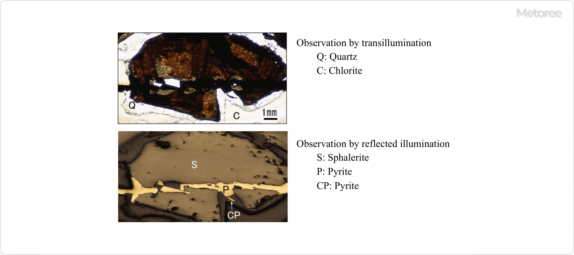
Figure 1. Images of the same field of view observed with transillumination and reflected illumination

The most significant difference between transillumination and reflected illumination observation is that areas that appear dark in transillumination appear bright in reflected illumination. Therefore, information that could not be seen with a biological microscope can be compensated for with a metallograph.

An ordinary optical microscope for observing microorganisms and cells is also called a transmission optical microscope because the light transmitted through the sample is magnified by the objective lens and eyepiece.

_Metallographs_金属顕微鏡-2.

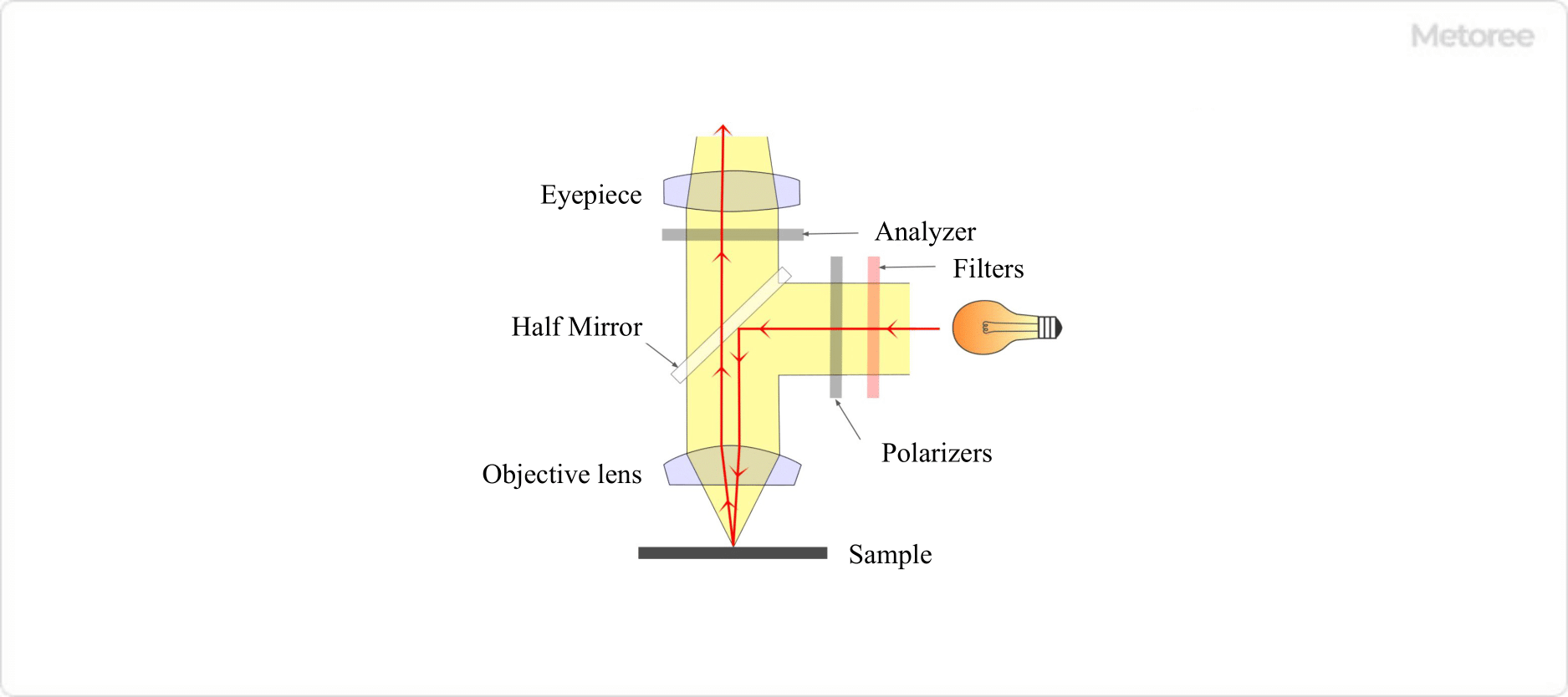
Figure 2. Illumination optics (Polarized light observation specification)

Metallographs are also a type of optical microscope and have the same general structure as biological microscopes, but they have a unique structure for observing specimens that light cannot penetrate at high magnification. In this optical system, light emitted from the light source is reflected by a half-mirror and reaches the sample for observation through the objective lens, and the reflected light from the sample is observed by the human eye through the objective lens and eyepiece.

How to Select a Metallograph

There are various types of metallographs, ranging from portable ones which can be relatively cheap to larger ones which can be expensive when options such as lens sets and imaging equipment are included.

When selecting a metallograph, it is important to first clarify the purpose of use. When making the actual selection, consider the following points:

  • If you prefer the sample surface to face downwards, or if you want to exchange samples quickly, choose an inverted type with the mirror body below the sample; otherwise, choose an upright type.
  • If you intend to observe polarization characteristics such as optical anisotropy of the sample, select a polarizing microscope that comes standard with a polarizing filter set.
  • If you also wish to perform transillumination observation, a microscope that can instantly switch between transillumination and reflection illumination with a single touch is optimal.
  • If you want to frequently take pictures and movies of the observed images, a trinocular type that allows binocular observation with a camera attached is most suitable.
  • If you want to move a sample precisely at a high magnification of more than 100x, select a stage that meets your purpose, such as a mechanical stage or an XY stage.

Other Information on Metallographs

1. Main Optical Filters

Metallographs are available with the same filters as biological microscopes to help you observe the optical properties of your samples in detail.

Color temperature conversion (LB) filters
The color temperature of a sample varies depending on the type of lamp used as the illumination source, so the color of the sample to be observed depends on the light source. In optical microscopy, the color of a sample is one of the most important factors to observe.

In order to correctly compare the color of a sample with the color described in literature, it is necessary to observe the sample at the same color temperature. Therefore, a color temperature conversion filter is used to achieve the same color temperature as sunlight, which is the most universal light source.

Color Correction (CC) Filters
Color correction (CC) filters are used to adjust the intensity of the three primary colors of light (red, green, and blue) or the three primary colors of color (cyan, magenta, and yellow).

Polarization Filter
Polarizing filters are a set of polarizers placed immediately after the light source (in front of the sample) and an analyzer placed between the sample and the eyepiece. The polarization filters are used to determine the change in polarization state when polarized light that has passed through the polarizer is reflected by the sample.

Since the polarization state changes depending on the crystal structure of the sample and other factors, the polarization filter can be used to determine the optical properties of crystals and the internal structure of polymers. 

2. Preparation of Samples for Metallograph

When observing with a metallograph, the specimen surface must be smooth and set so that the light from the objective lens enters the specimen perpendicularly. Microscopic observation with reflected light provides strong contrast in the case of scratches on the specimen surface, but it is often impossible to distinguish differences in the optical orientation of crystals or slight differences in composition.

Therefore, unless the surface is smooth without processing, the specimen may need to be cut and polished before observation, or an etching process may be required to make difficult-to-see microstructures easier to see.

Preparation of Polished Specimens

Diamond cutters and polishing equipment are used to cut and polish specimens to the appropriate size. In addition, special polishing flakes are required for mineralogical studies, for example, when it is necessary to switch between transmitted and reflected illumination observation. The creation of polishing flakes can be automated to some extent, but sufficient experience and knowledge are required for the creation of polishing flakes.

Metallographs_金属顕微鏡-3

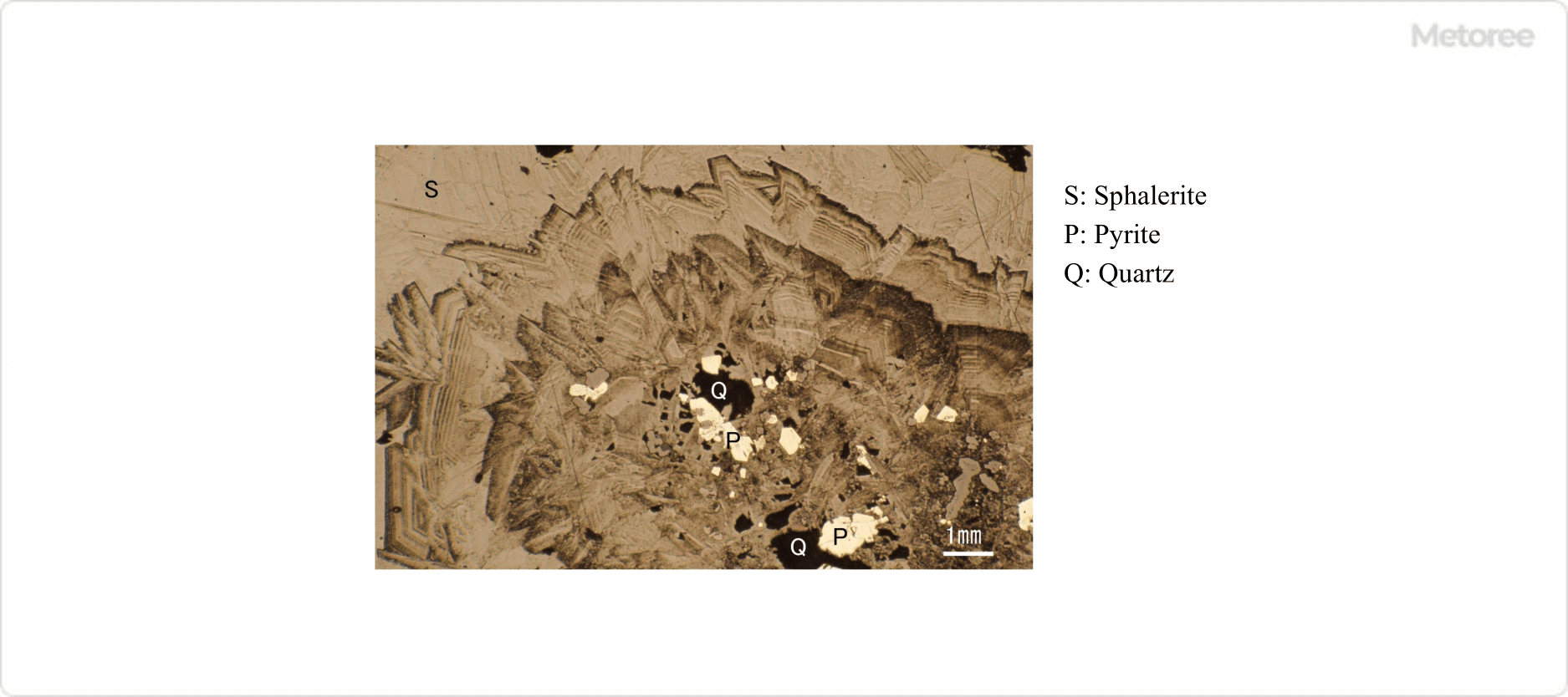
Figure 3. Growth pattern in sphalerite after etching with nitric acid

When grain boundaries or microstructures that should be present are not visible, etching of the sample surface can often solve the problem. There are two types of etching methods: chemical etching with acid and electrolytic etching.

カテゴリー
category_usa

Blind Flange

What Is a Blind Flange?

Blind Flanges

A blind flange, also known as a blank flange, is a fitting used in piping systems to terminate the flow of fluids. It is a type of flange that does not have a center opening, allowing it to effectively seal the end of a pipeline, duct, or other fluid transfer equipment.

Uses of Blind Flanges

Blind flanges are essential for creating a secure closure on piping systems, preventing the entry of foreign materials, and enabling easy access for inspection, cleaning, or modification. They find application in various settings including industrial plants, power generation facilities, and residential systems for emergency or temporary shutdowns.

Principle of Blind Flanges

The blind flange functions by creating a seal at the end of a pipe using a gasket placed between the flange and its mating surface. Bolts and nuts are then applied to clamp the flange in place, ensuring an even distribution of pressure to prevent leaks. The assembly must be tightened to a specific torque, often using a diagonal pattern, to ensure uniform sealing.

Types of Blind Flanges

The selection of blind flanges is based on factors such as the type of fluid, pressure, temperature, and flow rate. Key considerations include the nominal diameter, pressure rating, gasket seat type, and material of the flange:

  • Nominal Diameter: Matches the diameter of the piping system, ranging from 10A to 1,500A in JIS standards.
  • Nominal Pressure: Chosen based on the fluid pressure and temperature, with standards providing various classifications such as 5K to 63K for JIS and Class 150 to 2500 for ASME/ANSI.
  • Gasket Seat Types: Include full-face, flat-face, fitted, and groove types, selected according to the gasket design.
  • Material: Generally includes carbon steel and stainless steel, with specific alloys chosen based on environmental and operational requirements.

Other Information on Blind Flanges

Blind flanges adhere to several standards, including JIS, ASME/ANSI, ISO, and JPI, each specifying dimensions, materials, and performance criteria. Gasket selection is critical, with options ranging from joint seat gaskets to spiral wound and ring joint types, depending on the operational conditions.

1. Standard

Blind flanges adhere to several standards, including JIS, ASME/ANSI, ISO, and JPI, each specifying dimensions, materials, and performance criteria. Typical examples are as follows:

  • ASME/ANSI B16.5 Pipe Flanges and Flanged Fittings, NPS1/2 Through NPS24 Metric/Inch Standard
  • ISO 7005-1 Pipe flanges-Part 1: Steel flanges for industrial and general service piping systems.

2. Gasket

Gasket selection is critical, with options ranging from joint seat gaskets to spiral wound and ring joint types, depending on the operational conditions such as the temperature and pressure of the fluid. 

Joint Seat Gasket
Made of carbon fiber, blended with rubber and vulcanized rolled into a sheet, cut to fit the flange seating surface dimensions.

Spiral Wound Gasket
Made by overlapping a V-shaped metal hoop (thin metal sheet) and filler (tape-like sealing material) and forming it into a spiral shape. They have high sealing performance and are often used with high-temperature, high-pressure fluids.

Ring Joint
Metal gaskets made of mild steel, stainless steel, Monel, and other materials in two cross-sectional shapes: oval and octagonal. 

カテゴリー
category_usa

Digital Micrometer

What Is a Digital Micrometer?

Digital Micrometers

A digital micrometer is a type of micrometer used for measurements that require high-dimensional accuracy in the order of 1 micron.

Since the measured dimensions can be checked visually and instantly, it is actively used at manufacturing sites. It helps prevent misreading of the scale, as is the case with analog micrometers that directly read the scale.

The components are basically the same as those of the analog type, and the digital type is also inscribed with a scale.

Uses of Digital Micrometers

Micrometers are mainly used at manufacturing sites and for measuring parts that require high dimensional accuracy in units of 0.001mm. They are capable of even more precise measurements than calipers.

In addition, various types of micrometers are available for different applications. These applications range from basic O.D., I.D., and depth measurements to measuring the tooth thickness of spur gears and measuring narrow grooves. They can even measure the web diameter of drills. Micrometers are widely used in a variety of situations and for a wide range of applications.

Features of Digital Micrometers

The construction of digital micrometers is basically the same as that of analog micrometers. However, since they are digital, they have a power button, a button to set the zero point, and a button to hold the measurement.

Some digital micrometers are also equipped with a function that allows measurement results to be transferred to a PC or tablet, which contributes to the efficiency of operations.

However, since digitally represented dimensions may be misrepresented due to electrical problems, and incorrect values may be displayed, they are only for reference purposes and must ultimately be checked directly on the scale to confirm that the dimensions are correct.

In addition, since direct contact with the micrometer will cause the frame to warm up with body heat, making accurate measurement impossible, a micrometer stand must be used to hold the micrometer in place for measurement.

Furthermore, since it uses batteries, the risk of the batteries running out is a disadvantage.

カテゴリー
category_usa

Incremental Encoder

What Is an Incremental Encoder?

Incremental Encoders

An encoder is a type of electronic component that uses a sensor to detect the amount, direction, and angle of mechanical movement and output them as electrical signals.

Encoders are divided into incremental encoders and absolute encoders, depending on the detection method.

An incremental encoder is an encoder that can measure the amount of change in position/rotation after the power is turned on. An absolute encoder can detect the absolute position/rotation from the origin even after the power is turned off.

With an incremental encoder, the absolute position cannot be determined unless a homing operation is performed after the power is turned off. The difference between incremental encoders and absolute encoders is whether this homing is required or not.

Uses of Incremental Encoders

Incremental encoders are used as position/speed detectors in various machines, including:

  • Machine tools
  • Semiconductor manufacturing equipment
  • Mobile robots and automated guided vehicles
  • Elevators
  • Automobiles

Incremental encoders are often used as a component of motors. The encoder detects the direction and angle of rotation of a rotating shaft and uses the information for position and speed control of the motor.

Principle of Incremental Encoders

1. Incremental Encoder Method

Incremental encoders are divided into optical encoders and magnetic encoders, depending on the electrical detection principle.

  • Optical Encoder
    A light source such as LED is passed through a slit. The pulse of the light source passing through the slit is detected by a light-receiving element. This method is characterized by high accuracy and compatibility with high magnetic fields.
  • Magnetic Encoder
    A permanent magnet is attached to the end of a rotating shaft. The magnetic field is detected by a Hall element and converted into a rotation angle. It is resistant to environments subject to vibration, shock, and dust.

2. Optical Incremental Encoder Configuration and Position Detection Principle

The position detection principle of incremental encoders is explained using an optical encoder as an example.

An optical encoder mainly consists of a light emitter, a light receiver, and a disc (scale).

The disc (scale) has a slit engraved on it. As the disc rotates, light emitted from the light emitter repeatedly passes through and is blocked by the slit, thereby generating light pulses on the photosensor. The number of pulses output corresponds to the amount of movement of the slit, and the amount of movement can be detected by the number of pulses counted.

The slit is engraved with three types of slits: phase-A, phase-B, and phase Z. The light-receiving element detects these three types of pulses.

  • A-phase, B-phase
    The number of slits determines the encoder’s resolution; the B-phase is offset from the A-phase by a quarter cycle (90°).
  • Phase Z
    The number of rotations of the encoder can be counted by detecting the pulses of phase Z.

Figure 1. Optical incremental encoder configuration

Figure 1. Optical incremental encoder configuration

There are two types of encoders: linear encoders, which detect linear movement, and rotary encoders, which detect rotational angles. Figure 1 uses a rotary encoder as an example, but the principle itself is the same for a linear encoder.

In a rotary encoder, slits are engraved on a disk-shaped disk, whereas in a linear encoder, slits are engraved on a rectangular-shaped scale like a ruler.

3. Principle of Detecting Direction of Rotation for Incremental Encoders

The rotational direction of FWD/REV can be detected by the order of the rising edges of the phase A and B pulses.

In FWD rotation, the rising edges of the phase A and B pulses are:

Phase A → Phase B → Phase A → Phase B → …

Phase A→Phase B→Phase A→Phase B→…

Figure 2. Detection order of phases A and B during forward rotation

Figure 2. Detection order of phases A and B during forward rotation

In REV, the rising edges of the pulses of phases A and B are:

Phase B → Phase A → Phase B → Phase A → …

Phase B -> Phase A -> Phase B -> Phase A -> …

Figure 3. Detection order of phases A and B during reverse rotation

Figure 3. Detection order of phases A and B during reverse rotation

Since phases A and B are offset by 1/4 cycle, the direction of rotation can be determined by the order of the rising edges of the respective pulses.

Other Information on Incremental Encoders

Main Specifications of Incremental Encoders

The main specifications that can be used as an indicator when selecting an incremental encoder are as follows:

  • Resolution
    Number of pulses per revolution.
  • Power Supply
    Power supply for encoder operation.
  • Output Signal Phase
    There are two types: one that outputs phase A, B, and Z, and the other that outputs phase A and B.
  • Output Form
    Pulse output form, such as open collector, line driver output, etc. Some encoders will output position via serial communication.
  • Allowable Speed
    This is the upper rotational speed limit that the encoder can detect.
カテゴリー
category_usa

Flow Cell

What Is a Flow Cell?

A flow cell flowmeter is a type of orifice flowmeter that measures flow rate by generating differential pressure by installing an orifice in the piping. Water or air flows through the piping, and the value is measured and indicated by a float installed in the tributary flow.

Compared to other flow meters, orifice flow meters have a simple structure and are easy to install. However, they are not suitable for measuring substances with significantly different viscosity due to the pressure loss caused by the orifice in the piping and because they are mainly designed for water or air applications.

Uses of Flow Cells

Flow cell flow meters are used to measure and control the flow rate of piping in machinery.

They are mainly used in environments where high accuracy is not required, since they are compact, do not require calibration when measuring water or air, and can be maintained without stopping the flow by using a strainer.

For simple flow meters, the position of the float in the meter is directly observed when checking the flow rate. However, digital displays and devices that generate an alarm when the flow rate is outside the set range are also available.

Features of Flow Cells

Flow cell flow meters consist of an orifice plate and a flow meter installed inside a pipe.

When fluid contacts the orifice plate in the piping, differential pressure is generated, and the fluid flows into the flow meter section. This is a tributary flow, according to the magnitude of the differential pressure.

The fluid flowing into the flow meter section pushes up the float according to the differential pressure. The flow rate is measured by determining the amount of change and applying it to the Bernoulli equation. The fluid used for measurement is returned to the main flow through the return pipe.

Since the differential pressure generated in the pipe and the differential pressure observable in the flow meter are almost equal, and the flow rate into each pipe is proportional, the flow rate in the pipe can be derived by determining the flow rate in the flow meter.

Since flow cell flow meters are based on water or air at room temperature, correction is required for some types of fluids. Some products are also available with a hot wire sensor installed to compensate for changes in measured values due to temperature changes.

カテゴリー
category_usa

Disposable Syringe

What Is a Disposable Syringe?

Disposable Syringes

A Disposable Syringe is a syringe made of resin such as polypropylene or polyethylene, which after use should be disposed of.

Disposable syringes are usually used and sold as a whole syringe product, except for the needle.

Usage of Disposable Syringe

The primary uses of disposable syringes are for injecting and measuring drugs in medicine, and measuring and injecting liquids in laboratory and analytical applications. In addition to liquids, disposable syringes may also be used for extracting gases and pressurizing sealed containers.

Disposable syringes are characterized by a low risk of contamination. For this reason, they are particularly useful in medical and chemical laboratory applications.

Principle of Disposable Syringe

A Disposable Syringe consists of a syringe cylinder, a plunger, and a gasket that ensures an airtight seal when the plunger is in motion. The plunger moves back and forth to change the internal volume, enabling suction and discharge of gases and liquids.

The gasket is often made of rubber or other soft material to make it airtight.

How to Select a Disposable Syringe

1. Material

In most cases, the syringe and plunger parts of a disposable syringe is made of resin, but the gasket that comes in contact with the contents is usually made of rubber to ensure an airtight seal. Since rubber is known as a material that often elutes components, it is necessary to consider the purpose of use and whether the use of rubber material is appropriate.

Recently, there are all-plastic products that do not use rubber materials for gaskets. As for plastic products, in addition to the common polypropylene, there are also fluoroplastic products for chemical experiments.

A wide variety of materials are used, and it is important to confirm that the material is suitable for the purpose of use when selecting a product. 

2. Tip Shape

There are two typical types of tip shapes: luer-slip type and luer-lock type.

Luer-slip type
The luer-slip type has a tapered tip and is used by inserting the needle straight into the tip. This type is often used when the needle is replaced or when a tube or the like is connected to the tip of the needle.

Luer-lock type
The luer-lock type has a locking mechanism on the tip and can be firmly fixed by screwing in the injection needle. This type is used when measuring hazardous liquids that could be dangerous if the needle comes off.

Other shapes include the enema type used for connection to enemas and bladder cleansing tools, and the catheter tip type used for connection to a catheter. 

3.Tip Position

There are two main types of cylinder tip positions: middle and side.

Middle Tip
The middle mouth is a shape in which the syringe tip extends from the center of the syringe, and is widely used mainly for small volume products.

Side Mouth
The horizontal syringe has a barrel tip extending from the circumference of the syringe, and is mainly used for products with large capacities. This is because it is easy to handle the needle even for large capacity syringes, there is no need to angle the syringe when injecting, and it is easier to vent a thick syringe by collecting the air in one place around the circumference.

4. Sterilization

Disposable Syringes sold for medical use are intended for use in injections and blood collection, and are sold sterilized.

Disposable Syringes for research and laboratory use are not sterilized according to their specifications, and should be selected according to the purpose.

Other Information on Disposable Syringes

Measuring Organic Solvents

When measuring organic solvents, it is necessary to check the solvent resistance of the syringe in advance because the resin may be altered. In addition, the resin component of the syringe and the plasticizer component of the resin may elute.

Therefore, it is preferable to examine in advance whether the use of the resin will interfere with the intended use. For these reasons, prior consideration is necessary when weighing organic solvents. For some types of organic solvents, glass syringes (non-disposable) must be used.

カテゴリー
category_usa

Spectrofluorometer

What Is a Spectrofluorometer?

A spectrofluorometer is an instrument that analyzes the light emitted from molecules and ions in a sample.

It is a type of spectrophotometer. Other types of spectrophotometers include UV/visible spectrophotometers and infrared spectrophotometers. Since the emission spectrum differs for each molecule and ion, it is possible to quantify the components contained in a sample based on the wavelength and intensity of the emission peak.

A spectrofluorometer is extremely sensitive and is used to detect trace elements. In biochemistry, it is also used to analyze the movement of proteins in living organisms by combining it with fluorescent probes that bind to specific compounds.

In samples containing multiple components, such as living organisms and foods, the luminescence of each component overlaps, resulting in complex spectra. Recently, statistical analysis methods, such as multivariate analysis, are being considered to extract information on a large number of components.

Uses of Spectrofluorometers

Spectrofluorometers are used to detect and quantify the smallest amounts of components in a sample. Quantitative analysis by spectrofluorometry is 1,000 times more sensitive than absorption spectrophotometry.

Specifically, they are used to measure the quantum yield, which is an indicator of the luminous efficiency of white LEDs and organic EL elements, as well as to analyze the spectrum of light emitted by the elements. Spectral analysis is extremely complex, but analysis software is becoming more sophisticated and can extract various information.

Principle of Spectrofluorometers

Spectrofluorometers_分光蛍光光度計_-1.

Figure 1. Principle of spectrofluorometerol

Spectrofluorometers are instruments that use fluorescence (or phosphorescence). This is the extra energy emitted as light when electrons in molecules and ions return from their excited state to their ground state. Each molecule has its own unique energy state and selectively absorbs light of a specific wavelength to transition to the excited state.

The electrons in the excited state immediately return to the ground state, emitting light with a wavelength corresponding to the difference in energy levels between the excited and ground states. If the irradiated light is not of a wavelength that is absorbed by the sample, no fluorescence is emitted and the measurement cannot be performed.

Other Information on Spectrofluorometers

1. Spectrofluorometers and Multivariate Analysis

Spectrofluorometers_分光蛍光光度計_-2

Figure 2. Spectrofluorometer and multivariate analysis

Fluorescence measurement of samples containing many organic substances, such as food, has been used to analyze the classification of patterns by origin and raw material. When a sample contains multiple components, the spectrum obtained by spectrofluorometers is the sum of the fluorescence emitted by each component.

In general, the fluorescence spectrum of a sample containing multiple components is very complex and difficult to analyze. In particular, samples containing numerous organic substances, such as food and beverages, will have many peaks, which can only be analyzed by a skilled person.

On the other hand, there have been recent attempts to obtain information from complex emission spectra of foods using multivariate analysis and statistical analysis methods. For example, principal component analysis (PCA), one of the multivariate analysis methods, can be used to compress multidimensional data such as spectra into two or three lower dimensions.

After the PCA is performed, the distribution of each sample is used for grouping analysis. 

2. Application of Spectrofluorometers in the Field of Biochemistry

Spectrofluorometers_分光蛍光光度計_-3.

Figure 3. Utilization of spectrofluorometer

In the field of biochemistry, fluorescent probes can be selectively bound to specific proteins or calcium ions, enabling the quantification of the relevant components. For example, in the detection of calcium ions, a compound called a chelating agent, which has a structure that selectively traps ions, can be used.

Other fluorescent probes include polymers modified from fluorescent proteins derived from living organisms. These polymers are derived from fluorescent proteins, and their introduction enables them to replicate in living cells themselves.

The Nobel Prize-winning Japanese scientist Osamu Shimomura is credited with the discovery of this green fluorescent protein. The ability to introduce fluorescent proteins into biomolecules and to detect them with high sensitivity using a fluorometer has greatly advanced the analysis of biomolecules.

カテゴリー
category_usa

Optical Attenuator

What Is an Optical Attenuator?

Optical Attenuators

An optical attenuator is a device that attenuates optical fiber signals to adjust them to an appropriate strength.

An optical attenuator is used to prevent differences in optical signal strength caused by differences in optical transmission distance from adversely affecting transmission equipment. Also to prevent damage to equipment due to saturation of the light-receiving element when the optical signal strength received by a light-receiving device is too strong.

There are two types of optical attenuators: a fixed optical attenuator, which has a fixed attenuation level, and a variable optical attenuator, which has an adjustable attenuation level.

Uses of Optical Attenuators

Optical attenuators are used to protect equipment by attenuating the intensity of optical signals when the amount of light received by the light-receiving element is saturated and may damage the equipment. This includes CATV systems where the output of the light source device is high or in optical fiber cables with short transmission distances.

They are also used to prevent variations in optical signal strength at the receiving end of wavelength division multiplexing (WDM) systems.

Optical attenuators are sometimes used to create a simulated communication environment when testing the transmission performance of an optical communication system or the error rate due to attenuation. By intentionally attenuating optical signals with optical attenuators, the maximum transmission performance of optical communication equipment can be measured.

Principle of Optical Attenuators

Optical attenuators are devices that are inserted between optical fibers to attenuate the intensity of optical signals. There are several methods to achieve attenuation of optical signals.

  1. Attenuation by Light Absorption: When an optical fiber contains transition metals such as iron, cobalt, or nickel, light energy is absorbed by these impurities. This phenomenon is exploited to use optical fibers intentionally doped with transition metals as optical attenuators.
  2. Attenuation by Magneto-Optic Effect: Light is attenuated using the Faraday effect, in which the deflection axis of the incident light rotates when a magnetic field is in the same straight line as the direction of light travel. In a magnetic field below the saturation magnetic field, the rotation angle of the deflection axis is proportional to the magnetic field. Therefore, the attenuation can be adjusted by the strength of the magnetic field.
  3. Attenuation by Air Gap: When a distance is set between optical fibers so that light passes through the air, the light energy is reduced at this air gap. This phenomenon is used to provide an air gap between connectors and used as optical attenuators. The attenuation can be adjusted by increasing or decreasing the air gap distance.

Other mechanical optical attenuator methods include bending an optical fiber or inserting a shield on the optical signal route.