カテゴリー
category_usa

Tensile Testing Service

What Is a Tensile Testing Service?

_Tensile-Testing-Services_引張り試験-1.

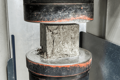
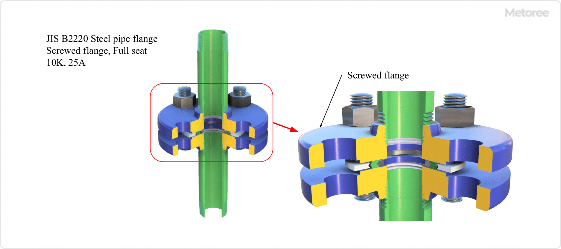
Figure 1. Types of strength tests

A tensile testing service, like bending and compression testing, is a type of strength test for materials.

This test measures the strength of a material when a tensile force is applied to it, i.e., a force that pulls both ends of a test specimen outward. A tensile testing service or universal testing machine is used to apply a tensile load. Measurements are made using load cells, strain gauges, and displacement transducers. By analyzing the relationship between strain and applied load or stress obtained from the test, the mechanical properties of the material can be evaluated.

A tensile testing service is performed in diverse fields. The data obtained from testing contributes to the development of products that can be used safely and reliably.

Uses of Tensile Testing Services

Tensile testing services are used in various fields, such as civil engineering, construction, machinery, and medicine.

The purpose of tensile testing services is for research and development and quality assurance. It is applied to various materials such as metal, rubber, plastic, and paper. Tensile testing is also used in classes at universities and other institutions, where students learn more about materials by actually stretching the material, observing how it is stretched to fracture, analyzing the data, and discussing the results.

The data obtained from tensile testing services are used for various simulations and designs. The data obtained from tensile testing is important for the development of products that can be used safely and reliably, as it supports the foundation of such products.

Principle of Tensile Testing Services

Tensile-Testing-Services_引張り試験-2

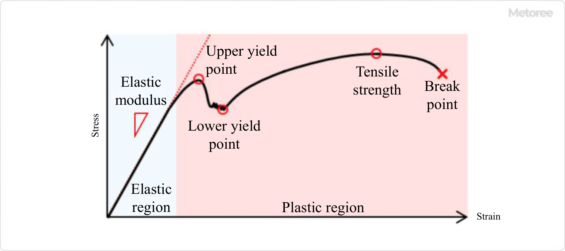
Figure 2. Stress-strain curve

When a tensile force is applied to both ends of a specimen, the material begins to stretch in the direction of the tensile force and eventually breaks.

Stress and strain applied to a material are proportional, but as tensile force is continually applied, the proportional relationship between stress and strain is broken, and the increase in stress in response to changes in strain becomes slower. When the load is further increased and a condition called yield point is passed, the stress drops once but then rises again as the load is applied. The maximum value of stress at this time is the tensile strength.

The tensile testing services are continued until the specimen breaks, which provides reliable data.

Other Information About Tensile Testing Services

1. Data Obtained From Tensile Testing Services

Tensile-Testing-Services_引張り試験-3

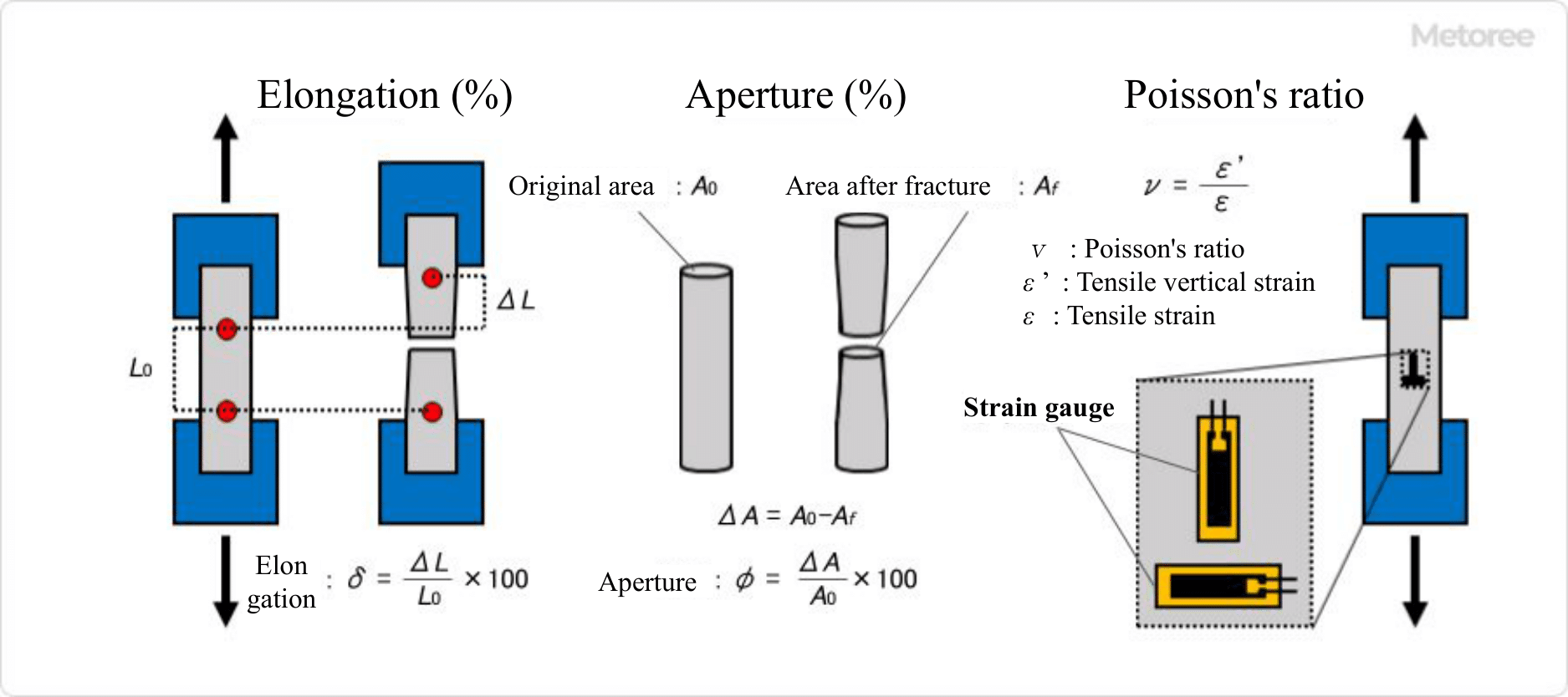
Figure 3. Example of data obtained from a tension test

The information derived from tensile testing services includes stress-strain curves, elongation, elongation-drawing, Poisson’s ratio, etc. By analyzing the stress-strain curves, information, such as elastic modulus, upper yield point, lower yield point, tensile strength, and breaking point, can be obtained.

1. Elongation (%)
Elongation is the ratio of how much a specimen elongates to rupture and is generally smaller for higher-strength specimens and larger for lower-strength specimens. Two marks are placed on the specimen and the distance between the two marks is measured before the test starts and at the time of fracture. Elongation is the change in distance expressed as a percentage of the original distance between the points.

2. Aperture (%)
Aperture is the percentage change in the cross-sectional area of a specimen. The larger this value is, the more suitable the specimen is for deep drawing.  The cross-sectional area of the most distorted portion of the specimen after rupture is measured. The change in the cross-sectional area relative to the original cross-sectional area, expressed as a percentage, is the aperture.

3. Poisson’s ratio
Poisson’s ratio is the absolute value of the ratio of the strain in the direction of the applied tensile load to the strain perpendicular to the applied load. It can be obtained by attaching a biaxial strain gauge to a specimen and performing tensile testing services. The larger the Poisson’s ratio, the more the material strains in the direction perpendicular to the tensile load.

4. Modulus of Elasticity (N/mm2)
The modulus of elasticity is the slope in the elastic range, an interval where the relationship between stress and strain can be expressed as a linear equation. Here, the elastic range is the interval where the material returns to its original shape when the load is removed, even if it is deformed. The slower this slope is, the softer the material is.

5. Upper Yield Point (N/mm2)
The upper yield point is the point where the stress value is highest at the boundary between the elastic and plastic regions and is generally called the yield point. Here, the plastic zone is the section where deformation does not return even if the load is removed. The phenomenon where plastic deformation begins to occur suddenly is called yielding. A high yield point means that the material is less susceptible to plastic deformation.

6. Lower Yield Point (N/mm2)
The lower the yield point is, the lower the stress value on the yield shelf, and the better the forming ability of plastic. The lower this value is, the better the plastic-forming capability. The yield shelf is the section that appears after yielding begins abruptly at the upper yield point, where the stress level decreases and the stress does not increase even if the strain increases.

7. Tensile Strength (N/mm2)
Tensile strength is the maximum tensile stress applied during tensile testing services and is the maximum strength a material can have. The higher the tensile strength, the higher the strength overall.

8. Breaking Point
The breaking point is the point on the stress-strain curve when the specimen breaks. The stress at that point is called the breaking stress, and the strain is called the breaking strain. 

2. Equipment Required for Tensile Testing Services

In tensile testing services, tensile testing machines and universal testing machines are used to apply tensile load, and load cells, strain gauges, and displacement transducers are used for measurement.

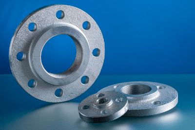
There are various types of testing machines, including motorized, hydraulic, and electromagnetic types. Universal testing machines can perform a variety of tests by replacing jigs. For tensile testing services, jigs such as screw-type flat grips, pneumatic flat grips, and fixed-point rust-type grips are used.

Strain gauges are attached to a test specimen and used to calculate strain by measuring the amount of change in current as the specimen is strained along with the object being measured. Displacement gauges used for measurement are either contact or non-contact, the former being able to measure small elongations with high precision, and the latter minimizing the effect of contact on the specimen. Both of these, moreover, are available in several types, which are used differently depending on the material and application.

カテゴリー
category_usa

Visual Inspection Service

What Is a Visual Inspection Service?

Visual Inspection Services

A visual inspection service is an inspection in which the appearance of a product is checked by the human eye and divided into good and defective products.

A visual inspection service is performed for items that are difficult for machines to detect automatically, such as defects in shape, color differences, uneven paintwork, printing errors, surface scratches, and adherence to any foreign matter.

Since it is difficult to quantify the conditions for judging a product as good in visual inspection service, some inspections are conducted by comparing the product with a limited sample for judgment in order to prevent variations in inspection results among inspectors. In addition to visual inspection by the naked eye, inspection using a magnifying glass, microscope, or image processing system is also classified as a visual inspection service.

カテゴリー
category_usa

Salt Fog or Salt Spray Testing Service

What Is a Salt Fog or Salt Spray Testing Service?

A salt fog or salt spray testing service evaluates the corrosion resistance of metal materials or parts with plated or painted coatings by subjecting them to accelerated corrosion in a salt-rich atmosphere.

Functions that should be maintained over a long period of time, even years, in a natural environment are evaluated on a time basis. In coastal areas, sea salt particles are blown in by sea breezes, and in snowy areas, calcium chloride sprinkled on roads to prevent them from freezing can easily cause rusting. A salt fog or salt spray testing service is conducted to confirm the corrosion resistance of products under such conditions so that they will not be rendered unusable due to rust.

The salt fog or salt spray testing service is regulated by the ISO (International Organization for Standardization). Standards of overseas countries, and standards of automobile manufacturers, specify the test method, testing equipment, and criteria for judgment. A salt fog or salt spray testing service is also sometimes called SST (salt spray test).

Uses of Salt Fog or Salt Spray Testing Services

Salt fog or salt spray testing services are used to evaluate the durability of metal materials against corrosion in a natural environment. The purpose is to verify the quality of metal products that are used outdoors for long periods of time with respect to the occurrence of rust.

Specifically, the test is used to evaluate the corrosion resistance of plating and coating applied to automobiles, construction materials, and their parts. In the case of automotive parts, especially screws used in parts that are loosened or tightened for maintenance and oil pans made of steel plates, high corrosion resistance is required. Salt fog or salt spray testing services are used to evaluate the durability of not only products but also plating and paint against corrosion.

Principle of Salt Fog or Salt Spray Testing Services

Salt fog or salt spray testing services are performed using a special salt fog or salt spray testing machine. The salt fog or salt spray testing services continuously spray a salt-containing solution in a predetermined amount while maintaining a constant temperature to keep the inside of the test chamber in an environment conducive to corrosion.

Test specimens and parts to be tested are left in the test chamber, and the progress of corrosion is observed. After a predetermined time from the start of the test, the test object is removed and the corrosion resistance of the test object is confirmed by measuring the mass loss due to corrosion and visually confirming physical destruction.

Salt fog or salt spray testing services are conducted in accordance with industrial standards such as ISO. The typical test standard is as follows:

  • ISO 9227:2017: corrosion tests in artificial atmospheres – salt spray tests

Other Information on Salt Fog or Salt Spray Testing Services

1. Equivalent Time for Salt Fog or Salt Spray Testing Services

Salt fog or salt spray testing services are used to verify the quality of plating, coating, and industrial products to prevent rust formation in the daily environment where they are used as products. It is one of the accelerated tests to evaluate corrosion resistance in terms of time, which is required in terms of years. However, various industrial standards do not specify the correlation between the natural environment and the test environment.

Each product manufacturer has its own standard for the correlation of how much elapsed time in salt fog or salt spray testing services corresponds to that in the natural environment. Test methods and conditions are in accordance with various industrial standards, and the evaluation time under the specified conditions is determined by each company or industry.

2. Tests Other Than Salt Fog or Salt Spray Testing Services

Salt fog or salt spray testing services can reproduce the “salt environment” and “temperature and humidity changes in a salt-water environment” when the product is used. This is useful for confirming corrosion that may occur in actual use and for reproducing the failure of parts.

There are also several tests that are similar to salt fog or salt spray testing services. For example, the salt-water combined cycle test is a combination of the salt fog or salt spray testing services and the cath test, in which a solution of copper chloride added to salt water is sprayed instead of salt water. Depending on the event to be confirmed and the material to be tested, several combinations of testing methods are available.

カテゴリー
category_usa

Compression Tester

What Is a Compression Tester?

Compression Testers

A compression tester is a type of strength test for materials.

Also called a compression test, a compression tester applies a load to a specimen from above to determine its resistance to compressive forces.

In a compression tester, a load is applied to the specimen from above at a constant rate until the specimen fails or the load reaches a specified value, and the force and displacement applied to the specimen are measured.

This value is converted into a stress-strain diagram, and the maximum compressive stress obtained from the diagram is the compression strength of the specimen. The difference in stress between two specified points on the stress-strain diagram divided by the difference in strain is the compressive modulus. 

カテゴリー
category_usa

Insulation Resistance Test

What Is an Insulation Resistance Test?

An insulation resistance test is a test to confirm the insulation of electrical equipment and circuits. It is performed by measuring the insulation resistance using a measuring instrument called an insulation resistance meter (Megger).

To prevent accidents caused by electricity, such as electric shock and electrical leakage, electrical equipment and wiring are insulated by covering conductors through which electricity flows with cables that do not conduct electricity well to prevent accidents from occurring by intentionally obstructing the flow of electric current.

Insulation resistance testing is an important test to confirm that the resistance has not decreased over time.

カテゴリー
category_usa

Scanning Electron Microscope (SEM)

What Is a Scanning Electron Microscope (SEM)?

Scanning Electron Microscopes (SEM)

A SEM (scanning electron microscope) is a type of electron microscope that allows us to observe the surface conditions of a sample by irradiating the sample with electron beams and detecting the secondary electrons emitted from the sample.

A SEM makes it possible to observe even minute structures that are difficult to observe with an optical microscope. For this reason, it is used in a wide range of fields, such as materials engineering and biochemistry.

Uses of SEMs

_Scanning-Electron-Microscopes-SEM_走査型電子顕微鏡-1

Figure 1. Types and resolutions of microscopes

The magnification of SEMs can be increased to several hundred thousand times, and the resolution can be increased to several nm. It also has features such as a deep depth of focus that make it easy to observe unevenness in the sample.

The magnification limit of an optical microscope is about 1,000x and the resolution limit is about 150nm.

In addition, unlike images obtained with optical microscopes, SEMs provide three-dimensional images with contrast, in which the plane perpendicular to the direction of incidence of the electron beam is darker and the closer the plane is to parallel, the brighter the image becomes.

Taking advantage of these features, SEMs are used to observe the surface conditions of various materials, such as semiconductor and ceramic materials, microorganisms such as bacteria and viruses, and biological samples such as cells. On the other hand, transmission electron microscopes are generally used to observe the internal structure of samples.

Principle of SEMs

Scanning-Electron-Microscopes-SEM_走査型電子顕微鏡-2

Figure 2. Structure and measurement image of scanning electron microscope

In SEMs, an accelerated electron beam is focused on the surface of a sample and irradiated, and the secondary electrons (SE) and backscattered electrons (BSE) generated during the irradiation are detected and analyzed.

By increasing the acceleration voltage and irradiating electron energy, the resolution can be increased to a few nm. Increasing the acceleration voltage increases the resolution. However, too high an acceleration voltage can cause problems such as the influence of reflected electrons from deeper positions in the sample and charging. Therefore, acceleration voltages of several kV to several tens of kV are usually used.

Secondary electrons are electrons ejected from near the surface of the sample when an electron beam is applied.

The state of the electrons differs according to the unevenness of the sample, creating contrast in the image data obtained by measuring secondary electrons and allowing observation of surface irregularities and particle shapes.

Backscattered electrons, on the other hand, are electrons that are bounced back when an electron beam interacts with an atom.

The reflectance of the emitted electrons differs depending on the atom. By measuring backscattered electrons, the contrast is enhanced for each type of atom and the distribution of atoms in the sample can be observed.

Structure of SEMs

SEMs mainly consist of an electron gun that emits electron beams, an electron lens that focuses the electron beams onto the sample surface, and a detector that detects secondary electrons and backscattered electrons.

There are three types of electron guns: thermal electron emission, field emission, and Schottky type, each with different characteristics. Electron lenses are generally of the type in which an electric current is passed through a coil and the electron beam is controlled by a magnetic field, and there are various types, such as the out-lens type and in-lens type.

The inside of SEMs are kept in a high vacuum of about 10^-4 Pa during measurement. In recent times, however, some SEMs have been developed that can measure under low vacuum (about 10^2 Pa) or atmospheric pressure, and are often used in the biological field where samples with high moisture content are used.

Other Information on SEMs

1. Sample Preparation for SEMs

SEMs can be used to measure a wide variety of samples, but some samples require appropriate sample preparation and measurement conditions.

Insulating Specimens
When using an insulating sample, the surface of the sample may be charged by the irradiated electron beam. This can cause image distortion and anomalous contrast, which may result in inaccurate image data. To prevent charging, it is necessary to take measures such as coating the sample surface with a thin sputtering of metal, observing at a low acceleration voltage, and observing under low vacuum conditions.

Samples That Evaporate or Sublimate under High Vacuum Conditions
If evaporation or sublimation occurs under high vacuum conditions, it not only changes the structure or shape of the sample but may also lead to equipment failure. To prevent these problems, it is effective to take measures, such as measuring under low vacuum conditions. In addition, biological samples that contain a lot of water often require separate pretreatment even for observation in a low vacuum.

Magnetic Samples
When using magnetic samples, if the distance between the electron lens and the sample is too close, the sample may become magnetized, making it difficult to adjust the electron beam, and large samples may come off the sample stand and be absorbed by the lens. To prevent these problems, it is necessary to use SEMs with an out-lens system or similar, and fix the specimen with screws or adhesives.

To Observe the Inside of a Sample
If you want to observe the inside of a sample without using the transmission mode described below, you need to process the sample using a focused ion beam (FIB) or the like and observe the cross-section.

2. Major Analytical Devices Attached to SEMs

Scanning-Electron-Microscopes-SEM_走査型電子顕微鏡-3

Figure 3. Example of electromagnetic waves emitted by electron beam irradiation

When a sample is irradiated with an accelerated electron beam, signals such as transmission electrons, X-rays, cathodoluminescence, and absorbed electrons as well as secondary electrons and backscattered electrons can be obtained. Analyzers may be attached to detect these signals.

Transmitted Electrons
If the thickness of the sample is thin enough or if the material is particulate, a portion of the irradiated electrons will be transmitted through the sample and can be detected as transmitted electrons. Generally, transmission electrons are measured by a transmission electron microscope or a scanning transmission electron microscope (STEM), which are independent measurement devices. Scanning transmission electron microscope (STEM) It is possible to observe internal structures that SEMs are not good at.

X-ray
When an atom is irradiated by an electron beam, X-rays are sometimes emitted in addition to electron beams. Since each atom has its own unique energy, it is possible to identify the type of atoms present on the sample surface by detecting the emitted X-rays.

There are two types of X-ray detectors: energy-dispersive X-ray detectors (EDS) and wavelength-dispersive X-ray detectors (WDS). Each has different characteristics and should be selected according to the purpose.

Cathodoluminescence
Cathodoluminescence is the light emitted when a sample is irradiated by an electron beam. By detecting this light, it is possible to measure the crystal properties of the sample, such as crystal defects, impurities, and carrier concentration.

Various other functions can be added by adding other options. Compared to the case where measurement is performed by an independent measurement device, the SEMs have the advantage that the measurement position can be selected while viewing the SEM’s image, allowing for more detailed measurement.

カテゴリー
category_usa

Polarizing Microscope

What Is a Polarizing Microscope?

Polarizing Microscopes

A polarizing microscope is an optical microscope that selects and observes polarized light.

Optical microscopes used in science experiments observe all light reflected from a material through an eyepiece. Light is a wave in which the electric and magnetic fields oscillate in a direction perpendicular to the direction of travel. Light with a regular direction of oscillation in the electric field is called polarized light. A polarizing microscope observes polarized light that is reflected from a material and vibrates in a specific direction.

Linearly polarized light is shone on a material, and changes in the polarization state can be observed as color or light/darkness. When polarized light is selected and observed with a microscope, it is possible to identify the state and components of a substance.

Uses of Polarizing Microscopes

Polarizing microscopes were originally used to determine the state and composition of minerals. However, they are now also used in the development of polymers and biotechnology. Changes in polarization state reflect molecular orientation and crystal structure, allowing evaluation of the internal structure of polymers. Furthermore, in combination with temperature control equipment, phase transition behavior can be observed.

One of the major discoveries made using polarizing microscopes is liquid crystals. Liquid crystals, which are liquid but have a molecular arrangement similar to that of solids, were first observed with polarizing microscopes, leading to the development of today’s liquid crystal televisions and other products.

In addition, many biological materials have a state and molecular structure equivalent to liquid crystals, and polarizing microscopes will continue to play an active role in the medical and pharmaceutical fields in the future.

Principle of Polarizing Microscopes

Polarizing microscopes use filters to select the polarization of light, producing optical microscope images that reflect the optical properties of the sample.

1. Composition of Polarizing Microscope

An ordinary optical microscope consists of a light source, a sample stage, and an objective lens. Light emitted from the light source strikes a material, which enters the objective lens and can be observed through the eyepiece. The principle of polarizing microscopes is basically the same as that of an optical microscope, except that a polarizer is placed between the light source and the sample, and two polarizing plates called an analyzer (analyzer) are placed between the objective lens and the eyepiece lens.

The light emitted from the light source is natural light, the same as fluorescent light, including all directions. This light is converted to polarized light by transmitting it through the polarizer and shining it on the material to be observed. Polarized light that has changed direction when transmitted through a material passes through an analyzer in a cross-nicol arrangement that is perpendicular to the polarizer and can be observed.

2. Image of Polarizing Microscopes

When a sample with no anisotropic refractive index is observed with polarizing microscopes, the linearly polarized light emitted from the polarizer does not change its polarization state and cannot pass through the analyzer, so the field of view when observed through the eyepiece is dark.

When observing a sample whose refractive index differs according to the direction of polarization (birefringence), if the direction of oscillation of the incident linearly polarized light is aligned with the optical axis of the sample, the polarization state of the incident light does not change and the field of view is dark, as described above. On the other hand, when the oscillation direction of the incident light is different from the optical axis of the sample, the incident light is divided into two polarization components due to the birefringence of the sample, and the composite component is different from the polarization state before the sample transmission. The change in polarization state causes the light to pass through the analyzer, resulting in a bright field of view.

Images from a polarizing microscope appear tinted due to the optical path difference between the two light components caused by the birefringence of the sample. In polarizing microscopes, the stage on which the material is placed can be rotated 360° in order to change the angle of polarized light with respect to the optical axis of the sample.

Other Information on Polarizing Microscopes

Applications of Polarizing Microscopes

Polarizing microscopes use techniques that can be used in combination with other optical measurement methods because they can study crystal domains and even their orientation.

1. Fluorescence Measurement
Polarizing microscopes can be used in combination with fluorescence measurement. Normal fluorescence measurements are ensemble information obtained from various positions and orientations of the crystal domains. However, since the optical properties change depending on the orientation of the crystal domains, polarizing microscopes, which can identify the crystal orientation, come into play. Polarizing microscopes allow us to observe the emission of polarization information in a specific direction by injecting a laser with a specific direction of polarization in the incident light.

2. Time-Resolved Measurement
Polarizing microscopes can also be used in combination with time-resolved spectroscopy. While ordinary time-resolved spectroscopy provides ensemble information from various positions and orientations of crystal domains, polarizing microscopy allows time-resolved spectroscopic measurements of absorption and emission by determining the orientation and position of crystal domains.

カテゴリー
category_usa

Printed Circuit Board (PCB)

What Is Printed Circuit Board (PCB)?

PCB is an abbreviation for “printed circuit board,” which can be found inside PCs and home appliances.

Most PCBs are square or rectangular and are about 1 cm thick. The size varies depending on the product in which it is incorporated, ranging from a size that can be held in both hands to one that can be placed on the top of a finger.

PCBs are the heart of devices and equipment, with conductor wiring and electronic components mounted on an insulator substrate.

The practical use of PCBs began around 1950, and the manufacturing and development of devices and equipment has dramatically increased.

Uses of PCBs

PCBs substrates are used in a wide range of applications, from general electronic devices such as home appliances and PCs to large equipment in the manufacturing industry, automobiles, and railroads.

PCBs are the heart of electronic devices, so performance and reliability depend on them.

In recent years, as AI and IoT devices have become more widespread, their durability and density have increased, and even common consumer electronics products now incorporate high-performance PCBs.

This trend is expected to continue.

Features of PCBs

PCBs are characterized by the formation of circuits on the PCBs, on which integrated circuits, capacitors, transistors, resistors, and other components are installed, and electrical communication between the electronic components is performed.

Exactly as the heart pumps blood to various parts of the body, signals and power are transmitted to operate electronic devices.

Since its commercialization, PCBs have greatly improved the speed, durability, and reliability of electronic devices, and this evolution has continued in recent years.

For example, the material of PCB substrates is linked to their durability.

Phenolic resin is the most common substrate, and although it is less durable and prone to warping, it is used in consumer electronics because it is easy to process and can be mass-produced at low cost.

Because of its flexibility, it can be used as a flexible substrate that can be folded and applied to products.

On the other hand, polyimide and epoxy resin substrates have high strength and heat resistance, so they are incorporated into products that are used in harsher environments than usual, such as large equipment and automobiles.

There are also several types of circuit formation for substrates, the most basic of which are substrates with circuits on only one side, double-sided substrates with circuits on both sides, and multilayered substrates with circuits inside and stacked on top of each other.

The type of board is determined by the electronic components to be mounted and the space available inside the product.

For example, if the product is small but has complex circuits, a multilayer board is selected.

カテゴリー
category_usa

Digital Storage Oscilloscope

What Is a Digital Storage Oscilloscope?

A digital storage oscilloscope is a measuring instrument that converts changes in electrical signals over time into digital data, records them in its internal memory, and presents them on a display.

Unlike testers, which only measure voltage or current at a single point in time, oscilloscopes can observe the period/frequency of an electrical signal, the rising edge of a signal, and the time/phase difference between multiple signals.

Oscilloscopes are broadly classified into digital storage oscilloscopes and analog oscilloscopes. While analog oscilloscopes project electrical signals onto a cathode-ray tube in real-time, digital storage oscilloscopes, which are used here, collect information as “points” obtained by sampling electrical signals at discrete time intervals and display pseudo waveforms.

Uses of Digital Storage Oscilloscopes

Oscilloscopes are measuring instruments used to observe electrical signals, such as voltage and current, in electrical circuits as waveforms with the horizontal axis of time. They are used to verify and debug the operation of industrial and consumer equipment during development, and to analyze the cause of product failure.

Digital storage oscilloscopes convert electrical signals into waveforms after data processing, such as A/D conversion. As a result, they used to have a disadvantage in terms of real-time performance compared to analog oscilloscopes.

However, since 2000, the screen update rate has been improved to a level that does not interfere with practical use. In addition, since the price of digital storage oscilloscopes has gradually decreased, they are primarily used nowadays. 

Principle of Digital Storage Oscilloscopes

1. Input Signal Processing

Digital storage oscilloscopes use an attenuator to adjust the sensitivity of the input signal, an amplifier to optimize the amplitude, and an A/D converter to convert the signal to a digital value. The digital value is recorded in the recording memory as the data of a single point in the waveform.

2. Recording Memory

The recording memory has a FIFO (first-in-first-out) memory structure. When the recording memory is full, the oldest data is discarded and new data is written. As a result, the recording memory is always kept up-to-date with the latest data.

3. Signal Waveform

Writing from the A/D converter to the recording memory is controlled by the trigger circuit. When writing to the recording memory is stopped by a signal from the trigger circuit, the waveform record, which is a collection of data for each point stored there, is transferred to the display memory. Based on the data in the display memory, the signal waveform is displayed on the oscilloscope display.

4. Pre-trigger

When the trigger circuit signal immediately stops the acquisition of a new signal, the waveform record stored in the recording memory is that before the trigger signal. This ability to observe input signals prior to the trigger signal is one of the features of digital storage oscilloscopes and is called a pre-trigger. With analog oscilloscopes, it is difficult to capture waveforms before the trigger signal because the sweep of the bright line starts after the trigger signal is received.

How to Select Digital Storage Oscilloscopes

When selecting a model, it is important to use an oscilloscope with sufficient specifications for the measurement contents. Specifically, the following points should be considered:

  • Frequency response
    The wider the frequency band, the better
  • Sampling frequency
    The faster the sampling frequency, the better
  • Number of channels
    The higher the number of channels, the more advantageous
  • Memory length
    The larger the memory capacity, the greater the advantage
  • Available probe types
    The more probes available, the better
  • Trigger function
    It is advantageous if various trigger conditions can be set.

In addition to the basic use of digital storage oscilloscopes for waveform observation, their applications are expanding to include timing verification, waveform analysis, and compliance testing. On the other hand, the higher the performance required, the higher the price will inevitably be. Therefore, there is an increasing need to select a model with functions that match the intended use.

Other Information on Digital Storage Oscilloscopes

1. Use of Waveform Recording

Since digital storage oscilloscopes record input signals as digital data in the recording memory, waveform analysis using the data in the recording memory, for example, frequency analysis of signals by FFT operations, can also be performed. Furthermore, the data can be output to an external memory device (USB memory, etc.) for analysis and data storage using a PC.

2. Anti-aliasing Measures

Digital storage oscilloscopes may observe incorrect waveforms if the sampling interval is too long compared to the frequency of the input signal. This is called “aliasing.” To prevent this, it is necessary to acquire waveform data at a sampling frequency that is more than twice the maximum frequency of the input signal.

カテゴリー
category_usa

Flange Screw

What Is a Flange Screw?

Flange Screws

A threaded flange is a type of threaded joint used in piping, in which the connection method between the flange and the pipe (pipe) is a threaded type.

A Flange Screwed Flange has a female tapered pipe thread on the inside diameter of the flange, and is connected to a pipe end with a male tapered pipe thread by threading it.

The taper pipe thread is defined in JIS B0203 as “a thread whose main purpose is to ensure tightness of the threaded portion when joining piping, piping components, fluid equipment, etc.”.

Applications of Threaded Flange Screws

Flange-Screws_ねじ込みフランジ-1

Figure 1. Example of screwed flange use

Flange Screws are used for air piping where the fluid pressure and temperature are not very high and leakage of a certain amount of fluid is not dangerous. Unlike other connection methods (welding, loose joint, etc.), the use of threaded flanges is limited.

When a Flange Screw is used and a leak occurs, it is necessary to remove the pipe, rewrap the sealing tape, and retighten it. In many cases, this type of flange is used when the piping and flange must be easy to install and remove.

In addition, the connection method between the piping and the flange is threaded, which can be used when welding or other fireproofing cannot be used on site. In selecting Flange Screws, the material, pressure resistance, size, etc. are selected based on the type of fluid, pressure, temperature, flow rate, etc.

Principle of Flange Screw

Flange-Screws_ねじ込みフランジ-2.

Figure 2. Principle of screwed flange

The principle of a Flange Screw is exactly the same as that of an ordinary piping flange, and the flange surfaces to be connected are sealed by making them adhere to each other.

The screw standards used are as follows

  • JIS B0203 Tapered pipe threads
  • ASME B1.20.1 Pipe Threads, General Purpose, Inch

Flange Screws are used when the pressure and temperature of the fluid to be used are limited so that leaks are not hazardous in the unlikely event that they occur. When screwing in piping, sealing tape or similar material can be wrapped around the male threads of the piping to improve the sealing performance of the installation.

Flange Screws, like normal pipe flanges, require bolts and nuts for flange fastening to be evenly tightened. Uneven tightening may result in leakage. For this reason, it is common practice to tighten bolts and nuts diagonally, rather than in the order of their sequence.

It is also important to tighten the bolts and nuts at the specified torque value for the gasket material and bolt/nut. Tighten the bolts and nuts in diagonal order, gradually increasing the tightening torque until the required tightening torque value is reached. When used with high-temperature fluid, the tightening of the threads may loosen due to thermal expansion after the actual flow of high-temperature fluid, in which case the bolts and nuts need to be retightened.

Types of Threaded Flange Screws

Flange-Screws_ねじ込みフランジ-3

Figure 3. Example of JIS B2220/B2239 screwed flange

1. Classification by Standard

There are various standards for flanges, such as JIS, JPI, ASME/ANSI, etc. Typical examples are as follows.

  • JIS B2220 Steel pipe flanges
  • JIS B2239 cast iron flange
  • JPI-7S-15-2011 Flanges for petroleum industry
  • ASME/ANSI B16.5 Pipe Flange and Flanged Fittings

In “JIS B2220 Steel Pipe Flanges,” nominal pressure ranges from 5K to 63K, but Flange Screws are applied to nominal pressures of 5K, 10K, 16K, and 20K. In “JPI-7S-15-2011 Flanges for the Petroleum Industry” and “ASME/ANSI B16.5 Pipe Flange and Flanged Fittings”, the flanges are applied to nominal pressure classes 150, 300, 600, 900, 1500 and 2500.

The following is an example of JIS standard flange specifications.

  • JIS B 2220 TR FF 10K 80A SCS 13A
  • Steel Pipe Flange, Threaded Flange, Full face, 10K, 80A, SCS 13A

2. Classification by Material

Typical flange materials in JIS standards are as follows

Carbon Steel

  • Rolled material: JIS G3101 SS400, G4051 S20C/S25C
    ASTM A515 70, A516 70 
  • Forging: JIS G3201 SF390A/SF40A, G3202 SFVC1
    ASTM A105, A350 LF2
  • Casting material: JIS G5101 SC410/SC480, G5151 SCPH1
    ASTM A216 WCB

Low Alloy Steel

  • Rolled: ASTM A201 A/B, A387 11 CL2
  • Forging: JIS G3202 SFVC2A, G3203 SFVAF1/SFVAF11A
    ASTM A182 F1/F11 CL2/F12 CL2
  • Casting material:JIS G5151 SCPH2/SCPH11/SCPH21
    ASTM A217 WC1/WC6, A352 LC1

Stainless Steel

  • Rolled materials:JIS G4304/4305 SUS304/SUS304L/SUS316/SUS316L
    ASTM A240 304/304H/304L/316/316H/316L/317
  • Forging: JIS G3214 SUSF304/SUSF304L/SUSF316/SUSF316L
    ASTM A182 304/304H/304L/316/316H/316L
  • Casting materials:JIS G5121 SCS13A/SCS14A/SCS16A/SCS19A
    ASTM A351 CF3/CF3M/CF8/CF8M/CG8M

Flanges are used in pairs, and both flanges must be made of the same material. The selection of flange material is indicated in each standard; in the JIS standard, “nominal pressure” and “material group number” are selected according to the “maximum working pressure” and “fluid temperature” of the working fluid flowing in the pipe.

It is important to select materials from several standard materials classified by material group number according to the flange manufacturing method, operating environment, cost, and other factors.