カテゴリー
category_usa

Electrical Discharge Machining (EDM)

What Is Electrical Discharge Machining (EDM)?

Electrical Discharge Machining (EDM)

EDM is a machining method in which the surface of the workpiece is removed by heat emitted from the electrode material.

The workpiece is fixed to the bed of the processing machine, and under an environment of water, oil, or a water-oil mixture. An electric current is applied between the workpiece and the electrode material (shape electrode or wire electrode) to remove the workpiece surface using the heat emitted from the electrode material.

In general, machining speed is lower than that of cutting, but the desired shape can be faithfully reproduced. However, the material to be processed must be able to conduct electricity. It is not suitable for processing plastic, wood, ceramics, or materials with insulation coatings.

Uses of EDM

1. Engraving EDM Processing

This process is used for various types of dies and molds. Shape electrodes are used to process fine patterns that are difficult to express by cutting or when the cutter radius cannot be removed by cutting.

Most plastic, die-cast, and forged products are made using this process. This method is used especially when a regular surface shape is required, or when a very fine radius is required at the corners. It is also used when the workpiece is very hard or brittle and cannot be machined by cutting.

2. Wire EDM Processing

High-precision processing is possible for the metal material to be processed. Generally, this is a two-dimensional process, but tapered processing is also possible. The unique feature of this method is that it can process any workpiece, but it is necessary to select the processing conditions and liquid for each workpiece. Liquid refers to water, oil, or a mixture of oil and water.

3. EDM for Small Holes

Fine-hole EDM is capable of machining small holes with diameters from 0.3 mm to 3 mm in the metal material to be processed. The principle is the same as that of a square EDM machine, but the electrode is a thin wire, and depending on the length of the hole to be drilled, it may take longer. When drilling small holes with cutting, the holes may be drilled at an angle due to the drill characteristics. Small hole EDM can drill holes vertically compared to cutting.
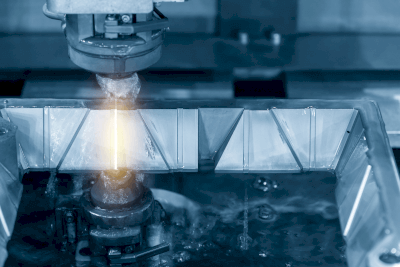
Principle of EDM

When voltage of 100 volts is applied between the EDM electrode and the workpiece and the distance between the electrode and the workpiece is reduced to a few tens of microns. An electrical discharge phenomenon occurs between the electrode and the workpiece, and sparks are generated. To prevent the sparks from igniting other materials, processing is performed in an environment with water, oil, or water oil. The heat radiation (6,000°C or higher) generated by the sparks melts the surface of the workpiece and removes the surface. The desired shape is created by using the electrical discharge phenomenon generated by the use of an electric circuit (pulse circuit).

Types of EDM

1. Engraving EDM Processing

The electrode material is mainly a conductive metal such as copper, graphite, or tungsten. EDM is applied between the workpiece and the electrode at a rate of over 1,000 times per second to melt the surface of the workpiece into the desired shape.

2. Wire EDM Processing

The electrode material is an ultra-fine metal wire (zinc, brass, etc., 0.05 mm or more in diameter), and EDM is applied between the workpiece and the electrode. Two-dimensional processing is performed while the metal wire melts the workpiece in minute amounts. The electrode does not touch the workpiece, but removes the shape in the processing fluid (water, oil, or water-oil mixture).

One of the characteristics of wire EDM is that it is possible to create a surface with a good surface roughness by repeatedly oscillating the electrode (known as low-run machining). This machining method is suitable for precision machining because it produces a machined surface with lower surface roughness than cutting.

3. Small-Hole EDM

A rod electrode (copper, brass, tungsten, etc.) is used as the electrode material. A fine hole can be processed by placing the electrode close to the workpiece to generate EDM and remove the metal.

Other Information on EDM

1. Problems With EDM

Although EDM is capable of fine processing, there are some problems.

EDM cannot process a workpiece that does not conduct electricity. Also, the amount of workpiece removal is small, so the process takes a long time and is not suitable as a mass-production processing method.

The electrodes used in EDM wear not only the workpiece but also the electrodes. It is necessary to prepare a spare electrode and replace it as necessary. Especially in die-sinking EDM, it is necessary to make shaped electrodes, and it is necessary to estimate the labour hours required to make electrodes.

2. Equipment Required for EDM

EDM machines are required for each processing method (engraving EDM, wire EDM, and small-hole EDM), and most machines are NC-equipped and controlled by NC programs. Recent technological innovations have allowed some machines to be equipped with complex moving robot arms, which have the advantage of automating the transfer of the workpiece and electrode.

カテゴリー
category_usa

Welding Service

What Is a Welding Service?

Welding Services

A welding service is the process of joining two or more metal parts by applying pressure, heat, or both.

In general, metals begin to melt when they are subjected to external energy, such as pressure or heat. A welding service is a process in which metals are joined by this external energy and then cooled and adhered to each other.

Uses of Welding Services

Welding services are used to join metals of the same type or different metals. Specific applications are as follows:

  • Automobile parts and machinery frames
  • Workbenches
  • Aircraft parts
  • Ship bodies
  • Electrical equipment
  • Construction equipment
  • Various bogies
  • Rolling stock and car bodies
  • Plant piping and boilers

As you can see, they are used in every field of industry. Other examples include metal furniture, office automation equipment, housing equipment, sports equipment, theater equipment, and park playground equipment.

Principles of Welding Services

Welding services can be broadly classified into three types: fusion welding, which joins in a molten state; pressure welding, which joins in a solid state; and brazing, which welds in a molten-solid state. The appropriate welding method is selected according to the intended use after joining.

1. Fusion Welding 

Fusion welding is a method in which a portion of the metal to be joined is melted by heat, light energy, etc., and then cooled and solidified. Fusion welding includes arc welding, plasma welding, and laser welding. The feature of this method is that it is possible to process thicker plates and larger sizes. However, it has the disadvantage of production variation due to the tendency for distortion to occur in the joint.

2. Pressure Welding 

In pressure welding, the joint is heated and melted by friction or gas combustion heat, and then mechanical force is applied to the joint. Pressure welding includes gas pressure welding, friction welding, resistance welding, diffusion welding, ultrasonic pressure welding, and explosion welding. The characteristics of pressure welding are that it can weld thin sheets of metal and production conditions can be easily controlled. However, it is not suitable for parts that require high joint strength.

3. Brazing

Brazing is a method of joining metals by heating a solder called “brazing filler,” which has a lower melting point than the metal to be joined, and allows it to penetrate between the surfaces to be joined. There are two types of brazing materials: hard brazing filler metal with a melting point of 450°C or higher and soft brazing filler metal with a melting point of less than 450°C. Soft brazing filler metal is used for electronic components.

Soft brazing is especially used in joining electronic components and connectors and is called soldering. It is characterized by its ability to join dissimilar metals and its advantage of not causing damage to the metal being joined since it does not melt the metal. However, it is not suitable for joining thicker metals because its strength cannot be maintained.

Types of Welding Services

Of the many welding methods, there are four typical welding services that are often used: arc welding, spot welding, laser welding, and brazing.

1. Arc Welding

Arc welding is the most commonly used method of fusion welding. When electrodes are placed at two points in the air and a high voltage is applied between them, at a certain voltage, the insulation of the air is broken and an electric current flows. At that time, a sharp light that draws an arc and high heat is generated at the same time. This method of welding utilizes this heat source. Arc welding can be further classified into several types.

Covered Arc Welding
Covered arc welding uses a welding rod made of the same material as the material to be welded as an electrode to generate an arc. The welding rod is coated with flux. Since this is mainly a manual welding process, it has the disadvantage that the skill of the welder tends to vary.

Semi-automatic Arc Welding
This is called semi-automatic arc welding because welding wire is supplied automatically and welding is done manually. Once the welder becomes accustomed to the welding process, it is relatively easy to weld. Semi-automatic welding uses an inert gas called shielding gas to protect the weld from oxygen in the air. Since the shielding gas is carried away by the wind, it is not suitable for outdoor welding.

There are flux wires that do not require shielding gas and can be welded outdoors. The center of the wire is filled with flux.

TIG  Welding
TIG welding is welding using Tungsten inert gas. Tungsten, which does not wear out, is used for the discharge electrode, and argon gas or helium gas is used for the shielding gas.

There is no scattering of sparks, the arc is stable, and almost no spatter is produced. In addition to TIG welding, other types of arc welding using shielding gas include MIG (metal inert gas) welding and MAG (Metal Active Gas) welding.

MIG welding uses a consumable electrode for the discharge electrode. MAG welding is a type of arc welding that uses active gas (carbon dioxide or a mixture of argon and carbon dioxide) as the shielding gas and is also called carbon dioxide gas arc welding. It is not suitable for non-ferrous metals such as aluminum.

2. Resistance Spot Welding

Resistance spot welding is a method of welding by passing an electric current across the weld area and using joule heat due to electrical resistance. It is used for joining lids of lithium-ion batteries.

3. Laser Welding

Laser welding is a welding method that uses a high-energy-density laser beam as a heat source. It is faster than other welding methods and produces less distortion. There are two types of lasers used for laser welding: gaseous and solid-state lasers. Gaseous lasers use a gas, such as carbon dioxide, to extract light. Solid-state lasers include YAG lasers, fiber lasers, and semiconductor lasers.

4. Brazing

Brazing is suitable for the precision joining of electronic components and thin sheets because it does not damage the original metal. Therefore, it can be used to join dissimilar metals and simultaneously join a wide variety of electronic components and is also suitable for automated production.

カテゴリー
category_usa

Non-Destructive Testing (NDT) Service

What Is a Non-Destructive Testing (NDT) Service?

Non-destructive testing (NDT) services are tests to determine the presence, size, shape, distribution, etc., of scratches on a surface or interior surface without destroying the object being tested.

Destructive testing is a testing method in which pressure, temperature, vibration, etc., are applied to an object until it is destroyed, and the permissible limit of defect generation is directly examined. NDT service is an indirect testing method and has the disadvantage of not being able to reliably determine the conditions under which defects can occur. It can detect defects without damaging the shape or function of the object. This makes it possible to test buildings, plants, railways, aircraft, etc., while they are in operation.

Uses of NDT Services

NDT services are used in a wide variety of fields.

Depending on the type of NDT Services, the purpose of use and the materials that can be used will vary. For example, eddy current testing can detect flaws on the surface of conductors without contact and at high speed. However, it cannot be used on non-conductive materials and can only detect internal flaws to a limited extent. Therefore, it is necessary to select the appropriate test for the intended use.

Principles of NDT Services

Various NDT services exist, each with different principles. The following is a description of the principles of typical NDT Services:

1. Radiation Transmission Testing

Non-Destructive-Testing-NDT-Services_非破壊試験-1

Figure 1. Principle of radiation transmission testing

In a radiation transmission test, an object is exposed to X-rays or γ-rays, and the images projected on a film or image plate are used to determine the internal state of the object.

Radiation has the property of penetrating through materials, but the ease of penetration depends on the condition of the object’s interior. For example, a damaged part of an object is generally more easily penetrated by radiation than a healthy part, resulting in a darker appearance on the film. The shading of the film is caused by the reaction of the emulsion that makes up the film to radiation.

Radiation transmission tests are classified into several methods, depending on the method of photography and other factors. For example, image data is obtained by using an image plate instead of a film.

2. Ultrasonic Testing

Non-Destructive-Testing-NDT-Services_非破壊試験-2.

Figure 2. Principle of ultrasonic testing

Ultrasonic flaw testing is a test used to estimate the internal condition and thickness of an object by applying ultrasonic waves to the object.

Ultrasonic testing can be broadly classified into three methods: transmission, pulse reflection, and resonance. The methods are further classified according to the type of ultrasonic wave and the method of application. They are used in different ways depending on the intended use.

Transmission method
The transmission method estimates internal conditions by comparing the strength of transmitted and received ultrasonic waves.

A probe is positioned on the surface of the object to introduce ultrasonic waves, and another probe is placed at the bottom of the object to receive these waves. The ultrasonic waves, initiated by the surface probe, penetrate the interior of the object and reach the probe at the bottom. If there is a flaw within the object, the ultrasonic wave is unable to pass beyond it, resulting in a weakening of the wave. This attenuation of ultrasonic waves reveals internal defects through the formation of ultrasonic shadows.

Pulse Reflectometry
The pulse reflection method uses the reflection of ultrasonic waves to identify the presence, location, size, etc. of a flaw.

A probe capable of transmitting and receiving ultrasonic waves is placed on the surface of the object. Ultrasonic waves incident inside the object from the probe reflect off the bottom surface and return to the probe. Ultrasonic waves are also reflected if there are scratches or other defects inside the object. The internal condition of the object is estimated by receiving the transmitted pulse, the reflected wave from the scratch, etc., and the reflected wave from the bottom surface.

Resonance Method
The resonance method is a method to measure the thickness of an object by utilizing the resonance of the object.

When ultrasonic waves are injected into an object while continuously changing the wavelength, the object resonates when an integer multiple of half wavelength equals the thickness of the object. The vibration energy for resonance is supplied by the oscillator, and the occurrence of resonance can be confirmed by detecting the increase in current. The thickness of the object is estimated from the sound velocity, frequency, and resonance order at resonance. It is also possible to estimate the presence or absence of scratches inside the object from the strength of the resonance.

3. Magnetic Powder Flaw Testing

Non-Destructive-Testing-NDT-Services_非破壊試験-3

Figure 3. Principle of magnetic particle inspection testing

The magnetic particle flaw test is a test used to visually check for flaws near the surface of an object using a leaking magnetic field.

As the magnetic flux flows through the ferromagnetic object and increases, a portion of the flux leaks into the external space in the area where the flaw is located. When the magnetic powder is sprinkled in this leaking magnetic field, the magnetic powder adheres to the area around the flaw and a magnetic powder indication pattern appears. By observing this pattern, even minute scratches can be detected.

Magnetic powder testing is directional in detecting flaws and is classified as a method to magnetize the flaw detection point in the appropriate direction. It can also be classified into several methods, depending on the magnetic powder used and the light source for observation. These methods should be used appropriately depending on the shape of the object and the flaw to be detected.

4. Penetration Flaw Detection Test

Non-Destructive-Testing-NDT-Services_非破壊試験-4

Figure 4. Principle of penetrant testing

Penetration testing is a test used to detect flaws on the surface of an object using a penetrant.

First, the surface of the object is cleaned as a pretreatment, and the inside of the flaw is opened and dried. Next, the penetrant is applied to the surface of the object, and the excess penetrant is removed. Finally, a developing film is applied to absorb the penetrant that has penetrated into the flaw, and the enlarged penetrant indication pattern is observed.

There are two types of observation methods, three types of penetration fluid removal methods, and four types of development methods in the penetration test, and the appropriate combination is selected according to the application.

5. Eddy Current Testing

Non-Destructive-Testing-NDT-Services_非破壊試験-5

Figure 5. Principle of eddy current testing

The eddy current test induces eddy currents on the surface of a conductive object and detects the turbulence of the eddy currents to determine whether a flaw exists.

When a coil with alternating current is brought close to the object, eddy currents are generated near the surface of the object due to electromagnetic induction. If the surface of the object is scratched, the eddy currents are disturbed. The disturbance of the eddy currents causes a change in the magnetic flux inside the coil, resulting in a change in the electromotive force of the coil, and by detecting this change in electromotive force, the disturbance of the eddy currents, in other words, the presence or absence of a scratch, can be confirmed.

Since eddy currents are induced intensively only near the surface of an object and hardly ever inside the object, eddy currents are mainly used for flaw detection on the object’s surface. The phenomenon in which eddy currents decay rapidly inside an object is called the skin effect. However, the depth of the flaw can sometimes be estimated by using the properties of the eddy current phase.

カテゴリー
category_usa

Static Electricity Testing Service

What Is a Static Electricity Testing Service?

Static Electricity Testing Services

A static electricity testing service is also called ESD (electro-static discharge) testing.

Static electricity testing service confirms and evaluates that no damage or malfunction will occur even when high voltage caused by static electricity is applied to electronic components and semiconductors, which are the test objects.

Static electricity testing service can be conducted using different static electricity generation models: the human body model (HBM), which assumes that static electricity is discharged from the human body. The machine model (MM) assumes the case where static electricity is discharged from a machine, and the charged device model (CDM) assumes the case where the device itself, such as a component or semiconductor, is electrically charged.

カテゴリー
category_usa

X-ray Inspection System

What Is an X-ray Inspection System?

An X-ray Inspection System is a device that irradiates an object with X-rays and measures and analyzes the X-rays transmitted through the object to detect foreign matter or damage inside the object without destroying it.

It is also possible to identify elements and accurately measure the content rate of hazardous substances.

Uses of X-Ray Inspection System

X-ray Inspection Systems are used not only in the medical field and in the manufacturing and processing of food and electronic components, but also in the construction and aviation industries. Typical applications are as follows

  • Medical field: Radiography, CT scans, etc.
  • Manufacturing industry: detection of foreign objects, product inspection, etc.
  • Construction industry: non-destructive testing of concrete, etc.
  • Aviation industry: baggage inspection at airports, etc.X-ray-Inspection-System_X線検査装置-3

In the medical field, X-ray Inspection Systems produce white contrast in areas where the intensity of transmitted X-rays is high, and black contrast in areas where the irradiated X-rays are attenuated. The intensity of transmitted X-rays is determined by factors such as the atomic number, density, and thickness of the material. The higher the atomic number, the higher the density, and the thicker the material, the more the irradiated X-rays are shielded and the intensity of transmitted X-rays decreases.

For example, in the case of radiography of the human body, the contrast is as follows

  • Highly transparent (black): air (lungs, digestive tract gases) and fat
  • Medium (gray): water (pleural fluid, ascites, urine), soft tissue (brain, abdominal organs, muscles, etc.)
  • Low permeability (white): bone, calcification (gallstones, kidney stones, etc.), metal (artificial joints, etc.)

Using this fact, technology has been developed to convert CT images into 3-dimensional color images.

Principle of X-Ray Inspection Systems_X-ray-Inspection-System_X線検査装置-1

X-rays are electromagnetic waves with wavelengths of about 10-3 nm – 10 nm, and are a type of radiation. There are several types of radiation, including α-rays, β-rays, γ-rays, X-rays, and neutron rays, etc. Unlike particle rays such as α-rays, X-rays are electromagnetic waves with a short wavelength and can penetrate most materials.

When X-rays are irradiated to a material, some of the X-rays collide with electrons in the material and interact with them, causing absorption and scattering phenomena. Among the irradiated X-rays, the X-rays that do not cause these phenomena are the transmitted X-rays that penetrate the material.

Structure of X-Ray Inspection SystemX-ray-Inspection-System_X線検査装置-2

The X-ray Inspection System consists of an X-ray irradiation system and an X-ray photosensitive section. The X-ray photosensitive section is placed between the irradiated object and a film is used to contrast the intensity distribution of the transmitted X-rays. The conventional X-ray photosensitive section consists of a photosensitive film clipped with fluorescent sensitized paper and placed in a case called a cassette. Today, most X-ray Inspection Systems are digital, using Imaging Plates (IP) or Flat Panel Detectors (FPD) instead of photosensitive film.

Types of X-Ray Inspection Systems

X-ray Inspection Systems can be divided into the following main types, which have evolved over time

1. X-Ray TV Systems

X-ray TV systems capture the internal conditions of the body in real time as moving images and allow observation on a TV image. Contrast agent is injected into organs and blood vessels, and the images can be taken while checking how the contrast is formed. It is also possible to observe and treat patients using an endoscope or other equipment while fluoroscopically observing them with an X-ray TV system.

2. CT Baggage Inspection

The common method of baggage inspection at airports is to irradiate X-rays vertically and observe the inside of the baggage. This system is expected to alleviate congestion at baggage checkpoints at airports, since baggage can be inspected without opening the baggage. The system has been introduced at some airports in Japan and abroad.

3. Miniaturization of X-Ray Inspection System

With the development of portable X-ray sources and the digitization of photosensitive areas, a variety of portable X-ray Inspection Systems have been developed and marketed today. They are mainly used as nondestructive inspection equipment at factories and construction sites. They can check for internal cracks, fissures, corrosion, and other abnormalities without destroying the inspection target. X-ray Inspection Systems are often used for completion and periodic inspections at factories and construction sites, and their applications are expanding due to their miniaturization, such as underwater inspections and attachment to self-propelled robots.

Other Information on X-ray Inspection Systems

Qualifications for X-Ray Inspection System

In order to use X-ray Inspection System, a person who has obtained the “X-ray Operation Chief License” must be appointed as the responsible person. The holder of this license is responsible for X-ray-related maintenance work, and his/her duties include checking the restricted areas to prevent radiation hazards, X-ray Inspection System inspection, and X-ray irradiation adjustment and management.

To obtain the certification, the candidate must take the following four subject tests and pass with a total score of 60% (40% in each subject) or higher.

  1. Knowledge of X-ray management
  2. Knowledge of X-ray measurement
  3. Effects of X-rays on the human body
  4. Relevant laws and regulations

This license is not renewable and can be held permanently once passed.

カテゴリー
category_usa

Weathering Tester

What Is a Weathering Tester?

A weathering tester is a test to examine the resistance of a product to degradation caused by natural environmental factors such as sunlight and rainfall.

Another type of weathering tester is the “outdoor exposure test,” in which materials are actually exposed to the outdoors for a year or so to see how they fare in a long-term test.

カテゴリー
category_usa

Insulation Resistance Tester

What Is an Insulation Resistance Tester?

An insulation resistance tester is a device used to diagnose insulation conditions. Insulation resistance testers that can apply a high voltage of about 1,000 VDC according to the voltage of the power system are also available.

It is very important for equipment that uses electricity to be insulated. If the insulation condition deteriorates, it can cause electrical leakage, fire, or electric shock. To prevent the above accidents from occurring, it is necessary to periodically evaluate insulation performance with an insulation resistance tester.

Uses of Insulation Resistance Testers

Insulation resistance testers are used to quantify insulation capability. It is rarely seen in ordinary households.

In production, they are used for final testing of electrical products at the factory where they are shipped. In addition, maintenance personnel of electrical equipment often have it as a measuring instrument for maintenance.

Resistance measurement involves the application of a voltage, and the applied voltage varies according to the system voltage. For example, insulation resistance testers that apply a voltage of 25 to 50 V are used to measure the insulation of telephone lines, while 125 VDC is used for home appliances. A voltage of 1,000 VDC is applied to high-voltage distribution lines and power plants.

Principle of Insulation Resistance Testers

An insulation resistance tester consists of a wiring terminal, a switch, a DC power supply, an ammeter, and a current protection element.

The wiring terminal uses two terminals, called the ground terminal and the line terminal. The ground terminal is grounded, and the line terminal is connected to the measuring section for measurement.

By pressing the switch, a DC voltage created by a DC power supply is applied. The minute current flowing to the ground is called leakage current, and insulation resistance tester is obtained by measuring the leakage current when the voltage is applied with an ammeter.

Since a high-voltage voltage is applied, the impedance is increased with a current protection element to prevent overcurrents from flowing in the circuit. Due to the current protection element, the internal impedance of the insulation resistance tester is designed to be very high.

The higher the insulation resistance value, the better the insulation performance. If an insulation breakdown occurs, the insulation resistance will be extremely low.

Other Information on Insulation Resistance Testers

1. Purpose of Using an Insulation Resistance Tester

Insulation resistance testers are used to measure the insulation condition of electric lines and electrical components installed in factories and homes.

Causes of insulation defects may include poor installation of electrical circuits, poor insulation between charging and non-charging parts, deterioration over time, deterioration of internal wiring, damage due to shorts in parts used, and damage to the housing. If left unchecked, these problems can lead to electrical leakage fires and electrocution, which are extremely dangerous.

To prevent such problems, shut off the power supply system and measure the insulation resistance as soon as the “leakage breaker tripped” or “electric shock occurred during operation” appears. 2.

2. Measurement Method

To measure the insulation resistance tester, follow the procedure below.

  1. Connect the ground terminal of the insulation resistance tester to a grounded metal point (if possible, a terminal connected to the grounding pole).
  2. Select the applied voltage with the knob according to the system voltage.
  3. Press the line terminal against a grounded point other than the ground terminal and press the measurement button.
  4. Confirm that 0.00MΩ is displayed. (Zero check).
  5. Remove your hand from the measurement button and press the line terminal against the measurement point.
  6. Press the measurement button and check the insulation resistance.

If the circuit length is long, it may take time for the electric charge to accumulate, and the insulation resistance display may not be stable. In this case, continue to apply voltage until the display stabilizes.

Also, when a high voltage such as 1,000 VDC is applied, a large amount of residual charge will accumulate. Touching the circuit with bare hands may cause an electric shock, so it is necessary to ensure that discharge measures are taken.

The technical standard for electrical equipment specifies insulation resistance values for voltage system categories. This is the standard for judging the measurement results.

  • Ground voltage of 150 V or less → Insulation resistance of 0.1 MΩ or more
  • Ground voltage of 150V or more but less than 300V → Insulation resistance of 0.2MΩ or more
  • Low-voltage circuits with a ground voltage of 300 V or more → Insulation resistance of 0.4 MΩ or more

In the event of an actual insulation failure, measuring the insulation resistance of electrical circuits and electrical equipment separately will lead to the early detection of the deteriorated part. The early detection of insulation defects is a testament to the skill of electrical equipment maintenance personnel.

カテゴリー
category_usa

Combustion Testing Service

What Is a Combustion Testing Service?

Combustion Testing Services

A combustion testing service is used to evaluate the flame resistance of fabrics and plastic materials.

In the case of fabrics, the sample is tilted at a 45-degree angle, and a flame is applied from below to measure the spread of combustion (combustion area and length). The time the flame remains (residual flame time) and the time it takes for the flame to burn out (residual dust time) are also measured.

In the case of plastic materials, the test specimens are brought into contact with a specified flame and evaluated according to the length of the combustion and the presence or absence of droplets. This is a test that requires a lot of labor in preparation and execution of the test.

カテゴリー
category_usa

Bending Tester

What Is a Bending Tester?

A bending tester is a type of strength test for materials in which a load is applied to a specimen from above to measure its strength against bending force.

There are two types of bending tester: a three-point test in which a load is applied to the center of the specimen by supporting both ends of the specimen. There is also a four-point test in which a load of the same magnitude is applied at the same distance from the fulcrum at both ends of the specimen.

In the bending tester, the amount of deflection of the specimen is measured when a load is applied to the specimen, and the curve plotting the load versus the amount of deflection is run through analysis software to obtain a bending stress-strain diagram. The maximum stress obtained from the stress-strain diagram is the bending strength of the specimen. 

カテゴリー
category_usa

Abrasion Testing Service

What Is an Abrasion Testing Service?

Abrasion Testing Services

An abrasion testing service is a test to evaluate whether burning occurs, how wear progresses, the amount of wear, etc. Using test specimens in order to understand the wear phenomenon that occurs in various industrial products.

In the friction test, a test specimen, such as a pin or ball is continuously moved under a constant load and at a constant speed. The frictional force generated and the amount of friction after a specified period are then evaluated. In industrial products, there are many areas where parts rub against each other. If seizure occurs in such parts, the parts stick to each other and the amount of wear increases, preventing the parts from functioning properly, so countermeasures are necessary.

In addition, the amount of wear varies depending on the conditions, even when the same parts are used in combination with each other. Therefore, abrasion testing services that can reproduce the conditions under which various types of friction occur are conducted to measure the frictional force and the amount of friction.

Uses of Abrasion Testing Services

Friction testing is used in the development process of various industrial products. The durability of a product is mainly related to how long it can be used in areas where metal parts come into contact with each other and rub against each other. Friction testing is an important evaluation method to confirm the ability of a product to maintain its required functionality over the targeted period of use.

Friction testing is also used to investigate the causes of defects in the marketplace. Wear phenomena are very complex and must take into account the effects of temperature, load, load variation, and even the presence of lubricants, even when the materials are the same.

When unexpected wear occurs in the market, abrasion testing services may be performed under various conditions to investigate the factors that accelerate wear.

Principles of Abrasion Testing Services

In most abrasion testing services, two specimens are brought into contact with each other while a load is applied and is subjected to relative motion to check for seizure or to measure the amount of wear over time. Industrial standards are determined by the shape of the test specimen and other factors depending on the test method.

As mentioned above, wear phenomena are complex, so the effects of temperature, humidity, the presence or absence of lubricant, the type of lubricant, and the amount of lubrication must also be considered. It is necessary to consider test conditions other than the test specimen so that the product can be evaluated in the environment required for the product.

Types of Abrasion Testing Services

Abrasion testing services are specified in JIS and other industrial standards. There are five typical test methods as follows:

1. Pin-On-Disk Type / Ball-On-Disk Type

A pin (hole) is pressed against a fixed disk-shaped specimen, which is then subjected to a rotating or horizontal reciprocating motion to measure the coefficient of friction and the amount of abrasion testing services. In the ball-on-disk method, the test starts with point contact, so it is easy to get good contact between the specimens. The contact area increases as the ball abrasion testing services, and the surface pressure of the contact surface decreases even if the load during the test is the same.

2. Ring-On-Disk Type / Thrust Cylinder Type

A hollow cylindrical specimen is pressed against a flat plate specimen and rotated to measure the amount of wear. Unlike in the ball-on-disk method described above, the surface pressure does not change with the progress of the test. 

3. Block-On-Ring Method

A block-shaped test piece is pressed against the side of a hollow cylindrical test piece and rotated to measure the amount of friction and coefficient of kinetic friction. At the start of the test, the specimens are in linear contact with each other, but as abrasion testing services progress, the contact area increases and the contact surface pressure decreases.

4. Four-Ball Type / Sone Type / Shell Type

Four spheres of the same size are piled up in a pyramid shape, and the top sphere is rotated while being pressed against the rotating sphere to measure the wear scar diameter. This method is mainly used to evaluate seizure characteristics under lubrication conditions. The Sone-type test uses a 3/4-inch steel ball, while the Shell-type uses a 1/2-inch steel ball.

5. Pin and Block Type

A rod-shaped specimen is sandwiched between blocks on both sides and the rod is rotated to measure the abrasion testing services. It is mainly used to evaluate seizure characteristics under lubrication conditions.