カテゴリー
category_usa

Blowers

What Is a Blower?

Blowers

A blower, sharing a basic structure with a compressor, operates at a lower discharge pressure, typically less than 200 kPa. It finds use in industrial fields where pressure requirements are lower than those of compressors. Blowers compress and discharge air using a rotor within a container, similar to compressors, or increase pressure via a fan. The fan method is preferred in precision applications due to its low pulsation characteristics.

Uses of Blowers

Blowers find applications in production plants and industrial facilities where the required pressure is higher than what fans can provide but lower than what compressors deliver. Key considerations when selecting a blower include the air’s pressure and speed, power consumption, size, and operational stability.

Typical uses of blowers include:

  • Supplying air to incinerators and heated components
  • Generating jets in air jet cleaning equipment
  • Enhancing oxygen supply in aquaculture oxygen systems

Principle of Blowers

Blowers function by drawing in air, increasing its pressure, and then discharging it. The main components include an inlet, an outlet, and a pressure-increasing device, such as a fan or rotor. Below are the specifics of each method:

  • Fan Type: This type comprises a motor and a fan. The motor drives the fan, which propels air outwards. For higher pressures, a multi-stage fan arrangement can be employed.
  • Rotor Type: In this design, a rotor attached to a motor is placed within a container. The rotor’s rotation decreases the air volume, thereby increasing the pressure, which is then expelled through the outlet.
カテゴリー
category_usa

Braided Hoses

What Is a Braided Hose?

Braided Hoses

Braided hoses incorporate reinforcement to enhance flexibility and pressure resistance. Commonly crafted from vinyl chloride with polyester yarn or Tetoron reinforcement, these hoses excel in strength while maintaining flexibility. Some variants feature a stainless steel wire exterior for additional protection. These hoses are notable for their durability, resistance to environmental changes, and cost-effectiveness, requiring minimal maintenance.

Uses of Braided Hoses

Braided hoses serve various applications across industries, leveraging their pressure and heat resistance. They are indispensable in construction and manufacturing for fluid supply, including chemicals and raw materials. Their flexibility and durability make them ideal for drainage operations and agricultural irrigation, ensuring efficient water and fertilizer delivery.

Principle of Braided Hoses

The core of a braided hose, designed for fluid transport, is typically made from rubber, plastic, or synthetic materials, surrounded by a protective braid of metal helical strips or synthetic fibers. This structure enhances the hose’s flexibility, durability, and tensile strength, allowing it to withstand internal fluid pressure. Connection components at both ends ensure stable and sealed connections to other equipment.

Types of Braided Hoses

There are primarily two types of braided hoses:

  • Polyester-Based: Features a vinyl chloride body reinforced with polyester yarn, offering electrical insulation and a lighter weight, though less heat resistance.
  • Stainless Steel: Encases the resin body with stainless steel wire, providing superior high-pressure and temperature resistance but at a higher cost and weight.
カテゴリー
category_usa

Breadboards

What Is a Breadboard?

Breadboards

Breadboards are boards designed for easy assembly of electronic circuits. There are two types of breadboards: those that use solder and those that do not require solder.

The type widely known in the electronics industry is the solderless type, which is called a solderless breadboard. The term “breadboard” refers to a solderless breadboard, while the term “universal breadboard” refers to the type that uses solder.

Uses of Breadboards

  • Solderless Type

By simply inserting various electronic components and jumper wires into the holes on the board, electronic circuits can be easily built without soldering. Since soldering is not required, components can be easily replaced. This type cannot be used in high-current or high-frequency circuits.

The shape is a general universal board, but the pattern is connected from the beginning like a solderless board. The universal board type is used for high current or high-frequency circuits. Patterns vary according to specifications, but wiring man-hours can be reduced.

Principle of Breadboards

  • Solderless Type

Conductors are printed on an insulator in a horizontal and vertical arrangement. These are covered with plastic with holes. Holes are drilled into the conductors, and metal sockets are attached to the conductors with holes. Therefore, when a terminal is inserted through the hole, it sticks into the socket and conducts to the conductor. When connecting between terminals, another terminal can be inserted through another hole in the same conductor to make a connection as if the terminals were soldered together.

The hole spacing is generally 2.54 mm, which is the terminal spacing of DIP components, so that DIP components can be mounted as they are.

  • Type Using Solder (Universal Board Type)

A universal breadboard has a copper thin film for soldering around the holes. In the universal Breadboard type, multiple holes are connected by a copper thin film. Since the terminals cannot be connected simply by sticking them in the holes, they must be soldered.

To connect between terminals, another terminal can be inserted through another hole in the copper thin film and soldered.

Breadboard Sizes

Breadboards come in a variety of sizes, but the overall size can be varied relatively freely because they can be joined by dovetail grooves. A dovetail groove is a groove with an inverted C-shaped cross section. The dovetail groove is made to be joined to a protrusion (convex rectangular body) that fits into the groove so that it will not come off. However, the position and size of dovetail grooves vary by manufacturer, so it is easier to use the same model number and manufacturer.

Some inferior breadboards have loose dovetail grooves and are difficult to insert and remove, so care should be taken.

Advantages and Disadvantages of Breadboards

The advantage of using breadboards is that they are easy to assemble, as most of them do not require soldering. They are also easy to reuse when making changes or disassembling. Conversely, demerits include the limited number of components that can be handled and the fact that they are not suitable for large circuits because they become confusing when circuits become complex.

Schematics and Wiring Diagrams for Assembly

Schematics and wiring diagrams are used when assembling circuits on Breadboard. They are like blueprints that depict the placement of circuit components and wiring. The difference between a schematic and an actual wiring diagram is as follows:

A schematic is a more specialized diagram that uses symbols to represent components and electrical connections. Symbols are standardized into several standards. By following one of the standards and expressing the symbols correctly, anyone can read them correctly and in the same way.

The actual wiring diagram is a diagram that expresses parts and wiring in more detail. Because it is drawn in the same way as the actual components and overall structure, some diagrams are more like a pictorial representation than a diagram.

Actual wiring diagrams are easier to understand and are suitable for those who are doing assembly work for the first time. On the other hand, if the circuit diagram itself has a large and complex structure, a schematic diagram is more suitable because it is complicated and difficult to understand when expressed in an actual wiring diagram. It is necessary to create a circuit diagram while considering the structure of the circuit to be assembled. (Using an editor or software for drawing schematics and actual wiring diagrams will also help reduce wiring errors, etc.)

カテゴリー
category_usa

Blast Cleaning Machinery

What Is Blast Cleaning Machinery?

Blast cleaning machinery is equipment used to clean objects by projecting media like sand, steel shot, or beads at high velocity to remove contaminants, paint, rust, or other coatings. This method is distinguished by its speed and efficiency in achieving a clean, prepared surface for subsequent processes or finishes.

Uses of Blast Cleaning Machinery

Blast cleaning machinery finds applications across various industries, including:

  • Automotive: For cleaning and preparing parts for painting.
  • Construction: To clean structural steel and concrete surfaces.
  • Manufacturing: In removing scale, rust, and old paint from equipment.
  • Shipbuilding: For cleaning ship hulls.
  • Aerospace: In preparing surfaces for bonding and coating.

Its versatility makes it suitable for both large-scale industrial applications and smaller, detailed work.

Principle of Blast Cleaning Machinery

The principle behind blast cleaning machinery involves the high-speed projection of abrasive media from a blast pot through a nozzle directed at the surface to be cleaned. The choice of media, pressure, and angle of impact allows for various levels of surface finish, from light cleaning to aggressive material removal.

Types of Blast Cleaning Machinery

There are several types of blast cleaning machinery, each suited to different applications and materials:

  • Dry Blasting: Uses air and dry media for cleaning and is the most common form of blast cleaning.
  • Wet Blasting: Introduces water to the process to suppress dust, offering a cleaner operation.
  • Vacuum Blasting: Incorporates a vacuum system to collect spent media and contaminants, reducing cleanup.

Other Information on Blast Cleaning Machinery

When selecting blast cleaning machinery, factors such as the type of material to be cleaned, desired surface finish, and environmental considerations like dust control should be considered. Additionally, safety measures, including protective equipment for operators, are essential due to the high-velocity particles generated during the blasting process.

カテゴリー
category_usa

Fresnel Lenses

What Is a Fresnel Lens?

Fresnel Lenses

Fresnel lenses differ from ordinary spherical or aspherical lenses as they are flat and feature numerous concentric grooves engraved on one side of a plastic sheet.

The cross-section resembles the teeth of a saw. The name “Fresnel” originates from Augustin Jean Fresnel, a 19th-century French physicist who invented this type of lens.

Compared to conventional lenses, Fresnel lenses are lighter and thinner, resulting in cost savings.

Applications of Fresnel Lenses

Fresnel lenses are frequently employed when large lenses are needed, owing to their lightweight characteristics.

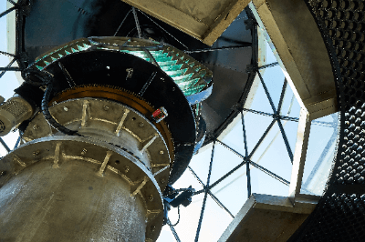
Historically, Fresnel lenses were used in lighthouses, where very large lenses were required, but traditional lenses would have been exceedingly thick and heavy. Nowadays, Fresnel lenses are also used as illumination lenses for camera flashes and viewfinder field lenses in single-lens and twin-lens reflex cameras.

They are also utilized in simpler magnification devices like loupes and magnifying glasses.

Principles of Fresnel Lenses

The grooves on Fresnel lenses are crucial for their optical function, similar to regular optical lenses.

In a conventional curved lens, incident light is refracted to form an image. In contrast, Fresnel lenses use their grooves to refract and focus incoming light. This allows thinner and lighter Fresnel lenses to achieve similar or better light-collecting capabilities compared to traditional lenses.

By adjusting the groove depth and quantity, it’s possible to achieve a shorter focal length than the aperture diameter, a feat not achievable with typical spherical lenses.

The majority of Fresnel lenses are constructed from materials such as glass or resin (acrylic, polystyrene, polycarbonate).

Acrylic Fresnel lenses are popular due to their high transmittance in the visible and ultraviolet spectra, while polycarbonate lenses are used in harsh environments due to their exceptional impact and heat resistance.

Advantages and Disadvantages of Fresnel Lenses

Despite being thinner and lighter, Fresnel lenses have drawbacks in terms of image formation compared to singlet lenses. This is primarily because the grooves on Fresnel lenses are visible, and they introduce diffraction effects, causing light leakage in nearby regions and resulting in blurred images.

However, it’s worth noting that diffraction, although considered a disadvantage in some cases, can be advantageous. Diffractive lenses actively exploit diffraction phenomena for specific applications.

Fresnel lenses and diffractive lenses share similar structures, often leading to confusion, but their underlying physical phenomena differ.

Fresnel Lenses in Illumination

Fresnel lenses find applications in various fields, with LED lighting being a prominent example. In recent years, they have been used as condenser lenses for solar panels, projector screens, optical sensors, and more.

When employed as lighting lenses, Fresnel lenses are often used to emit collimated light by placing a light source at the focal distance position. They are ideal for soft and controlled illumination of specific areas, commonly used in stage lighting and outdoor events.

While they may not match singlet lenses in image formation, they exemplify the use of diffraction to achieve distinct optical effects.

Linear Fresnel lenses are akin to Fresnel lenses for illumination. While Fresnel lenses are spherical with concentric grooves, linear Fresnel lenses are cylindrical lenses arranged in a plane. They are suited for collecting and diffusing light in a single direction, making them suitable for linear light sources.

カテゴリー
category_usa

Fiberscopes

What Is a Fiberscope?

Fiberscopes

Fiberscopes, also called industrial endoscopes or medical endoscopes, are made of many thin glass fibers strung together and fitted with a camera.

A very small digital camera is attached to the tip of the scope, which can be bent and deformed at will. Compared to ordinary intracanal inspection cameras, the diameter of the camera is very thin, yet the image quality is highly accurate and the tip can be freely movable. Even if the fiber is bent, the image transmission is accurate because light travels while reflecting internally.

Because the Fiberscope is integrated with a light source and is clearly visible, it is possible to observe narrow areas and internal details that cannot be seen visually. Because of this, they are more expensive than other types of endoscopes. Generally, the size is from 2.4 mm to 8.5 mm in diameter, and the cable length is from 3 m to 30 mm.

3678_Fiberscopes_ファイバースコープ-1.png

Figure 1. Fiber size

Uses of Fiberscopes

3678_Fiberscopes_ファイバースコープ-2.png

Figure 2. Uses of a fiberscope

Fiberscopes are used to inspect and observe the inside of narrow and intricate structures and pipes that cannot be directly visually checked. Major applications include internal inspection of automobiles, infrastructure development and maintenance, quality control in the manufacturing industry, and disaster relief scopes. In particular, they are used inside pipes and ducts, and in places that are inaccessible to the eye due to the structure of buildings.

In addition, they are also used as medical equipment. For example, endoscopes are used to examine the intestines and stomach. For organs located deep inside the body, it is not possible to see directly with the eye, and if the outer diameter of the camera or tube is too large, there is a risk of hitting the walls of the organ or other parts of the body and damaging the cells. On the other hand, the camera of Fiberscope can be used safely because the tip of the camera can also be freely movable.

Principle of Fiberscope

3678_Fiberscopes_ファイバースコープ-3.png

Figure 3. Structure of a fiberscope

The optical fiber of a Fiberscope consists of a core in the center and surrounding parts called the gladding, which are covered with a film called plastic primary coat. The optical fiber is flexible and can be bent and moved freely, allowing it to move in accordance with the intended use.

Fiberscopes have a structure in which the eyepiece and the objective lens at the tip are connected by thousands or tens of thousands of optical fibers that are focused together, allowing direct visual observation through an image guide made of these optical fiber bundles.

When viewing an object with a Fiberscope, an image of the object is projected on the end face of the objective lens, and the image can be clearly seen by magnifying the image with an eyepiece.

Other Information about Fiberscopes

1. Advantages of Fiberscope

A Fiberscope is a device that uses a thin tube to view the image at the tip. Because of its flexibility, it is also used as a medical endoscope for internal examination of the intestines and stomach by moving the tiny camera and the flexible tip.

For organs deep inside the body, the great advantage is that the tiny size of the camera and tube and the freely movable tip minimize the risk of hitting the walls of internal organs and damaging cells, so they can be used with peace of mind.

2. Disadvantages of Fiberscope

A disadvantage is that the honeycomb structure, which consists of a bundle of thin fibers, may cause a slight shadow of the boundary line. Also, because the image is viewed through the fibers, the longer the fiber is used, the darker it becomes. Another disadvantage is that it can break if too much load is applied. If you try to make the fiber longer, the cost will be higher.

カテゴリー
category_usa

Fume Collectors

What Is a Fume Collector?

A fume collector is a device used to extract and remove fumes generated during welding operations. Fumes consist of solid particles suspended in the air, resulting from the vaporization and solidification of solid materials or chemical reactions in gases. The primary source of fumes is arc welding. Additionally, fine dust produced during grinding processes can also be harmful and necessitates the use of a dust collector.

Welding fumes contain various toxic substances, including iron oxides, silicon oxides, beryllium, cadmium, zinc, lead, and asbestos.

Uses of Fume Collectors

Inhalation of fumes can lead to a condition called pneumoconiosis. Individuals working in environments where inorganic or mineral dust is generated are particularly vulnerable to this disease, primarily due to the inhalation of small dirt particles or metal grains over an extended period. This condition causes lung tissue to become fibrotic, hardened, and lose elasticity. Fume collectors are employed to prevent pneumoconiosis.

Examples of places where fume collectors are utilized include auto body shops, metal fabrication facilities (sheet metal fabrication, laser cutting, welding), and more.

Principles of Fume Collectors

The operating principle of a fume collector closely resembles that of other dust collectors. An impeller is used to create suction, and the impeller is equipped with various filter structures to prevent fumes from adhering to it. Inside the collector, a baffle structure is incorporated to intercept heavy fume particles, ensuring their collection. Subsequently, a wire mesh filter is employed to capture most of the remaining fumes. Fumes that manage to bypass the baffle are also collected by the filter.

To address concerns related to spatter and sparks produced during welding, precautions are taken. Welding sparks, when combined with molten metal particles, can solidify and adhere to nearby metal surfaces. These solidified grains around the weld are known as spatter. To prevent sparks and spatter from entering the dust collector, safety measures are in place to mitigate the risk of fires or malfunctions.

The collected fumes are then removed from the dust collector, often utilizing a pulse jet system that intermittently pulses air to efficiently dislodge and remove the collected fumes.

カテゴリー
category_usa

Power Controllers

What Is a Power Controller?

A power controller is a device that can regulate the amount of power or voltage output and is a type of electronic circuit.

There are different types of power controllers, including power controllers that can control voltage and AC power controllers that can control the current of an AC power source.

Uses of Power Controllers

Power controllers that control output voltage are used to prevent abnormal current, heating, and equipment overwork by controlling voltage.

In the case of AC power controllers, they can control the amount of power output from an AC power source and are used to adjust the amount of power to a desired level.

Uses of power controllers include adjusting the brightness of electric lights, and adjusting the airflow of ventilation fans, electric fans, etc.

Due to the nature of the device itself, some power controllers cannot be used, which may cause malfunctions.

Principle of Power Controllers

Power controllers can be used by connecting the device for which current or voltage is to be adjusted between the power supply and the device, instead of connecting it directly to the power supply, and then adjusting it with the knob part of the power controller, etc.

In the case of voltage control, etc., power controllers use the principle of slidacs or series resistors to adjust the voltage, but with this method, it is not possible to adjust the speed of motors and other devices.

In the case of current control such as AC power controllers, the principle of triac control is used to reduce power by switching on and off the triac element to reduce the AC current partially.

カテゴリー
category_usa

Thermostatic Bimetals

What Is a Thermostatic Bimetal?

Thermostatic bimetals are thermostats (temperature contact devices) that have a function of breaking the circuit by warping the metal and separating the contacts when a certain temperature is reached. This is due to differences in the properties of the two different metals (called bimetals). Thermostats are generally referred to as thermostatic bimetals. This type of thermostat has a long history and does not use semiconductors or other materials that are relatively sensitive to the environment, making it highly reliable.

Uses of Thermostatic Bimetals

Thermostatic thermostats are used in environments where semiconductors, electronic circuits, and sensors are commonly used for temperature protection. The old-fashioned thermostatic bimetal is still used in harsh environments where such sensitive components cannot withstand the harshness of the environment. The reliability of the old-fashioned thermostatic bimetal is still in use today because of their high reliability. As a temperature protection component, the thermostatic bimetal uses only metal materials, making them extremely difficult to break.

Principle of Thermostatic Bimetals

A thermostatic bimetal consists of two or more metal plates with different coefficients of thermal expansion that are laminated together. By applying this property and using the warped part as a contact point for opening and closing, it is possible to turn on and off heat sources and power supplies and to control temperatures. Originally, the thermostat was an open/close device meant to maintain a constant temperature, and it has been used to open and close contact points of sensors, power supplies, heaters, etc., using the difference in warping of two or more pieces of metal due to temperature. The metals used include chromium, manganese, magnesium, and other metals as additives in alloys such as iron and nickel on the high expansion side. Conversely, on the low expansion side, an alloy of iron and nickel with a lower expansion coefficient is used. Ultimately, the main component of the bimetal that operates the contacts both with a high and low expansion coefficient is an alloy of iron and nickel, which is cheap, easy to process, and durable.

カテゴリー
category_usa

Drill Grinding

What Is Drill Grinding?

A drill is a tool used for creating round holes of various sizes in a workpiece. Drill grinding is a process that involves grinding the surface of a drill bit‘s cutting edge to maintain its cutting ability. By rotating the spindle of a processing machine equipped with a drill, the contact surface between the drill and the workpiece is ground away, and chips are removed during the cutting process.

Over time, as a drill is used, wear occurs on the cutting surface. Therefore, it becomes necessary to grind the cutting edge of the drill bit to restore its functionality.

Uses of Drill Grinding

Drills can be classified into four main types: solid drills, attached edge drills, interchangeable edge drills, and interchangeable head drills.

Drill grinding is primarily used for solid drill bits. Drill grinding machines are designed to handle a range of drill bit diameters for grinding. While they are commonly used with small-diameter drill bits, there are also grinders that can accommodate drills ranging from Φ25 to 40. The cutting-edge angle of the drill tip must be adjusted based on the material being processed. For instance, when working with metallic materials, the tip angle is generally ground to 118 degrees.

Principles of Drill Grinding

For drill grinding, an appropriate collet chuck is selected according to the drill diameter. The drill bit is secured in the chuck and positioned for grinding on the grinder. Subsequently, the cutting edge is ground either manually or automatically. Typically, “CBN” abrasive materials are used for drill grinding.

After grinding the drill bit edge, thinning is performed. Thinning involves adding a shape to the tip of the drill core thickness. This process enhances the grip between the cutting edge and the workpiece during drilling, reduces core shake, and allows for more precise vertical hole drilling.

Features of Drill Grinding

Drill grinding is employed to regrind the cutting edges of drill bits that have lost their cutting ability, making them suitable for reuse.

The X type represents a general thinning shape, best suited for working with general materials such as mild steel and plastic.

The XR type, although less effective in bite, is ideal for materials with hardness and viscosity, such as stainless steel, due to its ability to maintain cutting edge strength.

The S type features simple thinning, making it suitable for processing wood and similar materials.

The N type, with a shallow thinning surface and higher cutting edge strength than other types, is particularly well-suited for deep hole drilling.

Additional Information About Drill Grinding

Generally, drill bits with a twist are referred to as drills. A drill consists of a cutting tip, a twisted lead section for chip ejection, and a shank for attachment to a chuck. The sharpness of the cutting edge of a drill bit deteriorates with each cutting operation, often necessitating regrinding using drill grinding techniques.

High-speed steel and cemented carbide are common materials used for drill bits, with the cutting edges frequently coated with wear-resistant coatings.