What Is a Breadboard?
Breadboards are boards designed for easy assembly of electronic circuits. There are two types of breadboards: those that use solder and those that do not require solder.
The type widely known in the electronics industry is the solderless type, which is called a solderless breadboard. The term “breadboard” refers to a solderless breadboard, while the term “universal breadboard” refers to the type that uses solder.
Uses of Breadboards
- Solderless Type
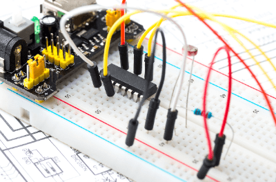
By simply inserting various electronic components and jumper wires into the holes on the board, electronic circuits can be easily built without soldering. Since soldering is not required, components can be easily replaced. This type cannot be used in high-current or high-frequency circuits.
- Type That Uses Solder (Universal Board Type)
The shape is a general universal board, but the pattern is connected from the beginning like a solderless board. The universal board type is used for high current or high-frequency circuits. Patterns vary according to specifications, but wiring man-hours can be reduced.
Principle of Breadboards
- Solderless Type
Conductors are printed on an insulator in a horizontal and vertical arrangement. These are covered with plastic with holes. Holes are drilled into the conductors, and metal sockets are attached to the conductors with holes. Therefore, when a terminal is inserted through the hole, it sticks into the socket and conducts to the conductor. When connecting between terminals, another terminal can be inserted through another hole in the same conductor to make a connection as if the terminals were soldered together.
The hole spacing is generally 2.54 mm, which is the terminal spacing of DIP components, so that DIP components can be mounted as they are.
- Type Using Solder (Universal Board Type)
A universal breadboard has a copper thin film for soldering around the holes. In the universal Breadboard type, multiple holes are connected by a copper thin film. Since the terminals cannot be connected simply by sticking them in the holes, they must be soldered.
To connect between terminals, another terminal can be inserted through another hole in the copper thin film and soldered.
Breadboard Sizes
Breadboards come in a variety of sizes, but the overall size can be varied relatively freely because they can be joined by dovetail grooves. A dovetail groove is a groove with an inverted C-shaped cross section. The dovetail groove is made to be joined to a protrusion (convex rectangular body) that fits into the groove so that it will not come off. However, the position and size of dovetail grooves vary by manufacturer, so it is easier to use the same model number and manufacturer.
Some inferior breadboards have loose dovetail grooves and are difficult to insert and remove, so care should be taken.
Advantages and Disadvantages of Breadboards
The advantage of using breadboards is that they are easy to assemble, as most of them do not require soldering. They are also easy to reuse when making changes or disassembling. Conversely, demerits include the limited number of components that can be handled and the fact that they are not suitable for large circuits because they become confusing when circuits become complex.
Schematics and Wiring Diagrams for Assembly
Schematics and wiring diagrams are used when assembling circuits on Breadboard. They are like blueprints that depict the placement of circuit components and wiring. The difference between a schematic and an actual wiring diagram is as follows:
A schematic is a more specialized diagram that uses symbols to represent components and electrical connections. Symbols are standardized into several standards. By following one of the standards and expressing the symbols correctly, anyone can read them correctly and in the same way.
The actual wiring diagram is a diagram that expresses parts and wiring in more detail. Because it is drawn in the same way as the actual components and overall structure, some diagrams are more like a pictorial representation than a diagram.
Actual wiring diagrams are easier to understand and are suitable for those who are doing assembly work for the first time. On the other hand, if the circuit diagram itself has a large and complex structure, a schematic diagram is more suitable because it is complicated and difficult to understand when expressed in an actual wiring diagram. It is necessary to create a circuit diagram while considering the structure of the circuit to be assembled. (Using an editor or software for drawing schematics and actual wiring diagrams will also help reduce wiring errors, etc.)