カテゴリー
category_usa

Chemical Mechanical Polishing (CMP) Machine

What Is a Chemical Mechanical Polishing (CMP) Machine?

CMP machine is used to polish silicon wafers. Semiconductors are made on a tiny scale, requiring uniform, high-precision polishing. In addition, they have many layers of different hardness, each of which must be polished using the appropriate pressure, abrasives, and chemicals. During polishing, the surfaces and irregularities are chemically reacted and mechanically removed with sandpaper or other tools according to the composition of each semiconductor layer.

Uses of CMP Machines

CMP machines are mainly used in the semiconductor manufacturing process. CMP is used in the semiconductor process to flatten the uneven surface after etching, oxide film formation, ion diffusion, etc. CMP allows for precise flattening and facilitates further layering on the flattened surface. When selecting a CMP system, it is necessary to consider the planarization accuracy, the chemicals and fluids used, and the processing speed of the silicon wafers.

Principles of CMP Machines

This section describes the principle of operation of CMP machines, which are generally large, to process a large number of silicon wafers at a time at high speed. The components are a rotating stage, a polishing section with nozzles for applying chemicals and chemicals, sandpaper, etc. In addition, a robot for transporting silicon wafers, a cleaning section after polishing, and a detection section above are also included.

The essential operation is to spray chemicals and chemical agents onto silicon wafers through nozzles, press sandpaper, etc., onto the wafers, and polish them by rotating the stage at high speed. The targets of chemical polishing are oxide film, tungsten wiring, and copper wiring. In the case of oxide film, the film is dissolved in an alkaline solution and polished with silicon oxide of the same composition. For tungsten wiring, the surface portion of tungsten is oxidized, and the surface is polished with silicon oxide. In the case of copper wiring, the copper is oxidized, then complexed and polished with silicon oxide, etc.

カテゴリー
category_usa

CNC Lathe

What Is a CNC Lathe?

CNC Lathes

A CNC lathe is a conventional lathe equipped with a computer-controlled system that enables automated cutting operations.

The term “CNC” stands for Computerized Numerical Control.

Tool changes are also automated, either through the installation of an ATC (Automatic Tool Changer) device or by selecting the optional ATC device.

Uses of CNC Lathes

CNC lathes, often referred to as unmanned processing machines, are employed to precisely shape parts required in large quantities.

CNC lathes are primarily used for bar processing (bar work) and profile processing (chuck work).

Common processing methods include:

  • Outer diameter machining
  • Internal diameter machining
  • Threading
  • Drilling
  • Grooving

CNC lathes are used for processing a wide range of parts, from precision components like those used in automobiles and aircraft to everyday items such as cookware and tools.

Principles of CNC Lathes

The operation principle of CNC lathes is explained below.

CNC lathes are computer-controlled machines and are not intended for manual operation like conventional lathes.

To perform machining operations accurately, a program must be created based on the part’s design drawings.

Various parameters and commands, such as tool movements and spindle speeds, must be specified based on the part’s design.

These command instructions include tool movement, spindle speed, and other settings.

Computer-aided manufacturing (CAM) software can also be used to create machining programs for CNC machines.

CAM software simplifies the process by generating machine-readable data from 3D CAD models, including toolpath information.

The CNC lathe’s components include a rear spindle, feed mechanism, tool post, guide bush device, spindle (chuck, spindle head), control panel, material supply system, bed, and more.

CNC Lathes vs. Machining Centers

A machining center is a type of machining equipment where the workpiece is fixed to a base, and the cutting tool performs rotational cutting operations. While both CNC lathes and machining centers support numerical control, their machining methods differ.

Currently, “hybrid machines” combine the capabilities of CNC lathes and machining centers.

カテゴリー
category_usa

Chemical Vapor Deposition (CVD) System

What Is a Chemical Vapor Deposition (CVD) System?

A chemical vapor deposition (CVD) system is a device used for thin film growth and surface treatment. CVD utilizes a chemical reaction to deposit substances from the gas phase onto a solid surface, heating the substrate and delivering reactive gases to form films or coatings. This process is highly controllable, and reproducible, and enables precise control of film properties. However, care is needed due to the toxicity of many gases used.

Uses of Chemical Vapor Deposition (CVD) Systems

CVD systems are vital in semiconductor manufacturing, optical coatings, and protective coatings. They are used to create insulating layers, conductive layers, spectral filters, anti-reflective coatings, and protective surfaces on various materials.

1. Semiconductor Manufacturing

In the semiconductor industry, CVD is crucial for creating SiO2 films on silicon substrates, used as gate oxide and insulators, and for forming conductive layers with metals like copper or aluminum.

2. Optical Coatings

CVD is integral to producing multilayer optical filters, reflective mirror coatings for laser beams, and protective lens coatings.

3. Protective Coating

Used for enhancing corrosion and wear resistance on metal surfaces, CVD is employed in surface treatment of cutting tools, sensors, and ceramic materials.

Principle of the Chemical Vapor Deposition (CVD) System

The CVD process involves supplying reaction gases to a heated substrate, where they chemically react and deposit elements and chemicals on the substrate surface. Control of deposition parameters is key to achieving desired thin film characteristics.

Types of Chemical Vapor Deposition (CVD) Systems

There are various CVD systems, each with unique mechanisms and applications.

1. Thermal Chemical Vapor Deposition (CVD) System

Thermal CVD systems react raw material gases at high temperatures either on the substrate or within the vessel to create films. They come in two types: substrate-heated and container-heated.

2. Plasma Vapor Deposition (CVD) System

Plasma CVD systems form films by creating a plasma state of the raw material gas and depositing it on the substrate. They are especially beneficial for semiconductor manufacturing requiring precise dimensions.

3. Optical Chemical Vapor Deposition (CVD) System

Optical CVD systems use light to initiate chemical reactions in the gas phase. They are capable of producing films at very low temperatures compared to other CVD systems.

カテゴリー
category_usa

EMC/RFI Tester

What Is an EMC/RFI Tester?

EMC/RFI Testers

An EMC/RFI tester is a piece of equipment used to perform EMC testing. Let us first explain what EMC stands for.

EMC stands for “electromagnetic compatibility.” In Japanese, it is translated as “電磁両立性 (denji ryōritsu-sei).”

In essence, EMC refers to an electronic device’s ability to coexist without interference from electromagnetic noise it emits and its ability to resist external electromagnetic interference. The noise emitted is considered as “emission,” while the device’s capability to withstand external noise is called “immunity.”

For manufacturers aiming to sell electronic products worldwide, compliance with EMC standards is crucial, as they must meet the regulations of individual countries, often based on laws like the Electrical Appliance and Material Safety Law in Japan and IEC standards in other nations.

EMC testing comprises emission tests to measure the noise levels generated by electronic equipment and immunity tests to assess the equipment’s resistance to external noise.

EMC/RFI testers are employed to conduct these tests.

Uses of EMC/RFI Testers

As previously explained, various types of equipment are used to measure the noise generated by electronic equipment or apply noise to electronic equipment.

This noise measurement or application is performed in an anechoic chamber, a testing environment designed to completely block radio waves. Since official certification is required for these testing laboratories, their availability is limited.

Moreover, the cost associated with certification testing in these specialized laboratories is typically several hundred thousand yen per day. Longer testing times result in higher expenses, posing challenges for electronic equipment manufacturers during development.

Principles of EMC/RFI Testers

As mentioned earlier, EMC testing includes emission tests to evaluate the noise levels generated by electronic equipment and immunity tests to assess noise resistance.

There are two types of emission (noise generation) test methods for electronic equipment: conducted emissions and radiated emissions.

Conducted emissions measure the noise generated by electronic equipment using a specialized noise measurement device known as a LISN (Line Impedance Stabilization Network). Radiated emissions measure the noise received by an antenna. Naturally, these tests are conducted in locations where external noise is entirely blocked out, making the measurement system for these emission testers extensive, including the testing environment.

Next, we will explain immunity testing, where external noise is applied to assess equipment immunity.

The primary types of immunity testing include static electricity tests, square wave impulse noise tests, fast transient burst tests for noise generated by switches and other switchgear, lightning surge tests, and power voltage fluctuation tests (also known as sag or dip tests), among other specialized testing procedures. During these tests, the Equipment Under Test (EUT) is exposed to noise to verify if it can withstand the specified levels.

Only products that successfully pass these EMC tests, conducted with the assistance of EMC/RFI testers, can be officially sold in the market and obtain certifications such as CE marking for Europe.

カテゴリー
category_usa

Frequency-to-Voltage Converter

What Is a Frequency-To-Voltage Converter?

A frequency-to-voltage converter is a device that converts frequency into voltage in direct relation to the rotation or movement speed. This converter is crucial for monitoring and analyzing frequency changes, and its inverse version is known as a VF converter.

These converters are vital in applications such as hybrid and electric vehicle motors and high-speed production lines in manufacturing plants. They effectively measure start-up characteristics, fluctuations in rotation during steady operation, and transient phenomena in flow velocity changes.

Uses of Frequency-To-Voltage Converters

Frequency-to-voltage converters are essential for converting invisible frequency into voltage. When used with an AD converter, they transform analog signals, susceptible to noise, into digital values, facilitating long-distance transmission. Common applications include motor performance tests, rotational fluctuation measurements of engines and motors, and overload-induced performance tests.

Principle of Frequency-To-Voltage Converters

In frequency-to-voltage converters, a decaying pulse signal generates a voltage signal corresponding to the pulse frequency. These converters employ both analog and digital channels for signal processing. A sensor-generated signal creates a gate signal at the comparator, which integrates clock counts during its open/close period. The counter contents are then converted to an analog signal via a D/A converter.

Types of Frequency-To-Voltage Converters

Various types of converters are available, including multi-channel measurement devices and small-amplitude signal detectors for rotational speed analysis. They offer predictive calculations for smooth output during deceleration, aiding in drive unit behavior analysis.

Some models support high input frequencies and wide input amplifier bandwidths, aligning with the trend toward multi-pulse rotary encoders.

Other Information on Frequency-To-Voltage Converters

1. Filtering

These converters come with integrated low-pass filtering or programmable filtering options, allowing selective signal frequency passage based on set thresholds.

2. Rapid Deceleration Tracking Function

Certain frequency-to-voltage converters feature a rapid deceleration tracking function, which halts rotational output if no input is detected for longer than the previous pulse interval during sudden deceleration. The analog output response depends on whether the follow-up function is active or not.

3. Trigger Function

These converters can perform F/V conversion with a one-pulse response proportional to frequency upon receiving a triggerable voltage pulse signal. The trigger level is user-specifiable within a certain range.

4. Linearity

Frequency-to-voltage converters provide a DC voltage proportional to frequency, but linearity can vary across frequency ranges. To maintain linearity, especially in high-frequency bandwidths, some models feature a rapid discharge path for the circuit’s capacitor.

カテゴリー
category_usa

NC Milling Machinery

What Is an NC Milling Machinery?

NC Milling Machinery

NC (Numerically Controlled) milling machinery is a type of NC machine tool used in metalworking. These machines are controlled by an arithmetic device, allowing for automated and precise operations. Machining programs are pre-loaded into the machine, enabling the production of high-precision workpieces. Milling refers to the process where the tool rotates to cut the material.

Uses of NC Milling Machinery

NC milling machines are primarily utilized for metal cutting tasks. Equipped with a computerized NC control system, these machines can process multiple parts uniformly, reducing variations caused by different operators. This capability is particularly valuable for machine tool manufacturers and mold producers who require high-volume, consistent output.

Principles of NC Milling Machinery

The NC milling machine comprises an “NC device” for machine control and an “NC program” for command execution. The NC device is responsible for translating processing instructions into machine movements.

This device includes a panel for operator interactions, a central unit for numerical calculations, a sequencing mechanism for sensor and peripheral device control, and a servo mechanism for precise movement control.

The central part of the NC machine tool employs numerical operations based on the “G code,” a programming language consisting of simple commands and coordinates. The sequencing mechanism ensures the correct operation of sensors and peripheral devices, while the servo mechanism controls the servo motor, directing the machine to the required cutting position and speed.

カテゴリー
category_usa

Numerically Controlled (NC) Lathe

What Is a Numerically Controlled (NC) Lathe?

Numerically Controlled (NC) Lathes

A numerically controlled (NC) lathe is a computer-controlled machine for cutting and processing materials, including metal and plastic, offering high precision and minimizing operator error.

Uses of Numerically Controlled (NC) Lathes

NC lathes are essential in metalworking, automotive, medical devices, and general manufacturing, used for precision parts like cylinder heads, crankshafts, artificial joints, and electronic components.

Principle of Numerically Controlled (NC) Lathes

The NC lathe comprises a lathe section, a computer-controlled section, and an operation section. It includes a motor, spindle, spindle, chuck, and vise, with sensors for precision. Oil reduces friction during cutting.

Types of Numerically Controlled (NC) Lathes

Diverse NC lathe types cater to different manufacturing needs.

1. 2-Spindle Numerically Controlled (NC) Lathe

A two-axis NC lathe that can cut multiple parts simultaneously, ideal for efficient machining.

2. Compact Numerically Controlled (NC) Lathe

Smaller in size, these lathes are suitable for machining fine parts in limited spaces. Desktop models are also used for education and small-scale production.

カテゴリー
category_usa

Acetal Resin

What Is an Acetal Resin?

Acetal resin is a synthetic material blended with polyacetal (POM) resin and graphite. POM resin, a plastic material, is known for its high mechanical strength, wear resistance, and chemical resistance. Graphite enhances these properties by improving friction and heat resistance.

Uses of Acetal Resins

POM is employed in applications that demand wear resistance and self-lubrication, such as industrial machine parts, gears, screws, and sliding components. Its heat resistance ensures that its mechanical strength remains stable even in environments exceeding 100°C. POM is often used as a metal substitute, offering benefits in lightweight design, workability, and productivity. However, its flame resistance, weather resistance, and adhesiveness are low, necessitating careful material selection based on the intended environment. POM is flammable, and it should be noted that plating processes can be challenging with this material.

Principle of Acetal Resins

First, let us explain the manufacturing process of DURACON, a typical example of acetal resin is a copolymer and is synthesized from methanol as a starting point. Formaldehyde synthesized from the oxidation reaction of methanol is trimerized, followed by the polymerization of trioxane.

The trioxane is polymerized with a small number of comonomers as the main monomer to produce crude POM copolymer, which is then shipped with stabilizers, glass fibers, and reinforcing agents added to the crude polymer. Homopolymers, on the other hand, consist of polyoxyethylene chains produced by formaldehyde bonding. Note that homopolymers and copolymers have different properties.

1. Homopolymer POM

Homopolymers are polymers composed entirely of the same monomer unit, with the main chain consisting solely of carbon and oxygen atom bonds.

2. Copolymer POM

Copolymer POM, such as DURACON, comprises two different monomer units. It offers higher thermal stability than homopolymers, making it suitable for more demanding environments. Although acetal resin has excellent oil and alkali resistance, its rigidity and mechanical strength are marginally lower.

Types of Acetal Resin

1. Standard Acetal Resin

Standard acetal resin is the most common type of acetal resin and is composed of pure polyacetal resin. It has high heat and abrasion resistance and stable mechanical properties. It also has excellent dimensional stability, making it suitable for the manufacture of precision mechanical parts.

This type of acetal resin is a widely used product in the automotive industry for components such as gears, bearings, plugs, and valves.

2. Heat-Resistant Acetal Resin

Heat-resistant acetal resin offers improved heat resistance compared to standard types. It withstands high temperatures without deformation or deterioration, making it ideal for automotive parts, electronic devices, and home appliances. This resin type also demonstrates superior chemical resistance, maintaining stable performance against various chemicals. Additionally, its enhanced flame resistance is advantageous for applications where fire safety is a concern, such as in electronic equipment and automobile engine compartments.

3. Low-Friction Acetal Resin

Low-friction acetal resin, a variant of standard acetal resin, includes a friction-reducing agent to enhance its sliding properties. Characterized by a low coefficient of friction, it is particularly effective in applications like sliding parts, bearings, and gears where reduced friction loss is crucial. This improvement not only enhances the energy efficiency of machines but also minimizes wear risks.

カテゴリー
category_usa

Polyphenylene Sulfide (PPS) Resin

What Is a Polyphenylene Sulfide (PPS) Resin?

Polyphenylene Sulfide (PPS) Resins

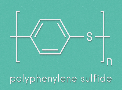
Polyphenylene sulfide (PPS) resin is a thermoplastic resin characterized by a structure of alternating benzene and sulfur bonds. It is esteemed as a super engineering plastic due to its outstanding properties. The mechanical strength and other characteristics of PPS can be modified with different fillers, leading to its widespread use as a reinforced resin, typically with about 30% glass fiber composites.

Its growing popularity across various industries stems from its well-balanced properties, including excellent moldability, processability, heat resistance, mechanical strength, dimensional stability, flame resistance, and chemical resistance.

Uses of Polyphenylene Sulfide (PPS) Resins

PPS resin, a super engineering plastic, is utilized in automotive parts, electronic parts, and medical equipment parts, among other high-performance applications. Notably, nearly half of the PPS resin market is dedicated to automotive parts.

As hybrid vehicles increasingly employ PPS resin components, its demand is expected to rise. In non-automotive sectors, PPS is essential for electronic components like IC chips, due to its superior dimensional stability and insulation properties. Its excellent heat and flame resistance makes it ideal for filter manufacturing as well.

Principle of Polyphenylene Sulfide (PPS) Resins

PPS resin is typically produced by a polycondensation reaction of paradichlorobenzene and sodium sulfide in a polar solvent, under high temperature and pressure. The polymerization process involves dehydration and dephosphorization reactions. Cross-linking in the resulting polymer greatly influences its properties, making the distinction between cross-linked and linear PPS resin critical for various applications.

1. Crosslinked Polyphenylene Sulfide (PPS) Resin

Crosslinked PPS resin, formed by heat treatment in an oxygen atmosphere during synthesis, allows molecular weight control by incorporating oxygen into the polymer chain. This results in a cross-linked structure with high rigidity and creep deformation resistance, even in high-temperature environments.

2. Linear Polyphenylene Sulfide (PPS) Resin

Linear-chain PPS resin retains its linear structure without undergoing special heat treatment. This type of PPS has lower rigidity but improved toughness and elongation compared to cross-linked PPS. It allows for high-purity synthesis and achieves superior moisture absorption resistance, electrical insulation, and dimensional stability.

Types of Polyphenylene Sulfide (PPS) Resin

1. Unreinforced Polyphenylene Sulfide (PPS) Resin

Unreinforced PPS consists purely of PPS resin without additional reinforcing materials like glass or carbon fiber. It’s widely used across various industries thanks to its impressive properties, especially its remarkable heat resistance. Unreinforced PPS maintains stable performance even under high temperatures, making it suitable for high-temperature industrial applications such as engine parts, exhaust system components, and boiler parts.

2. Reinforced Polyphenylene Sulfide (PPS) Resin

Reinforced PPS resin, created by adding materials like glass or carbon fiber to PPS, offers enhanced strength and rigidity. It’s ideal for components needing impact resistance. In the automotive sector, it’s used for engine parts, exterior parts, and suspension components, where durability and rigidity are paramount. Its excellent performance under severe conditions like high temperatures, vibration, and friction makes it especially valuable.

3. Polyphenylene Sulfide (PPS) Resin for Electrical and Electronic Applications

This type of PPS resin, known for high electrical insulation, is crucial in the electrical and electronics fields. It’s used in printed circuit boards, connectors, terminal blocks, motor parts, transistors, and IC packages. Suitable for high-temperature operations, it maintains stable electrical properties under such conditions and offers excellent chemical resistance.

4. Alloy-Reinforced Polyphenylene Sulfide (PPS) Resin

Alloy-reinforced PPS is a blend of PPS with other materials to enhance specific properties, making it suitable for applications that require lubricity and wear resistance. By incorporating elements like graphite and mineral fillers, this variant improves friction and wear resistance. It’s particularly effective in automotive and mechanical parts that endure high friction and temperatures.

カテゴリー
category_usa

PTFE Product

What Is a PTFE Product?

PTFE Products

PTFE products (polytetrafluoroethylene) are resins where fluorine atoms replace hydrogen atoms in polyethylene. Their strong carbon-fluorine bonds provide high resistance to heat and chemicals. These properties make PTFE products ideal for tubes and gaskets in extreme conditions, such as high temperatures and chemical exposure.

PTFE’s non-adhesive and abrasion-resistant qualities also make it a popular coating for cookware. However, compared to other fluoropolymers, PTFE has lower processability due to its high viscosity and low thermal fluidity when melted.

Uses of PTFE Products

PTFE products exhibit abrasion resistance, non-adhesiveness, chemical resistance, and heat resistance. They are commonly used as coatings in cookware, typically referred to as “fluorine-coated.” Additionally, PTFE finds industrial applications in hoses, gaskets, tubes, and insulating materials, suitable for high-temperature and corrosive environments. However, PTFE’s high melt viscosity limits its molding capabilities, making it less processable than other fluoropolymers.

Structure of PTFE Products and Resin Manufacturing Methods

PTFE’s chemical structure is polyethylene with fluorine replacing all hydrogen atoms. This structure contributes to its heat and chemical resistance. In contrast, PTFE’s moldability and processability are inferior to other fluoropolymers. For example, PFA becomes fluid when heated, allowing for various shaping methods like injection molding. PTFE, however, remains highly viscous above its melting point and lacks fluidity. PTFE products are typically formed by compression molding the powder and sintering it above the melting point.

Difference Between PTFE and Teflon

“Teflon” is a term often confused with PTFE. Teflon is a registered trademark of DuPont, initially used for commercializing PTFE. Today, teflon refers to a range of fluoropolymers, not just PTFE, including FEP, PFA, and modified types. These fluoropolymers differ in adhesive strength, insulation properties, and chemical resistance, necessitating careful selection based on the application.

Heat Resistance and Safety of PTFE Products

PTFE is generally safe for oral ingestion, and no health effects are reported even if flakes from cookware coatings are consumed. However, PTFE can decompose into toxic compounds at temperatures above 350°C (350°F). Instances of respiratory problems have been reported due to accidental overheating, such as leaving a pot on a fire unattended or burning PTFE in a laboratory. Although PTFE is harmless under normal conditions, caution is necessary to avoid harmful decomposition products from prolonged direct exposure to fire or extreme heat.