カテゴリー
category_usa

Clock Generators

What Is a Clock Generator?


A clock generator is a circuit that generates clocks of multiple frequencies from a single source clock signal. Generally, the frequency range generated is from a few KHz to several GHz.

Uses of Clock Generators

Clock generators are mainly used in the following applications:

1. CPUs

Clock generators are most commonly used in CPUs, which form the core of computers, where many registers and other memory elements are located and to each of them a clock signal generated by a Clock Generator is connected.

Depending on the increment of the clock signal, the output from each storage element passes through various logic and arithmetic circuits and is input to the next stage of storage elements. This circuit structure is called a synchronous circuit, and the Clock Generator is responsible for triggering and synchronizing the operation of the synchronous circuit.

2. Digital Devices

Clock generators are used not only in CPUs but also in digital devices such as TVs, smartphones, and DVDs, as well as in general home appliances and industrial equipment controlled by microcontrollers.

The clock is responsible for transmitting timing to each electronic device, and each device operates as a whole by performing its own operations at that timing. Clock generators, which can accurately oscillate signals in a wide range of frequencies, are indispensable devices for the operation of a variety of electronic equipment.

In recent years, the demand for high-quality video and music has increased, and high-quality, expensive clock generators have been commercialized to meet such needs. In particular, when data is exchanged between devices with different sampling frequencies, it is necessary to synchronize the devices with a clock generator to prevent noise contamination due to missing data.

Principle of Clock Generators

Clock generators basically consist of a resonance circuit and an amplification circuit.

A crystal oscillator is often used as the resonance circuit. Quartz oscillators are also used in quartz clocks and make use of the piezoelectric effect, in which a quartz crystal produces an oscillating output with a natural frequency when a voltage is applied. The natural frequency varies depending on the physical characteristics of the crystal, such as its shape and which crystal cross section it is cut from, but an oscillator with the required natural frequency can be obtained using high-purity synthetic quartz crystals.

Since this oscillation waveform is a sine wave, the clock generator shapes it into a square wave so that it can be used in digital circuits. In the generator, a frequency divider circuit and a multiplier circuit generate a clock signal with a frequency M/N times the original frequency (M and N are natural numbers), which is amplified by an amplifier circuit for output.

How to Select a Clock Generator

Clock generators differ not only in the frequency range to be generated but also in the supply voltage and the rise/fall time of the square wave, and should be selected according to the intended use.

One such point is clock jitter. Clock jitter is the fluctuation of each square wave along the time axis and is an indicator of how well the clock continues to transmit an orderly frequency, so it must have a low jitter.

There are two types of jitter: jitter seen between rising edges and jitter seen between falling edges, etc. By carefully examining the jitter according to the application, a higher quality system can be pursued.

Other Information on Clock Generators

Clock generators using MEMS oscillators are an emerging technology. MEMS oscillators are used for oscillators.

Unlike quartz crystals, which have their own frequency, MEMS oscillators can be programmed with a frequency at the final stage of the manufacturing process, which has the advantage of reducing costs and lead time. In addition, MEMS oscillators are said to be superior to quartz oscillators in terms of quality and reliability, such as the ability to suppress changes in temperature characteristics by incorporating an internal temperature sensor compared to quartz crystals.

カテゴリー
category_usa

Rotary Switches

What Is a Rotary Switch?

Rotary Switches
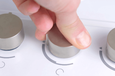
A rotary switch is a switch that switches contact points by turning.

Rotary switches are used for volume control of audio components, knobs of microwave ovens, etc. Most rotary switches are used to switch multiple contacts, but they are sold with only one contact. Most rotary switches are used to switch multiple contacts, but switches that switch only one contact are also available. Recently, ultra-compact rotary switches have been developed, contributing to the miniaturization of audio equipment and other devices.

Uses of Rotary Switches

Rotary switches are used in a wide range of applications, from familiar home appliances to industrial equipment.

Specific applications are as follows:

  • Volume control of audio components
  • Setting the output of microwave ovens
  • Switching power and strength of electric fans
  • Switching the volume of measuring machines and communication equipment
  • Switching of control board settings for inverters, air conditioners, etc.

Recently, pendant lights that use a single-contact rotary switch to operate the power supply are also available to create a retro atmosphere. Also, in recent years, they are sometimes used as power switching switches for portable LED lighting as part of DIY projects.

Principle of Rotary Switches

A rotary switch consists of a sliding element, a case/fixed contact, and a terminal.

The sliding element moves simultaneously with the movable contacts and switches the contacts according to the operation. The switched contacts conduct two or more fixed contacts attached to the case. The contact output of the fixed contacts is output to the outside through the terminals.

Types of Rotary Switches

There are two types of rotary switches: non-shorting type and shorting type. Proper selection is necessary because the circuit may break down if an inappropriate type is chosen for the intended use.

1. Shorting Type

The shorting type is a type in which two or more contacts conduct simultaneously when switching contacts. It is characterized by the fact that there is no moment of circuit breakdown. Therefore, a temporary state of electrical connection between contacts occurs.

This type is used when temporary disconnection is unacceptable, such as in the tap-switching circuit of a transformer. The shorting type is also called make-before-break. In English, it means “connected before the contacts are separated.”

2. Non-Shorting Type

The Non-Shorting Type is a type in which adjacent terminals are completely independent of each other, and the circuit is disconnected once when the contacts are switched. In this type, when switching contacts, both contacts are electrically disconnected for a moment.

Therefore, this type is used when temporary disconnection due to switching is not a problem. In general applications, the non-shorting type is used in most cases. The non-shorting type is also called break-before-make. In English, it means “to leave before the contacts are connected.

Other Information on Rotary Switches

1. How to Use a Rotary Switch

Rotary switches are used to switch circuits by rotating the actuator. They are often used to set up digital circuits. They are used when the switching frequency is not high, for example, for setting purposes.

There are various types of rotary switches, such as those with flat actuators or shaft-shaped actuators. Depending on the shape, some products can be operated with a finger, while others require a screwdriver or similar tool.

2. Thumb Rotary Switch

Among rotary switches, there are thumb rotary switches. This is a rotary switch that uses a disk-shaped part with numbers written on the switch display. They are characterized by their ease of visual confirmation and are used for setting channels on old radio equipment.

A typical thumb rotary switch consists of parts such as a case, pushbutton, slide, rotor, printed circuit board, and mounting plate.

カテゴリー
category_usa

Wavelength Meters

What Is a Wavelength Meter?

A wavelength meter measures light’s wavelength, offering higher sensitivity than optical spectrum analyzers due to its narrow dynamic measurement range. While optical spectrum analyzers provide broader functionality, wavelength meters focus solely on measuring wavelengths, making them more affordable. The measurement reflects the wavelength in a vacuum, with a minor discrepancy from air measurements due to the air’s refractive index.

Uses of Wavelength Meters

Wavelength meters are vital for tasks requiring precise wavelength accuracy, such as characterizing optical components, measuring narrow-bandwidth light sources like lasers and LEDs, and evaluating light in optical fiber communications. They are especially common in measuring light between 1,000 and 1,800 nm, critical for optical fiber communications.

Principle of Wavelength Meters

Wavelength meters utilize physical light interference, employing Fizeau or Michelson interferometers to measure wavelength. These interferometers create interference fringes from light beams, unique to each wavelength and the optical path difference. The wavelength is calculated based on the known optical path difference and the interference pattern observed.

Other Information on Wavelength Meters

1. Wavelength Meter and Optical Fiber Communications

Essential for optical fiber communications, wavelength meters measure the 1,500 nm band, the most efficient for minimizing light loss. As the demand for bandwidth increases, wavelength meters now often measure multiple wavelengths simultaneously, with advanced models handling up to 1,024 wavelengths to support wavelength multiplexing technologies.

2. Applications Beyond Optical Fiber Communications

Wavelength meters also serve in semiconductor laser evaluation for optical communications, with models that rapidly assess single wavelengths on production lines. Additionally, they support measurements in bands below 1,000 nm for optical fiber amplifiers and cater to applications like optical coherence tomography in ophthalmology and fluorescence observation in biotechnology, with models covering 300 nm to 1,200 nm.

3. Compatibility With CW and Pulsed Light Sources

Some wavelength meters accommodate both continuous wave (CW) and high-speed pulsed light sources, which are crucial for various laser applications. It’s important to select a model based on its compatibility with the intended light source.

カテゴリー
category_usa

Flyback Transformers

What Is a Flyback Transformer?

A flyback transformer is a transformer used in a flyback converter.

It is one of the circuit methods used in isolated switching power supplies such as isolated DC-DC converters and AC-DC converters, and other types include the forward method, LLC resonance method, and push-pull method.

In the flyback method, energy is repeatedly accumulated and released into the transformer during power conversion. Therefore, unlike other types of transformers, flyback transformers must have the characteristics to store large amounts of energy.

Uses of Flyback Transformers

Flyback transformers are used in switching power supply circuits used in a variety of consumer and industrial applications. The power that can be handled by this power supply is only a few tens of watts, making it suitable for relatively low-power applications compared to isolated switching power supplies of other methods.

On the other hand, it features a wide input voltage range. It has the advantage of simple power supply circuit configuration, fewer components, and lower cost. However, the peak current is higher, so care must be taken with specifications when selecting switching elements, rectifier diodes, and other components.

Also, the ripple current is higher than in other methods, so the smoothing capacitor capacity must be larger.

Principle of Flyback Transformers

Flyback transformers are based on the principle of charging when current flows through the primary side of the transformer and discharging through the secondary side of the transformer after the current is interrupted. Due to the principle of operation, it is very important for the transformer to accumulate electromagnetic energy in terms of its characteristics.

A switching element (power transistor, power MOSFET, etc.) is connected to the primary side of the flyback transformer, and a smoothing capacitor is connected to the secondary side through a rectifying diode. The polarity of the windings is reversed so that when an excitation current is applied to the primary side of the transformer, a voltage is generated in the direction that the rectifier diode on the secondary side turns off.

When the switching element is turned on, the excitation current flows in the primary side of the transformer and electromagnetic energy is stored in the transformer. When the switching element is turned off in this state, the excitation current on the primary side is interrupted, the direction of the voltage on the secondary side is reversed, and the electromagnetic energy stored in the transformer is released through the rectifier diode. This is smoothed by a capacitor to output a DC voltage.

The flyback transformer must store a large amount of electromagnetic energy. Transformers intended for energy transmission, like other methods, use core materials with high magnetic permeability to increase the coupling coefficient. However, such materials usually cannot store large amounts of electromagnetic energy. Therefore, in flyback transformers, an air gap is created in a part of the core where the magnetic permeability is low, and energy is stored in this gap.

Other Information on Flyback Transformers

1. Difference Between Flyback and Forward Power Supplies

Flyback power supplies require a relatively large transformer because electromagnetic energy must be stored in the transformer. A minute gap is created in part of the core to lower the magnetic permeability and store electromagnetic energy. On the other hand, forward power supplies do not require such a minute gap because the transformer does not need to accumulate electromagnetic energy, and the transformer can be made smaller.

In addition, flyback power supplies do not require isolation separation of the primary and secondary feedback circuits, making the circuit configuration very simple, whereas forward power supplies require isolation and a voltage feedback circuit from the output.

2. Ferrite Material Used in Flyback Transformers

Flyback transformers are widely used in AC-DC switching power supplies due to their configuration. However, the semiconductor devices for switching and the transformer are the two areas of high loss in AC-DC switching power supplies. During high-speed switching operations, rapid magnetic flux changes occur in the transformer, and if an iron core is used for the transformer core, heat is generated due to eddy current losses, rendering the transformer unusable.

For this reason, flyback transformers for high-frequency AC-DC switching power supplies often use ferrite as their core material. Since the characteristics of ferrite are frequency and temperature dependent, it is important to select a flyback transformer with a core made of ferrite material suitable for the desired operating speed.

カテゴリー
category_usa

VME Boards

What Is a VME Board?

VME (Versa Module Europe) boards were developed as boards that use the VME bus, a bus for CPUs.

The VME bus used in VME boards was originally developed for Motorola’s 68000 series CPUs, and was later adopted as a global technical standard by the IEC (International Electrotechnical Commission) and It was later standardized as a technical standard by the IEC (International Electrotechnical Commission) and IEEE (Institute of Electrical and Electronics Engineers: a standardization organization in the electrical and information fields).

It is currently used as a standard bus for 64-bit CPUs in addition to 16-bit and 32-bit CPUs.

Usage of VME Boards

A VME board has 9 or 20 VME connectors on the motherboard, which is the foundation for connecting multiple VME boards.

This motherboard is called a VME backplane board or VME backplane chassis, and its material and size are determined to maintain its performance and quality.

The VME backplane board is very important because it electrically and structurally connects multiple VME boards through which data is transmitted and received.

CPU boards and IO boards are inserted into slots on the VME backplane board.

Principle of VME Boards

The data transfer used on VME boards is based on the asynchronous inter-clocking method, which means that data is transmitted in synchronization with the system clock. This is different from the method of sending and receiving data synchronized with the system clock.

The master side repeats data transmission and does not complete the data transfer cycle until the slave side responds with an acknowledgement signal indicating that data reception is complete.

This is advantageous and easy to design for peripheral devices that do not have sufficient transfer speed, since data can be sent and received according to the timing of the slave device.

However, it is necessary to avoid infinite transfer cycles from the master. For this purpose, the VME bus has a timeout function.

The VME bus is also designed to handle data collisions between devices on the VME bus. An arbitration module is defined as a dedicated functional module for detecting and responding to collisions, and it must be present in every VME bus system.

Two methods are defined for detecting and responding to collisions. These are the round-robin method and the priority method.

Round Robin Method

Round-robin is a method in which each device on the VME bus is sequentially assigned a number based on the number assigned to the device. For example, if there are devices A, B, and C, and the first round is A, B, and C, the second round is B, C, and A, and the third round is C, A, and B. This method determines which device has priority in the event of a collision based on the rule of sequential equal priority switching.

Priority Order Method

On the other hand, the priority method determines which device has priority in the event of a collision based on a fixed priority order for each device.

Depending on which method is adopted is determined according to the system’s application and characteristics.

Other Information on VME Boards

1. Bus

The bus mentioned in the above explanation refers to a circuit that transmits data and signals inside a computer. Inside a computer, devices such as CPU, memory, and IO devices are connected by a common bus.

There is an address bus for transmitting memory address signals and a data bus for data transfer between the CPU and memory/IO devices. There is also a control bus for controlling these two buses. The control bus is responsible for controlling the timing of actual input/output by the address bus and data bus.

2. Bus Standard

The initial development standard was a 16-bit bus standard to fit into the Eurocard connector. Later, through expansion, the current VME64 has a 64-bit bus standard and a 32-bit bus standard.

カテゴリー
category_usa

Illuminance Meters

What Is an Illuminance Meter?

Illuminometers

An illuminance meter is a machine that measures the brightness of a place.

In our daily lives, schools, workplaces, etc., it is necessary to have appropriate illuminance in our work environment. Illuminance is expressed in units of lux. There are two types of illuminance meters: the photocell type, which does not require a power supply, and the photoelectric tube type, which can measure illuminance down to low levels.

Principle of Illuminance Meters

An illuminance meter measures and quantifies the brightness of a lighted area, measuring the luminous flux per unit area (lm: lumens). The illuminance meter’s sensitivity to light wavelengths matches the sensitivity of the human eye, and it obeys the cosine law for light emitted at an angle. The cosine law is a law that states that the luminous intensity Iθ from an evenly diffused area to a certain direction is proportional to the cosine of the angle θ formed with the luminous intensity in the direction normal to this area. This can be expressed in terms of a conductor as follows.

Iθ = In cosθ

The light-receiving part of the illuminance meter consists of a photodiode that converts light into an electrical signal, an optical filter to match the sensitivity of the human eye, and a diffusing globe to follow the cosine law.

Regarding the sensitivity of the human eye, with a peak at 555 nm, the sensitivity of 380 to 780 nm, with a mountain-shaped wavelength selection in the region of 380 to 780 nm.

Therefore, illuminance (lux) itself is also detected within this range.

How to use an Illuminance Meter

The illuminance meter is very easy to use. Just press the measurement button on the illuminance meter, and the measured value will be displayed. Most illuminance meters are large enough to be easily carried by hand and can be easily used in a variety of situations. However, depending on how you use the meter, you may not get the correct measured value.

The following are points to be considered when using these instruments.

1. Effect of Reflected Light

Illuminance meters are affected not only by direct incident light from the light source but also by reflected light. Since the illuminance meter can be affected by reflected light from the hand, face, and clothing of the person being measured, it is necessary to take measures such as bending down as much as possible and wearing clothing with low reflectance.

2. Size of a Light Source to be Measured

When the light source of a filter-type illuminance meter is a narrow beam of light, the path of light reaching the light-receiving element varies depending on the angle, which affects the measured value. When measuring a spotlight that is smaller than the illuminance receiving area of the illuminance meter, care should be taken to consider a different measurement method.

3. Distance between Light Source and Illuminance Meter Receiver

In filter-type illuminance meters, the closer the distance between the light source and the illuminance meter is, the more the light incident on the illuminance meter is angled, resulting in an error. Normally, a distance of about 1 m or more from the light source to the illuminance meter is sufficient to avoid problems.

In addition, standards and measurement methods are established when checking for a safe and comfortable environment in schools, workplaces, factories, and other places. It is necessary to understand the purpose of use and measurement conditions of the measuring instruments and to use them correctly.

Types of Illuminance Meters

Various types of illuminance meters are based on measurement range, accuracy, and ease of use.

Analog illuminance meters are used to simply check the light intensity of fluorescent lamps and the like. They are also used when you want to fix them to a specific location and measure them periodically.

Digital illuminance meters have a wide measurement range and are useful for measuring various locations, such as indoors and outdoors. There are types with separate light-receiving and display sections, which are useful when the measurement locations are far apart. They can be used for a wide range of applications.

As for the measurement range, the range that can be measured differs from illuminance meter to illuminance meter, but some types can switch the specific range in stages.

カテゴリー
category_usa

3D Printers

What Is a 3D Printer?

3D Printers
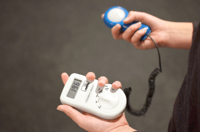
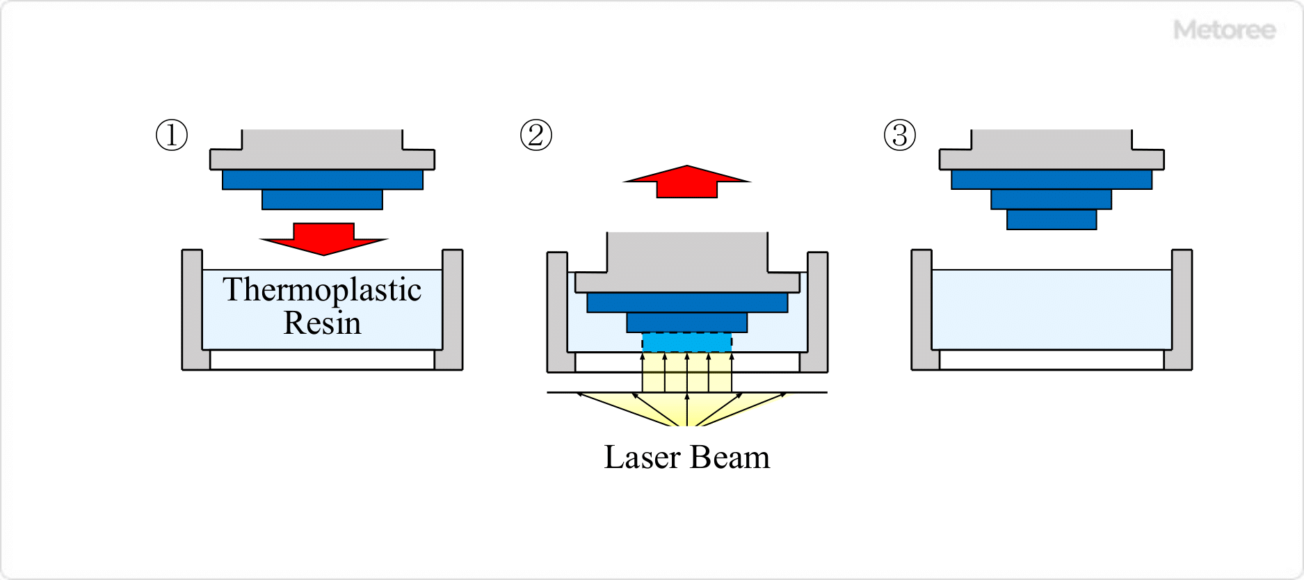
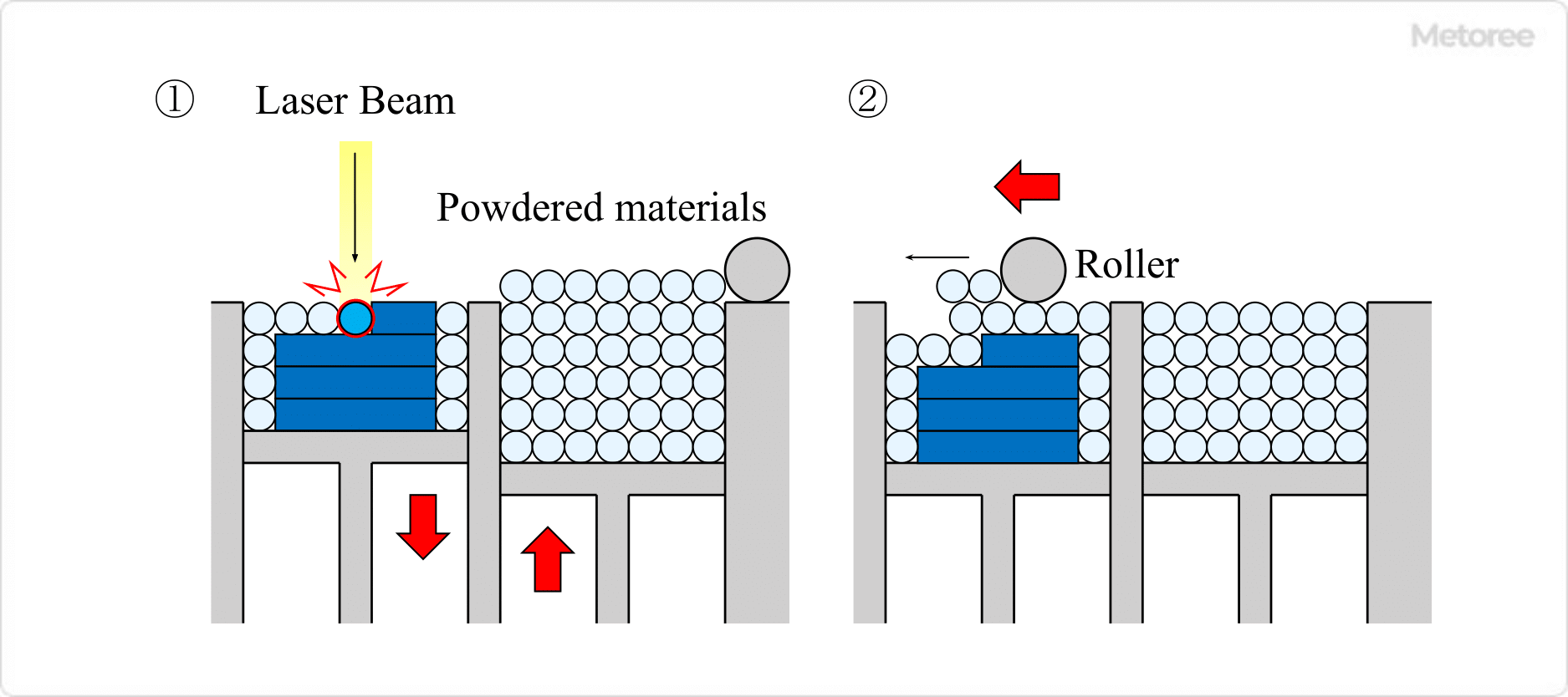
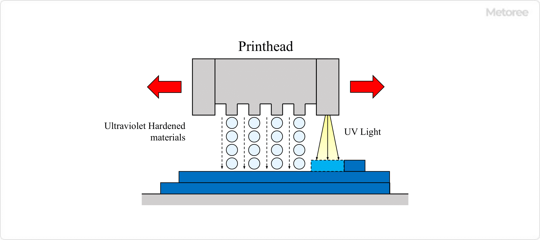
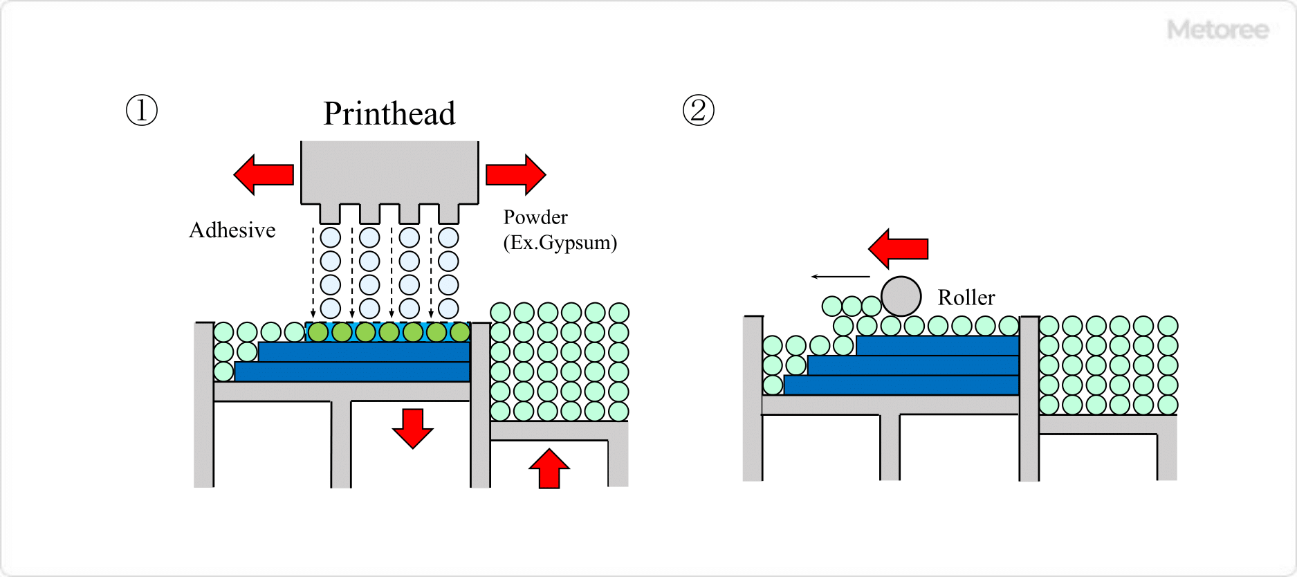
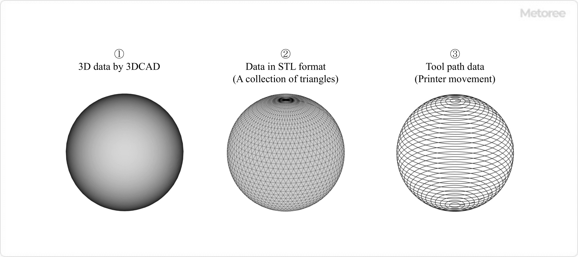
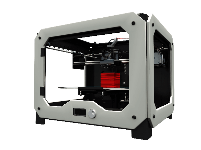
A 3D printer is a device that produces three-dimensional objects by layering printed cross sections based on 3D data.

3D printers can be produced using a variety of methods, including the FDM (fused deposition modeling) method, SLA (stereo lithography) method, SLS (selective laser sintering) method, inkjet method, inkjet powder laminate method, and inkjet powder laminate method. 

For home use, two types of 3D printers are often used: “thermal melting lithography method” and “optical lithography method.”

Applications, Principles, and Advantages of Each Type of 3D Printer

1. Fused Deposition Modeling Method (FDM)

Uses
Production of figures, models, etc.

Principle
Thermoplastic resin is ejected through a thin nozzle of around 0.5mm to print.

Advantages

  • Inexpensive main unit
  • Printing is possible at low cost due to inexpensive materials
  • Mainstream as 3D printer for general use

Disadvantages

  1. Requires support materials
  2. Appearance of the modeled object deteriorates due to stacking marks generated during printing

Printable Materials
PLA resin, ABS resin, etc.

3D-Printers_3Dプリンター-1

Figure1. Thermal Melting Lamination Method

2. Stereolithography Method (SLA) 

Uses
SLAs are used for the creation of mock-ups, stage props, etc.

Principle
Printing is performed by exposing a light-curing liquid resin to light to cure it.

Advantages
Easy to process after modeling, and transparent printed materials can be created.

Disadvantages

  • Printed materials are vulnerable to sunlight
  • Time-consuming post-processing of printed materials

Printable Materials
Epoxy resins, acrylic resins, etc.

3D-Printers_3Dプリンター-2

Figure2. Optical fabrication method

3. Selective Laser Sintering Method (SLS)

Uses
Parts for industrial equipment and medical implants

Principle
Printing is performed by repeating selective heating and sintering of powdered materials one layer at a time.

Advantages
Large-scale, strong structures can be printed without the need for support materials

Disadvantages

  • Equipment, including the printer itself, is expensive
  • Printed materials have rough surfaces.

Printable Materials
Nylon, metal materials such as titanium, etc.

3D-Printers_3Dプリンター-3

Figure3. Powder Sintering Additive Manufacturing Method

4. Inkjet Method

Uses
Manufacture of medical parts and small-lot products

Principle
UV-curable material is placed on a two-dimensional surface as if it were printed by an ordinary printer and then cured by UV irradiation to produce a print.

Advantages
Easy installation and high-resolution printing

Disadvantages
Printed materials are brittle and vulnerable to sunlight.

Printable Materials
Epoxy resin, acrylic resin, ABS resin, etc.

3D-Printers_3Dプリンター-4.

Figure4. Inkjet method

5. Inkjet Powder Lamination Method

Uses
Medical parts, small lot product manufacturing

Principle
Printing is performed by placing an adhesive on plaster and allowing it to cure. Color structures can be created by using colorants.

Advantages
Easy installation and high-resolution printing

Disadvantages
Printed materials have low strength

Printable Materials
Plaster, resin, metal, sand, etc.

3D-Printers_3Dプリンター-5.

Figure 5. Inkjet powder lamination method

How to Use a 3D printer

3D printers can be used to layer the designed structure by melting the resin.

This section explains what you need to prepare and the actual procedure.

What You Need to Prepare

  • Personal computer
  • 3D printer
  • 3D CAD software for designing three-dimensional CAD drawings
  • Slicing software
    Slicing software has the ability to convert 3D data into tool path data.
  • Filament
    Filament is a material to be laminated; its type varies depending on the 3D printer’s lamination method, but PLA resin and ABS resin are most commonly used by beginning users.

Steps to Layering a Structure on a 3D Printer

    • To laminate a structure, create 3D data by using 3D CAD software.
    • Convert the 3D data to STL format so that the 3D printer can read the data.
    • Convert STL data to tool path data.
    • Activate the 3D printer.
    • Remove secondary materials that are welded to the structure as support materials.
    • Surface treatment of burrs, etc. for a smooth finish.

3D-Printers_3Dプリンター-6

Figure 6. Conversion from 3DCAD data to tool path data

Filament Materials That Can Be Handled

3D printers are limited in the materials they can handle, depending on the type of equipment and the melting method of the material.

For example, a 3D printer that can handle resins can handle both general soft and hard resins. Some types of 3D printers can handle a wide range of materials.

Here, we will focus on resin and metal as filament materials that can be handled.

Resin Filament

The most commonly used types of resin filaments for both beginners and advanced users are PLA and ABS resins.
Other resin materials include nylon, plaster, rubber, and epoxy-based materials.

  • PLA Resin
    This resin is synthesized from recycled materials consisting of polylactic acid, which is mainly made from corn, etc.
  • ABS Resin
    A synthetic resin composed of acrylonitrile, butadiene, and styrene.

Metal Filament

Types of metal filaments include stainless steel, brass, titanium, platinum, silver, and gold.

Other special materials include filaments containing bronze as a powder.

カテゴリー
category_usa

Media Converters

What Is a Media Converter?

Media Converters
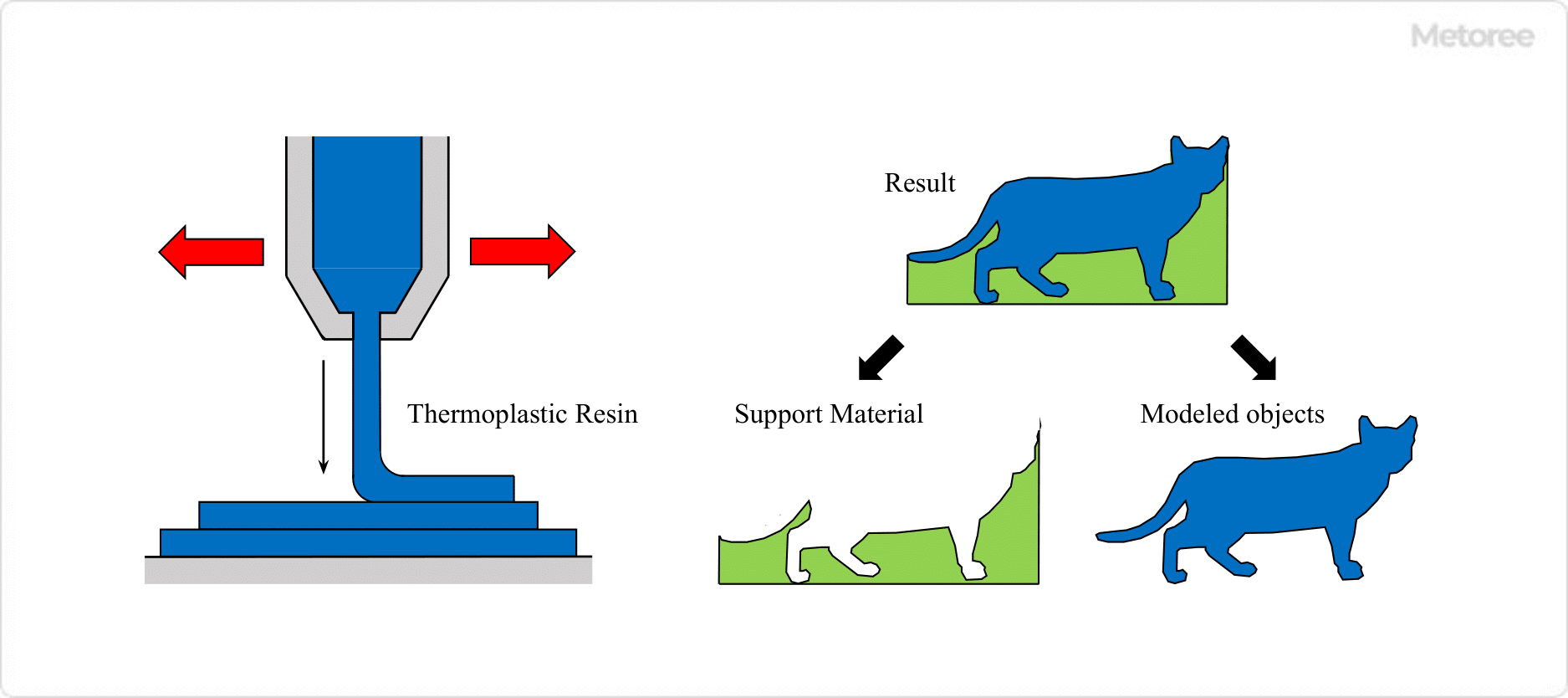
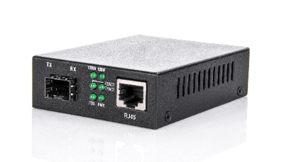
A media converter is a device for connecting a metal cable, which transmits information using electrical signals, and an optical fiber, which transmits information using light as the medium.

A media converter is a device for mutually converting signals in different media, but the media used here are limited to electrical and optical signals. In other words, a media converter is a device that converts electrical signals into optical signals and optical signals into electrical signals, and is also called an optical media converter or MC.

Uses of Media Converters

Media converters are used to connect metal cables, which transmit information using electrical signals, and optical fibers, which transmit information using light as the medium. Metal cables that transmit electrical signals are susceptible to electromagnetic noise as well as signal attenuation as the transmission distance increases. Therefore, the transmission distance is limited to about 100 m.

On the other hand, transmission of optical signals by optical fiber is not affected by electromagnetic noise and is less susceptible to signal attenuation, making it ideal for transmission over long distances. However, since the signal medium is different between metal cables, which transmit signals based on voltage changes, and optical fiber, which transmits signals based on light flashes, the signals must be converted to each other in order to connect the two.

Therefore, a network line that takes advantage of the strengths of each cable is constructed by intervening media converters and mutually converting the two types of signals.

Principle of Media Converters

Typically, a pair of media converters is installed at both ends of an optical fiber connecting two networks built with metal cables. The first media converter converts the electrical signals of the metal cable to optical signals of the optical fiber. The electrical signal input to the media converter is transmitted to a light emitting device such as a laser diode, and output to the fiber optic cable as an optical signal modulated in response to the signal.

The second media converter converts the sent optical signal into a change in voltage by means of a light-receiving element and restores it to the original electrical signal. This mechanism enables reliable signal transmission over long distances using an optical fiber between the two networks.

Media converters can also be classified into the following two types according to the way packet signals are processed.

1. Repeater Type

This type is characterized by the fact that the transmission speed of the electrical signal side is equal to that of the optical signal side. When the communication speeds are the same, conversion can be performed without delay. In other words, when a media converter receives a packet of electrical signals, it immediately converts it into optical signals and outputs them regardless of their contents.

There is no signal delay time, making this mechanism suitable for applications where transmission speed is critical and signal delays are not tolerated. In addition, any packet can be used regardless of the communication protocol, as it passes through without modification. Even if an error packet exists, it is not discarded. This is effective when monitoring equipment to grasp information on equipment trouble and utilize it for countermeasures.

2. Bridge Type

In the bridge type, the packet signal sent from the transmitting side is once received by the media converter on the transmitting side in a buffer circuit. It then converts them to optical signals and transmits them to the media converter on the receiving side.

Therefore, this type can handle cases where the communication speeds of electrical and optical signals are different, and is also called a switch type. Another feature of this type is that communication can be continued without any problems, even if the communication speed between the connected devices is changed for some reason.

Compared to the repeater type, the transmission delay is larger due to the buffer circuit, and the larger the packet length to be transmitted, the more noticeable the delay becomes. On the other hand, the bridge type can determine and remove error packets as soon as the signal is received in the buffer circuit.

Other Information on Media Converters

1. Support for Single/Double-Core Optical Fiber Cables

Generally, a dual-core type is used for optical fiber communications. This is a communication method that uses a dedicated optical fiber core for each of the transmitting and receiving sides, which is usually connected using a cable with two cores in one set. Since light always travels in a fixed direction, the structure of the media converter is simple.

On the other hand, there is a single-core type that uses a single optical fiber core to pass light in both directions, i.e., bidirectional communication. This type of media converter is often used in environments where space is limited, such as when many optical fibers need to be passed through. In single-core bidirectional communications, opposing media converters use light sources with different wavelengths, so the light receiving element must also be sensitive to the wavelength of the other side.

In other words, single-core media converters must be equipped with light sources of different transmit wavelengths from each other, and the light-receiving part must be a combination of light-receiving elements with light-receiving elements that match the transmit wavelength of the other side.

カテゴリー
category_usa

Reed Switches

What Is a Reed Switch?

Reed Switches
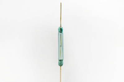
A reed switch is a switch with two magnetizable reeds in a glass tube that turns electrical contacts on and off.

When open, a typical reed switch opens with a small gap between the reed contact edges; when an external magnetic field (e.g., a magnet) is applied to the two reed contact edges, the reed contact edges attract each other and close, closing the circuit.

Uses of Reed Switches

Reed switches are used in the following applications:

Reed switches are turned on and off by magnets, so they can be used for non-contact detection. Reed switches are mainly used for non-contact detection of equipment status.

Principle of Reed Switches

The components of a reed switch include a glass tube, a reed strip, a magnet, and a contact.

  1. Two magnetic reed strips, which are easily magnetized, are enclosed in a glass tube with a certain overlap and spacing.
  2. When a magnet or other object is brought close, the contact edges associated with the two lead strips are attracted to each other, closing the circuit.
  3. When the magnet is moved away, the spring force of the leads opens the contacts.
  4. The contacts are sealed in a glass tube with nitrogen to insulate them from the external environment.

Since the contacts are not contaminated, reed switches have very low contact resistance. The contacts are mainly made of metal and have a short operating distance, giving them an open/close life of up to several hundred million cycles.

Other Information About Reed Switches

1. Failure of Reed Switches

Reed switches are components with moving parts. Therefore, there is no possibility of failure. The main possible failures include contact failure, contact sticking, and unexpected malfunction.

Contact Failure
Factors that can cause contact failure include deterioration of the magnet over time and carbonization due to chemical changes on the contact surfaces. Since carbonization of the contact surface is unlikely to occur in a nitrogen atmosphere, the glass capillary may be cracked.

Contact Sticking
Contacts may stick due to deterioration of the spring or welding of the contacts due to overcurrent. Deterioration of the spring is mainly due to aging, while welding of the contacts may be caused by an abnormality on the electric circuit side, so caution is required.

Unexpected Malfunction
Unexpected malfunctions may be caused by a random combination of the above two causes. In this case, it is very difficult to identify the cause.

Reed switches are components that are relatively unlikely to fail. To deal with failures, it is essential to design circuits with redundancy and prevent malfunctions. In addition, since reed switches are inexpensive, they are sometimes designed from the beginning on the assumption that they will be replaced at regular intervals.

2. Points to Note About Reed Switches

Reed switches sense the proximity of a magnet. However, because the operating range over which the switch operates is not uniform, there is a risk of chattering. Equipment design must take chattering into consideration.

On the other hand, the distance between the contacts of reed switches is very small and the contact pressure is very slight. Because they are precision components, they must be used strictly within their rated current values. In addition, even when used within the rated current value, care should be taken not to apply strong shocks.

In addition, using reed switches under a strong magnetic field may cause malfunctions. In such an environment, a magnetic shield should be provided to block external magnetic forces.

カテゴリー
category_usa

COM Express

What Is a COM Express?

COM Express

A COM Express (Computer On Module) is a COM standard defined by PICMG.

It refers to the adoption of technologies such as PCI Express and Serial ATA to existing COM. A COM Express board typically includes a CPU, memory, bus interface, and more, and it is connected to a carrier board and a card carriage. It is a device that can fully function as a computer.

The adoption of COM Express in products allows for speedy product development, simplified development, and reduced development costs. It also improves the future potential of the product, as modules compatible with the COM Express standard will be available in the market in the future.

Uses for COM Express

COM Express is used in a wide range of applications and industries due to its flexibility and scalability. Below are some key use cases:

1. Industrial Computers

In industrial applications such as factory automation, industrial control, and robotics, COM Express provides robustness and reliability in computer systems. Customizable features and expandability are essential to meet the specific requirements these applications.

2. Medical Equipment

For applications in the medical field, such as diagnostic and therapeutic equipment, COM Express offers reliability and high performance. Fast data processing and real-time responsiveness are critical elements in the diagnosis and treatment of patients.

3. Aviation and Defense Industry

COM Express modules are widely used in applications requiring high performance and reliability in the aviation and defense industry, such as aircraft navigation systems and military communications equipment. In these industries where robustness and long-term support are required, COM Express provides the ideal solution.

4. Telecommunication Networks

COM Express provides high-speed data transfer and high reliability to meet the requirements of telecommunication infrastructures. In devices such as network switches and routers, COM Express provides a reliable, high-performance platform.

Principle of COM Express

COM Express comprises a board with interfaces that can be connected to the CPU, memory, bus, USB, and other components. It also includes a card carriage insert and a connection to a carrier board. It can be mounted on a carrier board, and new modules can be inserted into the carrier board to expand the functionality of the product.

PCI Express, the technology used in COM Express, is a standard for expansion slots that can exchange electrical signals at high speed, allowing the insertion of graphics cards and other devices. Serial ATA, another technology used in COM Express, is a standard for connecting hard disks and other devices to COM Express, allowing them to exchange data at high speed.

Types of COM Express

COM Express offers a variety of form factors and pin assignments, depending on the application and requirements. The most typical of these are four form factors and three pin assignments.

1. Classification by Form Factor

  • COM Express Mini
    The smallest model, designed for applications requiring an extremely small footprint. It is typically found in mobile devices and small devices.
  • COM Express Compact
    Slightly larger than the COM Express Mini, this model offers more computing power and connectivity options. Its compact design makes it suitable for a wide variety of applications.
  • COM Express Basic
    The most common form factor, offering a wide range of I/O and high-performance computing options. They are widely used in industrial equipment, networking equipment, and other high-performance systems.
  • COM Express Extended
    The largest form factor, offering the most high-performance computing capability and the broadest range of I/O options. It is designed for the most demanding applications.

2. Classification by Pinout

  • Type 6
    The most common pinout, providing common I/O and display interfaces. It is typically used in applications where graphics processing power is critical.
  • Type 7
    Optimized for server applications and provides 10 Gigabit Ethernet (10GbE) and additional PCI Express (PCIe) lanes instead of a display interface.
  • Type 10
    This pinout is dedicated to COM Express Mini and prioritizes miniaturization and ruggedness. It is typically found in mobile and low power applications.

Thanks to these types, COM Express can adapt to a wide variety of requirements and applications and meet the needs of any industry. This is one of the reasons why COM Express is widely adopted in the industry.