カテゴリー
category_usa

Differential Probe

What Is a Differential Probe?

Differential Probes

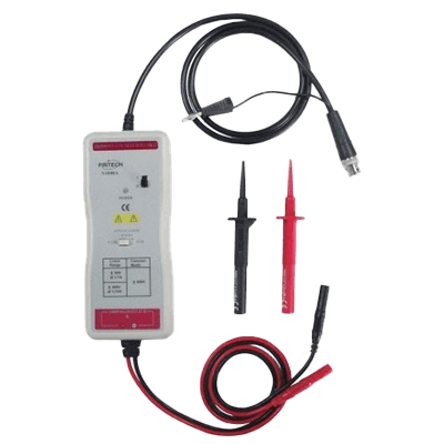
A differential probe is a device that, when measuring signals with an oscilloscope or similar device, detects noise generated from locations unrelated to the device transmitting the signal. This includes ground vibration, called common noise, and amplifies the measurement signal with an amplifier to make it easier to measure.

In communications such as USB and HDMI, it is necessary for the output side to detect signals accurately. If differential probes are used incorrectly, they can be broken or may not provide accurate output.

In many cases, differential probes are available from the same company that sells oscilloscopes, and since they have excellent connectivity, it is best to purchase a differential probe from the same company as the oscilloscope.

Uses of Differential Probes

Differential probes are used in the prototyping and testing phases of many communication devices, such as USB, HDMI, DisplayPort, Ethernet, and SATA, to detect noise with an oscilloscope and determine whether the noise is affecting the product or not. The differential probes are used to check for noise in USB, HDMI, DisplayPort, Ethernet, SATA, and other communications.

Differential probes are often expensive, so it is important to properly investigate whether they meet the standards for use before purchasing.

Principle of Differential Probes

A differential probe consists of two active probes that are identical in nature. One active probe is connected to the positive terminal of the connection of the device transmitting the signal to be measured, and the other to the negative terminal. By measuring the difference between the signals detected by these two probes, common noise can be detected.

Many differential probes are available on the market that have been devised to facilitate measurement of waveforms on an oscilloscope. For example, low-voltage signals can be amplified by an amplifier to make them easier to measure on an oscilloscope, some voltages can be grounded to avoid loading the oscilloscope with high-voltage signals, and signals can be made into clear square waves.

If the differential probe is properly selected according to the signal to be used, a clear noise measurement can be made.

Other Information on Differential Probes

1. Equivalent Circuit of a Differential Probe

A differential probe consists of two active probes, which are connected directly from the tip of the probe to the input end of a semiconductor circuit, so the input capacitance can be as small as 1pF, which is extremely small. On the other hand, unlike passive probes that use an attenuator, input resistance is in the tens of KΩ to 1MΩ range.

Therefore, when a differential probe is connected to a high-impedance circuit to measure waveforms, it is necessary to consider the measurement results in light of the influence of the probe. An effective way to do this is to connect the equivalent circuit of the differential probe to the circuit under test and simulate the effects.

In the case of a differential probe, between one pin and GND, the input resistance and input capacitance published by the manufacturer are connected in parallel. Similarly, the other pin and GND are connected in parallel with the input resistor and input capacitance. Thus, between the two pins of the differential probe, the input resistance is doubled and the input capacitance is halved. The effect of this impedance on the circuit under test should be taken into account when judging the measurement results.

2. Active Probe

Probes are used to measure stable signals. Without a probe, circuit operation would be affected by the capacitive component of the cable. This has a particularly strong effect on high frequency measurements.

Active probes use a semiconductor element at the input end. The input capacitance of the active probe itself is also very small, and some probes have input capacitances smaller than 1pF.

The input capacitance of the probe also affects the waveform. Passive probes have a larger capacitance component than active probes, and ringing, which is an oscillation of the waveform at the rising edge of the pulse, is significant.

3. High-Voltage Differential Probes

Differential probes are suitable for observing floating signal portions, but common probes have withstanding voltages of only 30 V to 100 V for both differential and ground voltages. Large high-voltage probes are required to measure floating points in circuits that handle high voltages, such as commercial power supplies. Probes with specifications of 6,000 V or more for differential voltage and 2,000 V or more for ground voltage are commercially available.

In measurements using high-voltage differential probes, the distance between the two pins must be sufficiently far apart to avoid the risk of discharge. As a result, ringing occurs in the high-frequency range due to the impedance of the lead wires, resulting in large amplitude fluctuations. As a countermeasure, twisting the two lead wires is effective.

4. Common Mode Noise

Noise in electric circuits can be broadly divided into differential mode noise and common mode noise. Differential-mode noise is noise conducted through conductors in a circuit.

Common mode noise, on the other hand, is noise that is partially conducted back through the earth or enclosure, and is noise in phase with the input signal and the signal on return. Common-mode noise is considered difficult to counter because of the complexity of how the noise propagates.

High-voltage differential probes are a very effective means of testing the operation of switching power supplies. Switching regulators generate common-mode noise with ground voltage fluctuations of several hundred volts.

Although a differential probe should cancel the ground voltage fluctuations and allow observation, it is inevitable that a small amount of the ground voltage fluctuation will actually be added to the differential output. To reduce the effect of this variation, it is necessary to select a probe with excellent CMRR (Common-Mode Rejection Ratio).

カテゴリー
category_usa

Hydraulic Cylinder

What Is a Hydraulic Cylinder?

Hydraulic Cylinders

A hydraulic cylinder is an actuator that converts energy into mechanical motion. By controlling the amount of oil inside, the pressure is changed to control the motion of the piston.

Hydraulic cylinders come in single-acting and double-acting types, which differ in the number, position of valves, and internal geometry.

Hydraulic cylinder is used in various applications such as car brakes, elevators, and construction machinery because of their low noise and high output.

Uses of Hydraulic Cylinders

Hydraulic cylinders are used in many products because they can transform a small force into a large force. The most typical product used is a car brake system, where the small force of a foot push can generate a large force to stop the car. They are also used in elevators, construction equipment, and many other occasions where strong force is required, indicating their wide range of use. When making a selection, the pressure to be used, size, stroke width, and cycle should be taken into consideration.

Principle of Hydraulic Cylinders

Hydraulic cylinders contain a piston, and the piston is moved by injecting oil into the cylinder through a valve or by suctioning oil from the cylinder. The principle of operation of hydraulic cylinders varies depending on the position, number, and type of valves.

Single-acting hydraulic cylinders have one valve while double-acting hydraulic cylinders have two valves, which control piston movement by changing the pressure in the cylinder by changing the amount of operating oil. The piston is pushed out by reducing the oil in the valve on the bottom side to reduce the pressure or by increasing the oil in the valve on the opposite side to increase the pressure. When pulling the piston, the increase or decrease of the operating oil is reversed. In single-acting hydraulic cylinders, the piston is returned by its weight or a spring.

Types of Hydraulic Cylinders

As mentioned above, there are two types of hydraulic cylinders: single-acting and double-acting. Single-acting types are classified into ram type, piston type, double-rod type, and single-acting telescopic type. Double-acting types include piston, double-rod, double-cylinder, and telescopic types.

When selecting hydraulic cylinders, first clarify the required thrust and supply pressure and then determine the appropriate pressure receiving area. Increasing the pressure-receiving area of the cylinder or the pressure to be supplied will increase the output. In addition, what is used depends on the value of “nominal pressure,” which is the maximum value set pressure of the hydraulic cylinders. Typical examples include those for 7 MPa and 14 MPa. The most commonly used cylinder material is iron, but if a magnetic switch for stroke detection is installed, a stainless steel cylinder is used.

How to Use Hydraulic Cylinders

Hydraulic fluids used in hydraulic cylinders include petroleum-based, synthetic, and water-molded hydraulic fluids. Any of these hydraulic oils can be used, but it is advisable to check the specifications of each hydraulic cylinder when selecting one. It is recommended that the oil be filtered because the foreign matter in the hydraulic oil can interfere with regular operation.

To adjust the speed of the hydraulic cylinders, install a flow control valve in the hydraulic circuit to control the oil flow in the cylinder. In general, the amount of oil entering the cylinder is adjusted.

Also, when the hydraulic cylinders are operated, the air in the syringe must be purged. If the cylinder is pressurized with air in it, adiabatic compression will cause the air to become hot, which may cause seals to burn out.

カテゴリー
category_usa

Non-Contact Temperature Sensor

What Is a Non-Contact Temperature Sensor?

Non Contact Temperature Sensors
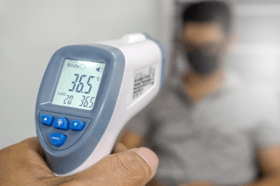
A non-contact temperature sensor is a sensor that can detect temperature without being directly attached to the object being measured.

They use infrared rays emitted by an object or scattered by incident neutrons. Most non-contact temperature sensors on the market are infrared sensors. Infrared rays are detected using a sensing element, and the emissivity is used to calculate the temperature of the object being measured. Emissivity is the amount of infrared radiation relative to the surface temperature determined for each object, and is necessary when using non-contact temperature sensors.

Non-contact sensors have a specific range or distance over which they can measure, and the range over which they can measure is called the spot diameter. The smaller the spot diameter is compared to the object or person being measured, the more stable the temperature can be measured. In addition, when measuring high-temperature objects, it is necessary to take measures such as cooling the non-contact temperature sensor to prevent it from being damaged due to the heat generated by the sensor itself.

Uses of Non-Contact Temperature Sensors

Non-contact temperature sensors are used in a wide range of applications, from everyday life to industrial use. The following are examples of non-contact temperature sensor applications.

  • Measuring the temperature of food during the baking process in food factories
  • Temperature measurement to determine the degree of drying of industrial products after painting
  • Measurement of product temperature distribution during lathing
  • Measurement of body temperature

Non-contact temperature sensors are used in situations where it is difficult or impossible to measure with contact-type temperature sensors. Specifically, they are used for moving or rotating objects.

It is also used to measure body temperature. They are used in numerous situations, such as in restaurants and when going to work in an office. Compared to contact thermometers that are inserted under the arm, the advantages of these thermometers are that they measure temperature faster and are more hygienic, eliminating the need to disinfect them after each use.

On the other hand, because they use infrared rays, they are greatly affected by external factors such as ambient temperature and sunlight. In addition, they are less accurate than contact sensors. It is necessary to adjust the temperature calculation method and improve the environment while taking into consideration the location where the non-contact temperature sensor will actually be utilized.

Principle of Non-Contact Temperature Sensors

A non-contact temperature sensor using infrared rays consists of a light-collecting lens, thermopile, amplifying amplifier, and arithmetic unit. Temperature is measured in the following sequence

1. Infrared Light Collection

Infrared light is invisible from 0.7 to 1,000 μm. Within this frequency range, only frequencies between 0.7 μm and 20 μm are used for practical temperature measurements.

This light is focused using an infrared condenser lens. By focusing infrared rays in the wavelength range detectable by the thermopile, measurement accuracy can be improved.

2. Conversion to Electrical Signals

Thermopiles are used to convert infrared rays into electrical signals for output. The thermopile is an infrared detection element that outputs an electrical signal in response to the temperature heated by infrared rays.

Within the thermopile, multiple thermocouples are connected in series with the warm junction facing the center, and an infrared absorbing film is placed at the center where the warm junction faces. Light collected by the lens hits only the warm junction, creating a temperature difference between the warm junction and the cold junction on the outside. This creates a voltage difference due to the Seebeck effect, enabling temperature measurement.

3. Amplification of Electrical Signals

An amplifying amplifier is used to amplify the electrical signal emitted from the thermopile. Amplification enables detection with higher accuracy.

4. Calculating Temperature From Emissivity

Corrections are made to calculate the temperature of the object to be measured. Emissivity is used for the correction. Emissivity is the ratio of the amount of infrared radiation emitted to the surface temperature of an object, which is a constant value for each object.

The temperature of the object to be measured is calculated using the amount of infrared radiation detected from the electrical signal converted by the thermopile and the emissivity of the object to be measured, which is measured in advance.

Types of Non-Contact Temperature Sensors

Non-contact temperature sensors can be classified into portable and installed types.

1. Portable Type

Portable sensors are held by a person and used to measure temperatures. Since it does not require a power supply, it can be easily carried around. They are lightweight, compact, and often inexpensive, ranging from several thousand yen to several tens of thousands of yen.

2. Installation Type

The target object passes in front of the device, and the temperature can be measured automatically without human intervention. Many of these products combine a thermographic camera and other equipment, and are often expensive, ranging from several hundred thousand yen to several million yen. The measurement does not require the user to touch the device, and depending on the device, measurements can be taken from a distance of 0.5 to 1.5 meters.

カテゴリー
category_usa

Heat Exchanger

What Is a Heat Exchanger?

Heat Exchangers
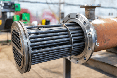
A heat exchanger is a device that transfers heat between fluids, such as air and water.

A typical device that uses a heat exchanger is an air conditioner, a machine that regulates room temperature by a heat exchanger between a refrigerant and air. Various structures have been developed, and appropriate selection is necessary according to the fluid used for heat exchange.

Uses of Heat Exchangers

Heat exchangers are used in a variety of applications, from household appliances to industrial applications.

The following are examples of heat exchanger applications:

  • Air conditioning equipment, such as home air conditioners and water heaters
  • Radiators in cars
  • Commercial refrigerators in frozen food plants
  • Gas temperature control in process plants
  • Steam turbine condensers and coal economizers
  • CPU cooling in computers

In the home, heat exchangers are used in air conditioners and refrigerators. They maintain the required temperature by transferring heat from the room or inside the cabinet. Heat exchangers are also used in water heaters and floor heating systems.

There are countless examples in industry. Factories with industrial furnaces use industrial water or seawater to cool their jackets in heat exchangers. Heat exchangers are also widely used in infrastructure facilities such as power plants, and condensers in steam power generation are also a type of heat exchanger.

Heat exchangers such as heat sinks are used to cool computers. This is a product with many heat sinks, which are installed directly on the heat-generating medium and use the ambient air as a cooling medium.

Principle of Heat Exchangers

A heat exchanger consists of piping and fins.

Piping is the structure through which the medium to be heated or cooled flows. Generally, they are made of metal, and a variety of products are available, such as stainless steel and copper, depending on the application. When a fluid that serves as a heat source flows through it, it is called a heat medium pipe, and when a fluid that serves as a cooling source flows through it, it is called a refrigerant pipe.

A fin is a structure that efficiently dissipates heat. Aluminum is often used because of its excellent heat transfer characteristics. They are attached to the piping in the form of pleats.

Depending on the direction of flow of low-temperature fluid and high-temperature fluid, there are two types: countercurrent and parallel flow. When they flow in opposite directions, they are of the countercurrent type, and when they flow in the same direction, they are of the parallel flow type. Generally speaking, the directional flow type is more efficient for heat exchange.

Types of Heat Exchangers

Typical types of heat exchanger structures include multi-tube heat exchangers, plate heat exchangers, and spiral heat exchangers. Other types include air-fin type, fin-tube type, and coil type.

1. Multi-Tube Heat Exchanger

A multi-tube heat exchanger consists of a thick circular tube and many thin circular tubes inside the circular ring. The fluid to be exchanged flows into the thick tube, and the refrigerant or cooling water flows into the thin tube. Since each pipe is partitioned, the fluids do not mix and heat is exchanged between them.

2. Plate Type Heat Exchanger

This heat exchanger consists of a number of specially processed metal heat transfer plates that are stacked on top of each other, and the high-temperature fluid and low-temperature fluid flow alternately across the plates.

This heat exchanger easily achieves a turbulent flow effect and a high heat exchange rate. They also have the advantage of a compact design and are less likely to cause problems in terms of installation location. Because of the stacked structure of the heat transfer plates, the number of plates can be changed according to the process requirements. However, it is difficult to use this type of heat exchanger with fluids that have high viscosity or contain particles, as these fluids can cause blockage between the plates.

3. Spiral Type Heat Exchanger

A spiral heat exchanger is a heat exchanger that exchanges heat between two fluids in a spiral-shaped flow path where the two fluids do not mix.

The inside of the channel is a single flow path, and even if a substance adheres to the walls of the heat exchanger, it can be peeled off from the walls. This is because the channel width is shortened and the flow velocity is increased. Therefore, it is suitable for the heat exchange of fluids containing impurities.

4. Air-Fin Heat Exchanger

This heat exchanger consists of a tube and a fan. It is used for cooling. The fluid to be cooled flows through the tube and is cooled by air flowing through it using the power of the fan.

5. Finned Tube Heat Exchanger

This type of heat exchanger has fins (heat-transfer plates) installed on tubular tubes to increase the heat-transfer area. This type of heat exchanger is used in air conditioner heat exchangers.

6. Coil Type Heat Exchanger

This is a heat exchanger in which the heat transfer tubes are coiled and the outside is surrounded by a cylinder or the like. A cooling or heating medium is inserted into the tube to exchange heat with the tube side.

カテゴリー
category_usa

Gasket

What Is a Gasket?

Gaskets
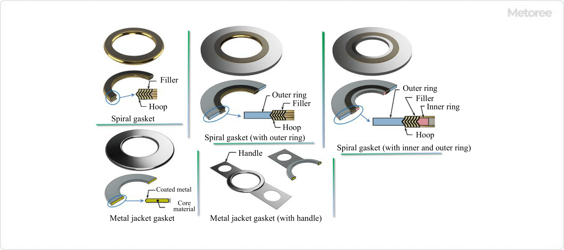
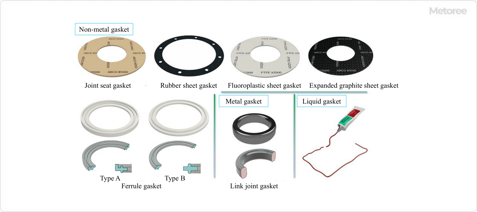
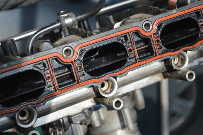
A gasket is a part or material used in equipment, structures, piping, etc. to maintain airtightness and sealing to prevent internal fluids from leaking out.

In general, there are two types of gaskets and packings for sealing purposes. Gaskets are mainly used for “motionless” or “non-moving” parts. Gaskets are mainly used for “motionless” or “non-moving” parts, while packing is mainly used for “moving” or “movable” parts.

Uses of Gaskets

336_Gaskets_ガスケット-1.png

Figure 1. Example of gasket use (1)

Gaskets are used to fill and seal gaps in flat areas such as pipe flanges, machine joints, and covers. The main reason is to prevent leakage of internal fluids by maintaining and sealing tightness, but they are also used to prevent foreign matter from entering through gaps in joint surfaces.

336_Gaskets_ガスケット-2.png

Figure 2. Example of gasket use (2)

Generally, gaskets are inserted between joint surfaces and tightened with screws or bolts to enhance sealing by the surface pressure.

Principle of Gaskets

Gaskets are inserted between joints of piping flanges or machine parts, tightened by screws or bolts, compressed to a certain thickness and shape, and sealed by the surface pressure. Therefore, the proper tightening method and tightening force of gaskets vary depending on the material, thickness, shape, structure and material.

In particular, for gaskets for pipe flanges and pressure vessel flanges, the following standards specify the tightening method and control method. It is necessary to refer to these standards and each manufacturer’s proper tightening surface pressure for optimum tightening management.

  • Japanese Industrial Standard JIS B2251:2008 Tightening method for flange joints
  • Japanese Industrial Standard JIS B8265:2010 Structure of Pressure Vessels General Items
  • Japan Petroleum Institute Standard JPI-8R-15-2008 Tightening control of flanges and bolts
  • ASME ASME PCC-1-2013 Guidelines for Pressure Boundary Bolted Flange Joint Assembly

In general, when used for flanges, the tightening force required to seal the fluid is the bolt load (tightening force) in service (Wm1) and the bolt load (tightening force) when tightening the gasket (Wm2), as specified in JIS B8625.

Liquid gaskets are applied to the joint surface and tightened to form a uniform, hardened, adhesive thin film that provides a tight seal.

Types of Gaskets

There are various types of gaskets, depending on the material, shape, and structure. See the table below for the main types.

336_Gaskets_ガスケット-3.png

Figure 3. Types of gaskets

1. Non-metallic Gasket

Joint Sheet Gasket
Joint sheet gaskets are gaskets made by adding rubber and fillers to glass fiber material, rolling, and vulcanizing to form a sheet. The sheet material is punched or cut to the size and shape of the joint surface of piping flanges and machine parts. They are used in a wide variety of situations, with a high degree of dimensional flexibility, and are used in a wide range of applications, from high and low temperatures to high and low pressures, and are also highly versatile with excellent oil and heat resistance.

Rubber and Synthetic Rubber Sheet Gaskets
Rubber and synthetic rubber sheet gaskets are sheet gaskets made of natural rubber, nitrile rubber, silicon rubber, and other materials. They are punched or cut to the required size and shape. They are used for relatively low-pressure and low-temperature fluids.

Fluoroplastic PTFE Sheet Gasket
This gasket is a sheet of fluoroplastic PTFE compression-molded gasket. Inorganic fillers and carbon-based fillers are added to improve heat resistance, chemical resistance, acid resistance, and alkali resistance. They are used for highly corrosive chemicals, food piping flanges, and equipment.

Expanded Graphite Gasket
These gaskets are made of graphite that has been treated with chemicals, heated to a high temperature for expansion, and formed into a sheet shape. They are punched or cut to the required size and shape. Since the sheet by itself has low strength, some are reinforced by sandwiching or laminating a thin stainless steel plate between them to increase strength.

It has excellent heat and chemical resistance, and is used for flanges and equipment in general-purpose piping. They are also used for flanges of piping for highly permeable fluids, cryogenic LNG and liquid nitrogen.

Ferrule Gasket
The Herule gasket is a standard gasket that conforms to the Herule flange for sanitary piping. Materials include ethylene-propylene rubber (EPDM), fluoroplastic (PTFE), and silicone rubber. These gaskets are used in flanges for food, pharmaceutical and chemical piping, and equipment.

2. Semi-metallic Gasket

336_Gaskets_ガスケット-4.png

Figure 4. Semi-metallic gasket

Spiral Gasket
A spiral gasket is a gasket consisting of a hoop of thin iron or stainless steel sheet formed into a V-shaped cross section and a buffer material of the same shape, such as expanded graphite, fluoroplastic PTFE, or non-asbestos paper, alternately wrapped around the hoop.

The state consisting of hoop and filler is the basic form. In addition to the basic type, there are gaskets with an outer ring for proper positioning of the flange joint surface and with an inner ring to reduce deformation due to tightening force. These gaskets are used for flanges for fluid piping such as high-temperature, high-pressure steam and heat-transfer oil.

Metal Jacket Gasket
Metal jacket gaskets are gaskets consisting of a highly heat-resistant core material (cushioning material) wrapped around a thin coated metal plate of carbon steel, stainless steel, copper, or Monel (nickel-copper alloy). They are used for high-temperature, high-pressure, acid- and alkali-resistant piping flanges and equipment joints such as heat exchangers and pressure vessels.

336_Gaskets_ガスケット-5.png

Figure 5. Non-metallic gasket, metallic gasket, and liquid gasket

3. Metal Gasket

Metal Gasket
Metal gaskets include “metal corrugated gaskets,” which are thin mild steel or stainless steel sheets bent into a corrugated cross section and processed into a ring shape; “metal flat gaskets,” which are single sheet rings of mild steel or stainless steel sheets; and “saw-tooth gaskets,” which are circular V-shaped grooves processed on the back surface of a flat shape. These gaskets are used for cylinder block and cylinder head joint surfaces of engines and flanges for high-temperature, high-pressure piping.

Ring Joint Gasket
Ring joint gaskets are made by machining forged metal into a ring shape and fitting it into a ring groove on the flange joint surface. The cross section of the ring can be oval, octagonal, hexagonal diamond, triangular delta, or round.

Materials include mild steel, stainless steel, Monel (nickel-copper alloy), titanium and aluminum. They are used in equipment joints such as flanges for high-temperature, high-pressure steam, gas, and oil piping, and pressure vessels.

4. Liquid Gasket

Liquid gaskets are used in a variety of situations, such as PVC pipes for rainwater drainage and engine joints. They are low-cost because they are effective even when applied in small quantities, and because they blend well with the joint surface, they provide good sealing even at low tightening surface pressure and relatively low machining accuracy, and they require no retightening, which makes them highly efficient in operation.

There are several types, including organic solvent (modified alkyd-based, fiber ester-based, synthetic rubber-based), solvent-free (phenolic-based, modified ester-based, silicone-based, acrylic-based), and water-based types (water-based acrylic-based).

カテゴリー
category_usa

Ferrite Magnet

What Is a Ferrite Magnet?

Ferrite Magnets

Ferrite magnets are made by mixing iron oxide with cobalt, nickel, and manganese. The molecular formula is represented as MFe2O4 (M = Mn, Fe, Co, Ni, Cu, Mg, Zn, Cd, etc.).

The composite metal M is dominated by divalent cations, and Fe3O4, where M = Fe, is black and is a well-known raw material called magnetite. Other compounds exist where the compound metal M is 1, 3, or even tetravalent cations, called ferrite.

The manufacturing process involves pressing powdered ferrite and baking it at high temperatures. It is also a type of ceramic. It can be synthesized from iron oxide Fe2O4 and is therefore inexpensive.

The characteristics of ferrite magnets are that they can be easily formed into any shape and are easy to process and that they are chemically stable and resistant to corrosion by rust and chemicals.

Applications of Ferrite Magnets

Applications of ferrite magnets can be divided into two types: hard ferrite and soft ferrite.

1. Hard Ferrite

Hard ferrite magnets are ferrite magnets that become permanent magnets once they are attached to a strong magnet (by applying a strong magnetic field). U-shaped magnets are the most common type of magnet we see in our daily lives.

U-shaped magnets are typical examples. They are also used in small motors, speakers, headphones, and cassette tapes. 

2. Soft Ferrite

Soft ferrite is a ferrite magnet that becomes a magnet when in contact with a magnetic field and ceases to be a magnet when removed from the field. It is often used as a magnetic core and is suitable for transformers and coils.

Examples of easy-to-understand applications are used in radios, televisions, game consoles, automobiles, personal computers, microwave ovens, vacuum cleaners, and refrigerators.

Principle of Ferrite Magnets

The magnetic properties of ferrite magnets differ between hard ferrites and soft ferrites. First, let us explain the magnetic properties. Figure 1 shows the spin state of each magnetic property.

1. Magnetic Properties

  • Ferromagnetic: A material whose magnetic moment (a vector quantity that expresses the strength and direction of a magnet) is aligned without the application of a magnetic field is called a ferromagnetic material.
  • Ferrimagnet: A ferrimagnetic material is one in which the magnetic moments of neighboring atoms are opposite in direction but different in magnitude so that the material as a whole is magnetized. All ferrite magnets are ferrimagnetic.
  • Paramagnetic: When there is no magnetic field, the magnetic moments are oriented in various directions, but when a magnetic field is applied, the magnetic moments become aligned.

The types and characteristics of each type of ferrite magnet are shown in Figure 2. Saturation magnetization is the maximum magnetization at which the magnetization of a material does not increase even if the magnetic field is increased. Curie temperature is the temperature at which the magnet changes from ferromagnetic to paramagnetic.

2. Hard Ferrite

Hard ferrite is a ferromagnetic material and a permanent magnet. Hard ferrites can be further classified into isotropic and anisotropic magnets according to the orientation of the magnetic poles of their molecules.

  • Isotropic Magnets: The magnetic moment is oriented in various directions. Since the orientation of the magnetism is not uniform, it can be magnetized from any direction, but the magnetic force is weak.
  • Anisotropic Magnets: The orientation of the magnetic moment of the molecules is aligned, providing directionality but a strong magnetic force. It is produced by aligning the magnetic poles of each ferrite molecule by applying a magnetic field during the hardening process.

3. Soft Ferrite

Soft ferrite is magnetic only while an external magnetic field is applied. Although the magnetic field is smaller than that of hard ferrite, it has excellent magnetic properties over a wide frequency range.

For example, a spinel-type crystal structure has a high magnetic permeability (the degree to which a material is magnetized) over a wide range of frequencies. The garnet type has the property that single crystals are not easily broken in the microwave frequency range.

Comparison With Alnico Magnets

Alnico magnets are manufactured by adding aluminum (Al), nickel (Ni), cobalt (Co), and other additive elements to iron and using casting methods or powder sintering.

Alnico magnets are characterized by their extremely high Curie temperature (the temperature at which they cease to be permanent magnets) of 860°C, allowing them to be used in high-temperature environments. Alnico magnets can recover their original magnetic force when returned to room temperature at temperatures ranging from room temperature to 400℃. Those manufactured by casting also have excellent mechanical strength.

Applications for Alnico magnets include electric motors, sensors, speaker units, and magnetic pickups for electric guitars.

Differences From Ferrite Magnets

Ferrite magnets are primarily composed of iron oxide, while Alnico magnets are composed primarily of iron with aluminum, nickel, and cobalt added. The retention of magnetic force in an Alnico magnet is small and easily demagnetized.

There is a limitation that they must have a long shape due to the need for a long distance between the poles. Also, the supply of the raw material, cobalt, is unstable and expensive, so ferrite magnets are less expensive.

Comparison With Samarium Cobalt Magnets

Samarium cobalt magnets are rare earth magnets composed of samarium (Sm) and cobalt (Co). They are divided into SmCo5 (1-5 series) and Sm2Co17 (2-17 series) according to their composition ratio, with the 1-5 series, which contains less samarium, being widely used today.

Samarium cobalt magnets are characterized by a high Curie temperature of approximately 800°C at maximum. Because of its excellent corrosion resistance, it can be used as is without surface treatment, and its shape is highly selectable. Magnetic properties are higher than those of ferrite magnets and second only to those of neodymium magnets.

Differences From Ferrite Magnets

Because they can be used in environments up to about 350°C, they are used in space-saving, high-temperature environments where higher magnetic force than ferrite magnets is required. On the other hand, it has the disadvantage of low strength, which makes it prone to cracking and chipping. The raw materials samarium and cobalt are both rare, making them very expensive compared to ferrite magnets.

Comparison With Neodymium Magnets

A neodymium magnet is a magnet composed mainly of neodymium (Nd), iron (Fe), and boron (B). Neodymium magnets are characterized by their easy oxidation and high thermal dependence.

Because they oxidize easily, their surfaces are nickel-plated before use. They are usually used at temperatures below 80°C. Because of its relatively high strength, it is also resistant to cracking and chipping.

Differences From Ferrite Magnets

Compared to ferrite magnets, magnetic properties are extremely high, with about four times the magnetic holding power and 10 times the maximum energy product. It is more expensive than ferrite magnets, but less expensive than samarium cobalt magnets.

カテゴリー
category_usa

Compressor

What Is a Compressor?

Compressors
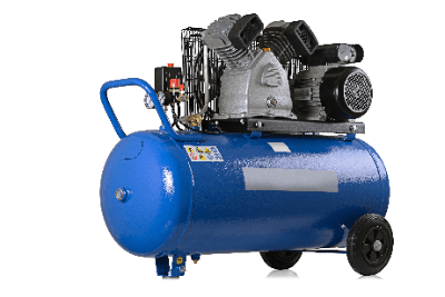
A compressor is a machine that compresses and pumps gas through the rotary motion of a rotor or the reciprocating motion of a piston.

Typical compressed gases include air, hydrogen, and refrigerants. Several methods have been developed to compress air, and selection is based on compression pressure, flow rate, and other factors. When the compression pressure is ultra-high, the risk is extremely high, so it is important to pay close attention to safety.

Uses of Compressors

Compressors are used in a wide range of applications, from home appliances to industrial equipment.

The following are examples of applications:

When air is stored in compressors during times when electricity is low and used during times when it is high, it contributes to electricity cost savings.

Principle of Compressors

Compressors can be broadly classified into “turbo type” and “positive displacement type.”

1. Turbo Type Compressor

The turbo type compresses air by giving it kinetic energy. It is further divided into centrifugal and axial flow types.

  • Centrifugal Compressors
    Centrifugal compressors use an impeller to compress gas in a centrifugal direction. While this type is suitable for larger sizes, it is not suitable for high compression.
  • Axial Compressor
    Axial-flow compressors use rotating blades to compress air flowing in an axial direction. It can handle high compression by stepwise compression and is also suitable for larger sizes. They are also used in jet engines

2. Positive Displacement Compressor

The positive displacement type compressor compresses by volume change and is further divided into reciprocating and rotary types.

  • Reciprocating Compressors
    Reciprocating compressors use the reciprocating motion of a piston to compress gas. When the compressed gas becomes higher than the internal pressure of the tank, the check valve opens and the gas is transported to the tank for compression.
  • Rotary Compressor
    In the rotary type, the piston motion of the reciprocating type is replaced by a rotary motion such as a screw. Compared to the reciprocating type, the rotary compressor is characterized by its low noise level.

Other Information on Compressors

1. How to Use a Compressor

Compressors are often used to compress air. In addition, automatic tools are sometimes driven by compressed air from air compressors at construction sites. These automatic tools are called air tools. Depending on the air tool installed, multiple tasks can be automated with air.

Generally, modern compressors automatically control the pressure, but the procedure is as follows:

  • Install the air tool before turning on the compressor.
  • Power is turned on. If there is no compressed air, the compressor starts up and begins making compressed air.
  • When the pressure in the tank rises to the specified pressure, the compressor automatically stops or runs without load.
  • The air tool is used to perform various tasks.
  • When a certain amount of air is consumed, the tank pressure drops and the compressor restarts or runs again under load. 

2. Compressor Oil

A compressor is a piece of equipment that compresses and pumps air or process gas. Compressor oil (lubricating oil) is used to prevent wear and leakage of gases due to contact with the metal piston and screw. Oil should be selected according to the type of compressor.

The oil used in power machinery is specified by the international standard of viscosity ISO VG, according to the application, and the greater or lesser of this value indicates the degree of viscosity. Compressor oil for reciprocating compressors has a viscosity of about VG68, which is slightly high viscosity.

On the other hand, screw type compressors use low viscosity oil to reduce the load on the rotor. There are two main types of oil: mineral oil and synthetic oil. Synthetic oil is used in many compressors because it is less prone to deterioration than mineral oil. Compressor oil must also have excellent resistance to high temperature loading during compression, high-temperature oxidation, and sludge derived from fine particles in the air.

カテゴリー
category_usa

Pulse Generator

What Is a Pulse Generator?

Pulse GeneratorsA pulse generator is a device that generates rapidly occurring and converging electrical signals called pulses.

Pulse generators can adjust pulse frequency, pulse width, voltage level, and timing delay. Pulse generators include pulse delay generators, burst generators, and gate generators.

Uses of Pulse Generators

Pulse generators are used in a wide range of applications, from industrial to consumer products.

Familiar products include medical pacemakers and automobile engines. These applications take advantage of the pulse generator’s ability to input pulses of electrical signals at high speed.
Other applications include strobe control and observation of high-speed moving objects.

Another common use is as a power source for semiconductor lasers (LDs). A semiconductor laser emits light when electricity exceeding a threshold value is input. A pulse generator is necessary when the laser light is pulsed. Pulsed lasers are mainly used for laser processing and signal transmission.

Principle of a Pulse Generators

To generate pulses with a pulse generator, a commercial alternating current must be converted to a direct current by a transistor or other means. In addition, the DC current is converted to a higher voltage by means of a capacitor or other storage device.

The most common method for generating pulse current from high-voltage current is to use a concentrated constant circuit. In a concentrated constant circuit, a gap switch is used. The gap switch allows the charge to accumulate in the capacitor until a threshold value is reached and then releases the charge when the threshold value is reached. The repetition of this process generates a pulse.

Types of Pulse Generators

There are several types of pulse generators depending on their application and function. Therefore, it is necessary to select the appropriate one for each application. The three main types of pulse generators used are pulse delay generators, burst generators, and gate generators.

1. Pulse Delay Generator

A time delay can be applied to the pulse oscillation. Also, the timing of the light-receiving device can be matched to the laser oscillation.

2. Burst Generator

The burst trigger is used as the criterion for judging whether the gate is valid or invalid. Therefore, regardless of whether the reference signal is input or not, no pulse is output unless the burst trigger is input to the generator. It is often used for the evaluation of wireless terminals.

3. Gate Generator

A pulse generator whose output pulses can be controlled by a gate trigger. Pulses are output when a reference signal is input during the gate trigger input. In the case of burst triggering, the gate generator will accept all subsequent reference signals that are input once, but will not accept a reference signal if the gate trigger is disabled.

Other Information on Pulse Generators

Price of Pulse Generators

Pulse generators are expensive and are a fixed asset when purchased. Besides, their use is often temporary, unless they are built internally for processing machines.

Therefore, they are often procured through rental or lease.
Prices range widely from 300 to 6000 USD (monthly) depending on performance. Some high-performance pulse generators made by major U.K. manufacturers can cost 7500 to
40,000 USD when purchased.

カテゴリー
category_usa

Controller

What Is a Controller?

A controller is a device used to adjust a machine’s output automatically.

Often sold under indicating regulators or temperature regulators, many devices marketed as controllers can also control parameters other than temperature.

Physical parameters such as temperature, humidity, pressure, and flow rate are input from sensors to indicate a value. Feedback is applied to match this with the target value you set. Most products have a display for monitoring both the current value of the parameter being adjusted and the set value.

If the display uses an analog pointer, it is termed an analog controller. If it features a 7-segment display, it is called a digital controller. Currently, digital controllers are the most common type. In analog controllers, the display may omit the current value.

Uses of Controllers

Controllers are widely used in applications ranging from industrial equipment to household appliances, as exemplified below:

Controllers are utilized to maintain constant parameters and may be used alongside computers to log monitored data.

Principle of Controllers

A controller consists of a sensor, a processing/monitoring part, and an output section. The sensor inputs physical quantities such as temperature (using a thermometer) or humidity (using a hygrometer), among others.

The processing and monitoring section adjusts the output while monitoring the value. A built-in comparator or similar device compares the measured value to the target value to determine the output, which is then sent to the output section. Various feedback control methods are employed.

1. ON/OFF Operation

Output is activated when the measured value is below the target value and turned off when above. This repeated operation maintains the measured value near the target.

2. Proportional Operation (P Operation)

This operation adjusts the control output proportionally to the deviation from the target value, enabling smoother regulation than ON/OFF operation, though with relatively large fluctuations near the target. Integral operations, etc., adjust the stabilization offset slightly off the target value.

3. Integral Operation (I Operation)

Based on the time integral of the difference between the target and measured values, this operation is often used to eliminate offset appearing in proportional operation, typically in conjunction with P operation.

4. Differential Operation (D Operation)

This operation outputs based on the rate of change (derivative) of the measured value. PID operation, combining P, I, and D operations, integrates the benefits of each method.

How to Select a Controller

Controllers are selected based on mounting size, input specifications, output specifications, communication methods, and other factors.

1. Mounting Size

Consider the panel size where the controller will be mounted. Select a product that fits the available installation space, opting for smaller sizes if mounting multiple controllers in a row.

2. Input Specifications

Choose based on the controlled physical quantity’s input signals and number of input points. For temperature inputs, resistance thermometers or thermocouples (PT100Ω, K, R, B types) are common, with 4-20 mA or 1-5 V inputs for other parameters.

3. Output Specifications

Output specifications match the signal transmitted to the output device. Analog control typically uses 4-20 mA or 1-5 V outputs, while ON-OFF control employs contact or transistor outputs, selected based on the output device’s specifications.

4. Communication Method

For interfacing with computers, communication methods facilitate transmitting measured or output values to a computer or altering target values from a computer. Ethernet communication has become mainstream, succeeding older serial communication standards like RS422 or RS485.

Insulation Tester

What Is an Insulation Tester?

Insulation Resistance Testers

An insulation tester is a device used to diagnose insulation conditions. Insulation resistance testers capable of applying high voltages of about 1,000 VDC according to the system voltage are also available.

It is essential for any equipment that uses electricity to be well insulated. If the insulation deteriorates, it can cause electrical leakage, fire, or electric shock. To prevent the above accidents from occurring, it is necessary to evaluate the insulation performance periodically with an insulation resistance tester.

Usage of Insulation Testers

Insulation testers are used to quantify insulation capability. It is rarely seen in ordinary households.

In production, they are used for the final testing of electrical products at the factory where they are shipped. In addition, maintenance personnel of electrical equipment often have it as a measuring instrument for maintenance.

Resistance measurement involves the application of a voltage, and the applied voltage varies according to the system voltage.

Insulation Tester Principle

Insulation testers include wiring terminals, switches, DC power supplies, ammeters, and current protection elements.

The wiring terminal uses two terminals: the ground terminal and the line terminal. The ground terminal is grounded, and the line terminal is connected to the measuring section for measurement.

By pressing the switch, a DC voltage created by a DC power supply is applied. The minute current flowing to the earth is called leakage current, and the insulation resistance is obtained by measuring the leakage current when the voltage is used with an ammeter.

Since a high-voltage is applied, the impedance is increased with a current protection element to prevent overcurrents from flowing in the circuit. Due to the existing protection element, the internal impedance of the insulation resistance tester is designed to be very high.

The insulation performance is better with a higher the insulation resistance value. The insulation resistance value will be extremely low if an insulation breakdown occurs.

Other Information on Insulation Testers

Insulation resistance testers measure the insulation condition of electric lines and electrical components installed in factories and homes.

Causes of insulation defects may include poor installation of electrical circuits, poor insulation between charging and non-charging parts, deterioration over time, deterioration of internal wiring, damage due to shorts in parts used, and damage to the housing. If left unattended, these problems can lead to extremely dangerous electrical leakage, fires, and electrocution.

To prevent such problems, shut off the power supply system and measure insulation resistance as soon as the leakage breaker trips or an electric shock occur during operation appears.